Experimental Approach for Metals Mechanical Behavior Characterization at High Temperature: Development of a Complex Tensile Test Machine †


 and
and 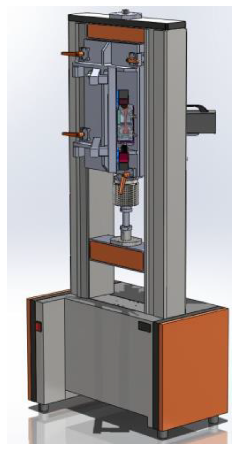
Abstract
:1. Introduction
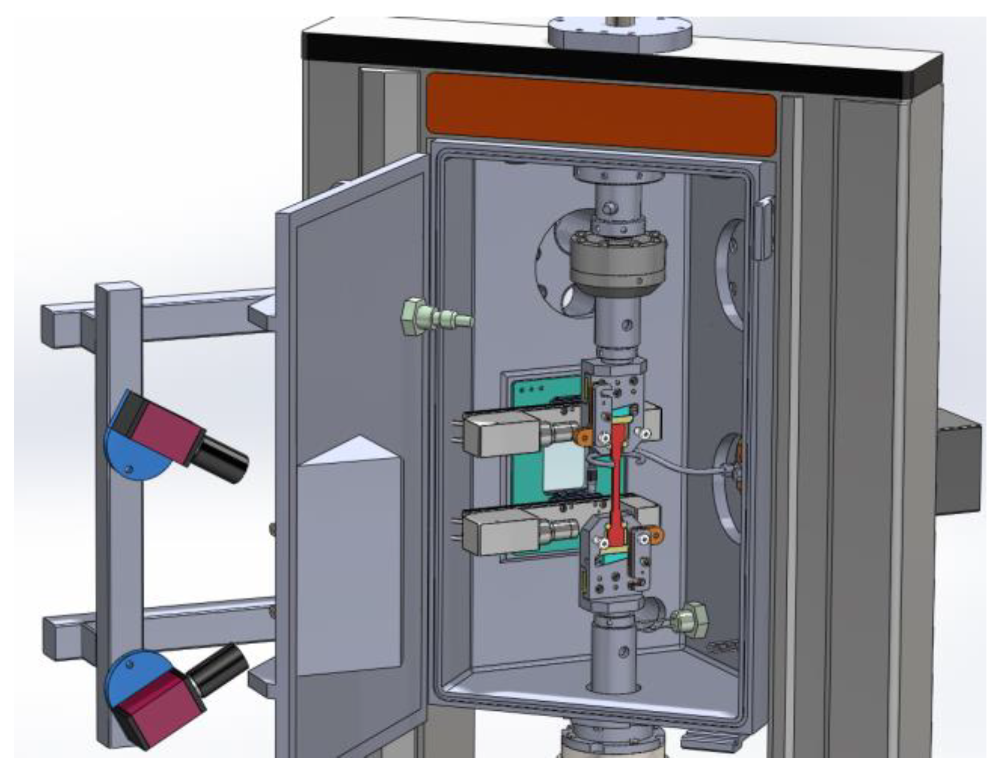
2. Machine Overview
3. System of Temperature Control
3.1. Heating by Joule effect
3.2. Proportional–Integral–Derivative Controller (PID) for Temperature Regulation
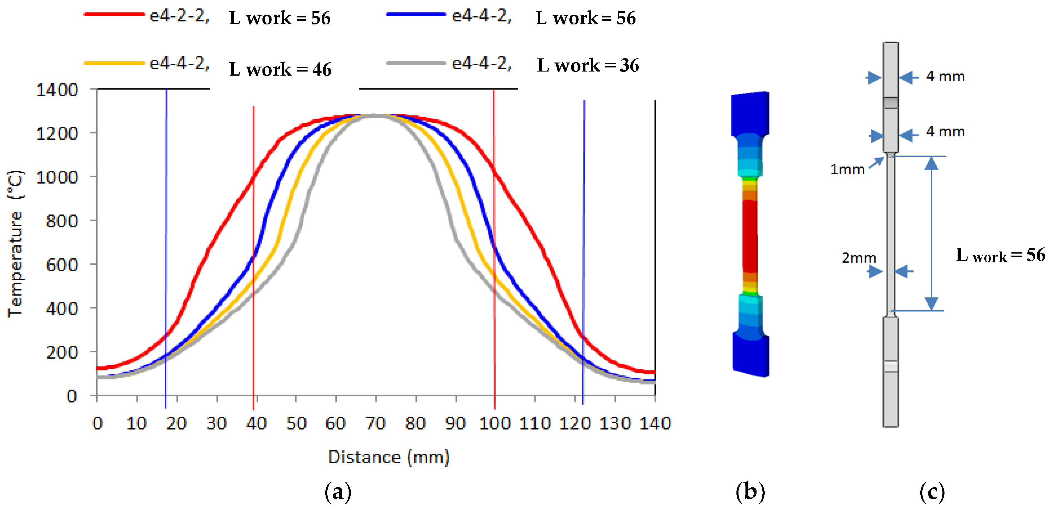
4. Optimization of Specimen Design
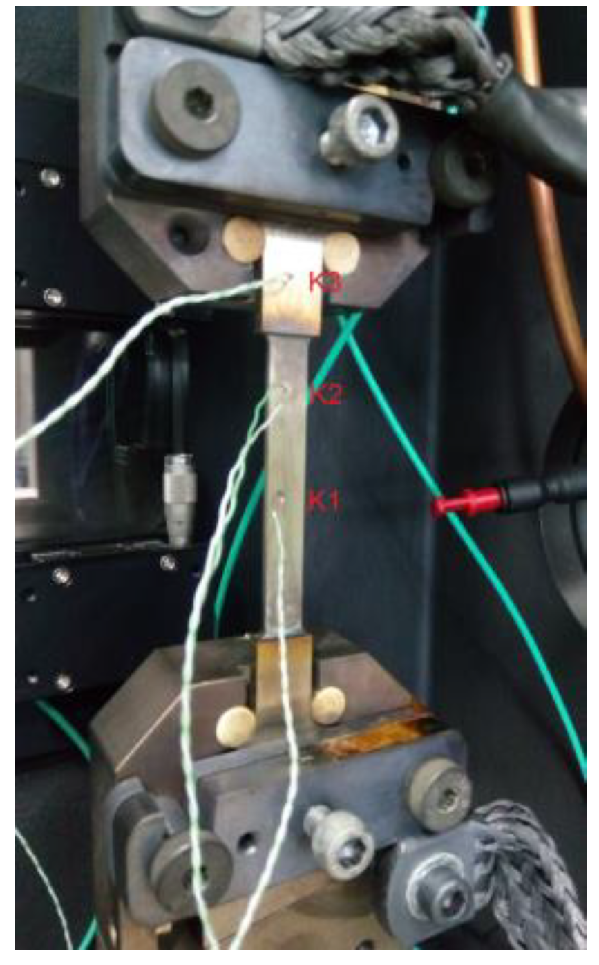
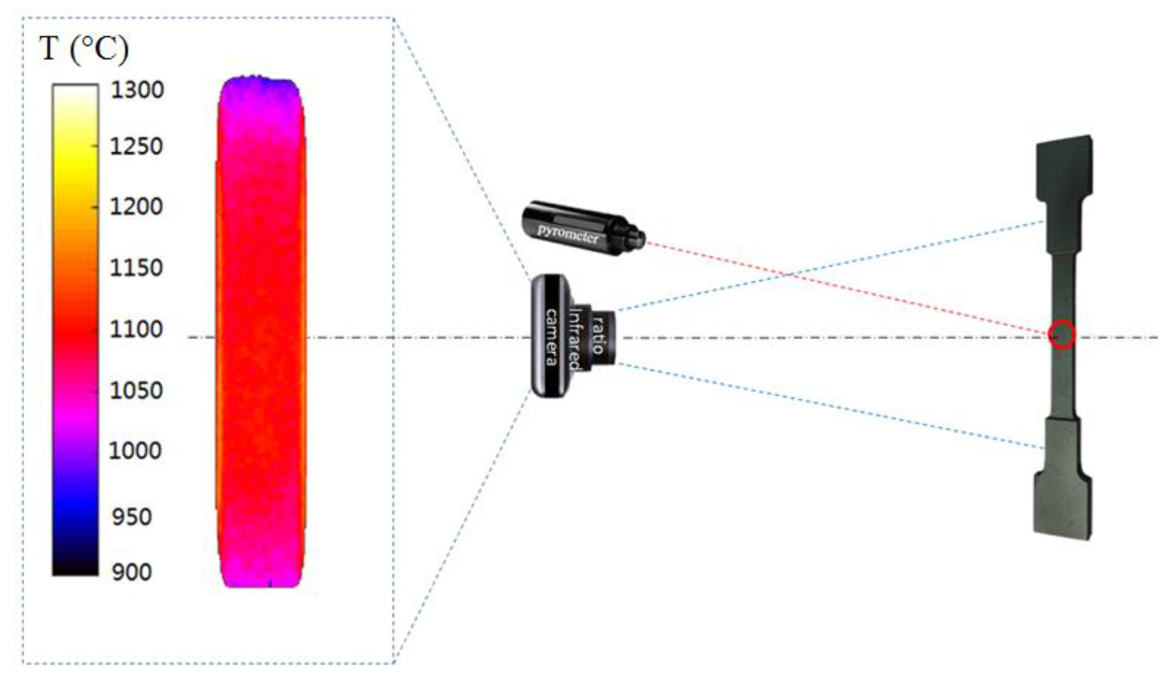
5. Temperature Measurement
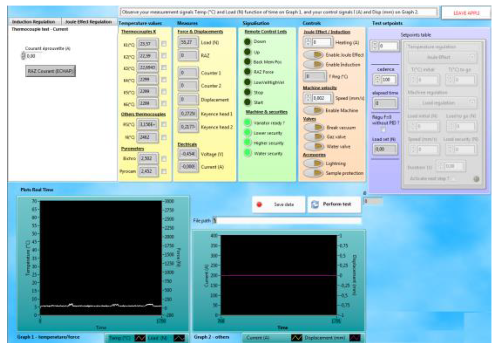
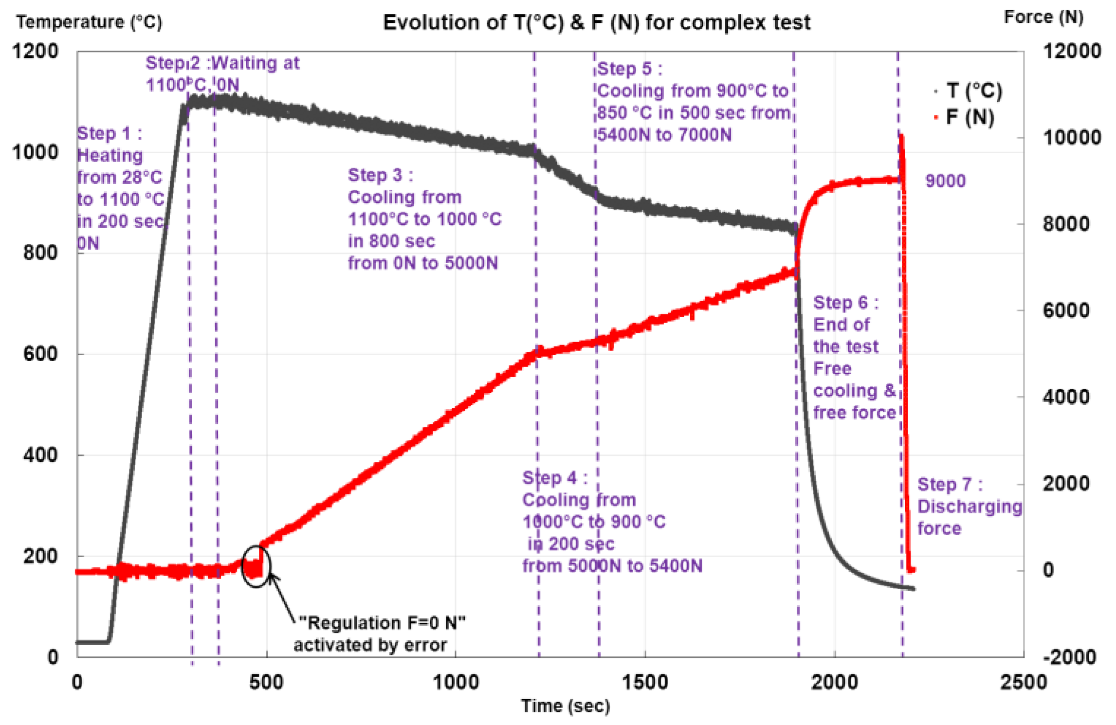
6. Monitoring Design and Experimental Tests
7. Discussions and Conclusions
References
- Harrison, N.J.; Todd, I.; Mumtaz, K. Reduction of micro-cracking in nickel superalloys processed by Selective Laser Melting: A fundamental alloy design approach. Acta Mater. 2015, 94, 59–68. [Google Scholar] [CrossRef]
- Koshikawa, T.; Bellet, M.; Gandin, C.A.; Yamamura, H.; Bobadilla, M. Study of hot tearing during steel solidification through ingot punching test and its numerical simulation. Metall. Mater. Trans. A 2016, 47, 4053–4067. [Google Scholar] [CrossRef]
- Zhang, C.; Bellet, M.; Bobadilla, M.; Shen, H.; Liu, B. A Coupled Electrical–Thermal–Mechanical Modeling of Gleeble Tensile Tests for Ultra-High-Strength (UHS) Steel at a High Temperature. Metall. Mater. Trans. A 2010, 41, 2304–2317. [Google Scholar] [CrossRef]
- Maisonnettea, D.; Sueryb, M.; Nelias, D.; Chaudet, P.; Epicier, T. Effects of heat treatments on the microstructure and mechanical properties of a 6061 aluminium alloy. Mater. Sci. Eng. A 2011, 528, 2718–2724. [Google Scholar] [CrossRef]
- Pradille, C.; Bellet, M.; Chastel, Y. A Laser Speckle Method for Measuring Displacement Field. Application to Resistance Heating Tensile Test on Steel. Appl. Mech. Mater. 2010, 24–25, 135–140. [Google Scholar] [CrossRef]
- Pradille, C. Vers une Meilleure Compréhension et Caractérisation du Comportement des Aciers à très Haute Température. Ph.D. Thesis, École Nationale Supérieure des Mines de Paris, Paris, France, 2011. [Google Scholar]


Publisher’s Note: MDPI stays neutral with regard to jurisdictional claims in published maps and institutional affiliations. |
© 2018 by the authors. Licensee MDPI, Basel, Switzerland. This article is an open access article distributed under the terms and conditions of the Creative Commons Attribution (CC BY) license (https://creativecommons.org/licenses/by/4.0/).
Share and Cite
Pignolet, A.; Combeaud, C.; Fournier, F.; Fiorucci, G.; Pradille, C.; Zhang, Y.; Pinto-Mora, A.; Gao, F.; Bellet, M. Experimental Approach for Metals Mechanical Behavior Characterization at High Temperature: Development of a Complex Tensile Test Machine. Proceedings 2018, 2, 355. https://doi.org/10.3390/ICEM18-05207
Pignolet A, Combeaud C, Fournier F, Fiorucci G, Pradille C, Zhang Y, Pinto-Mora A, Gao F, Bellet M. Experimental Approach for Metals Mechanical Behavior Characterization at High Temperature: Development of a Complex Tensile Test Machine. Proceedings. 2018; 2(8):355. https://doi.org/10.3390/ICEM18-05207
Chicago/Turabian StylePignolet, Arnaud, Christelle Combeaud, Francis Fournier, Gilbert Fiorucci, Christophe Pradille, Yancheng Zhang, Aliz Pinto-Mora, Feng Gao, and Michel Bellet. 2018. "Experimental Approach for Metals Mechanical Behavior Characterization at High Temperature: Development of a Complex Tensile Test Machine" Proceedings 2, no. 8: 355. https://doi.org/10.3390/ICEM18-05207
APA StylePignolet, A., Combeaud, C., Fournier, F., Fiorucci, G., Pradille, C., Zhang, Y., Pinto-Mora, A., Gao, F., & Bellet, M. (2018). Experimental Approach for Metals Mechanical Behavior Characterization at High Temperature: Development of a Complex Tensile Test Machine. Proceedings, 2(8), 355. https://doi.org/10.3390/ICEM18-05207