Proceeding Paper

The Cause Estimation of Damages in Pathein Suspension Bridge Based on Vibration Measurements †

Institute of Industrial Science, The University of Tokyo, Tokyo 153-8505, Japan
*
Author to whom correspondence should be addressed.
Presented at the 18th International Conference on Experimental Mechanics, Brussels, Belgium, 1–5 July 2018.
Proceedings 2018, 2(8), 379; https://doi.org/10.3390/ICEM18-05209
Published: 9 May 2018
(This article belongs to the Proceedings of The 18th International Conference on Experimental Mechanics)

Abstract

:
Pathein suspension bridge situated in Pathein City in the south of Myanmar has shown various symptoms of damage, and the safety of the bridge is questionable. The authorities concerned reported that the bridge has undergone severe deterioration since its construction, involving the towers’ inclination, excessive deflections, bearing failure, heavy corrosion of main cables and hangers, hangers’ inclination, and slippage of clamps. The deformed shape of the stiffening girder was found to be unusual, with maximum deflection nearer to the towers; however, in a single span bridge, such as Pathein Bridge, the maximum deflection is expected to be at mid-span. This paper will explain the possible reasons for the unusual excessive deformations in the stiffening girder and bearing failure. The tension force of hangers was estimated based on vibration measurements, and the distribution of hangers’ tension force along the bridge’s span was found to be non-uniform with low-tension force in hangers closer to the towers. The non-uniform distribution of the hangers’ tension force is possibly due to shortcomings of the design of the cable system. The towers’ inclination has caused the road level to drop down; however, the unusual deformations in stiffening girder are attributed to the non-uniform distribution of the tension force in the hangers. Low-tension force in the hangers near the towers caused the bearing to carry excessive force, which eventually caused the bearing to fail; the bearing was rehabilitated by adding steel rollers.

1. Introduction

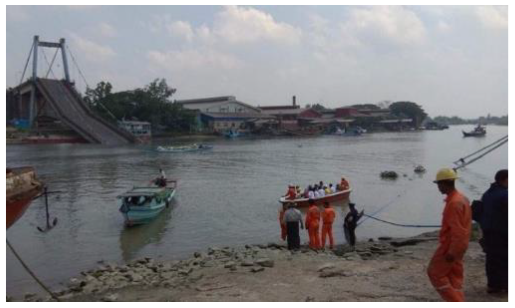
1.1. Bridges’ Condition in Myanmar

A survey conducted in 2012 by Japan Infrastructure Partners pointed out that many bridges constructed in Myanmar recently have already shown severe deteriorations and require countermeasures [1]. On 1 April 2018, Myaungmya Suspension Bridge located in Ayeyawady region in south of Myanmar collapsed, and two persons were reported missing [2]. The bridge was significantly deteriorated and the traffic was restricted to one lane [1]; however, the safety of the bridge was not accurately assessed. Figure 1 shows Myaungmya Bridge after the collapse.

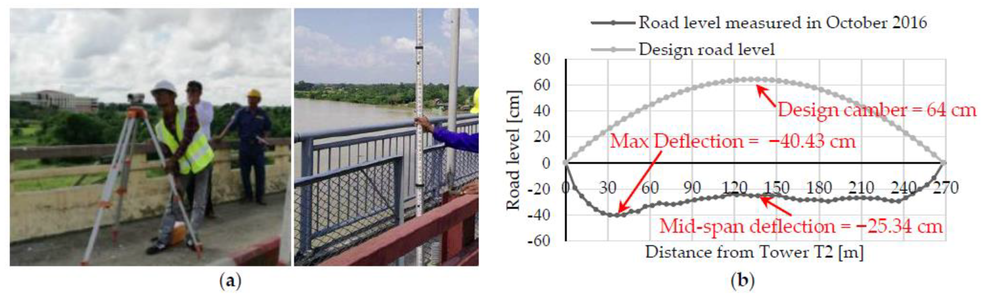
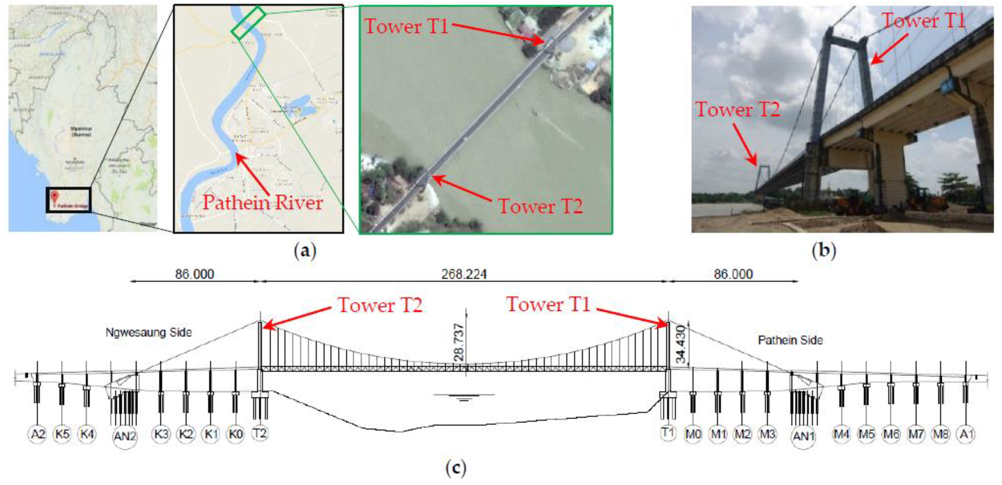
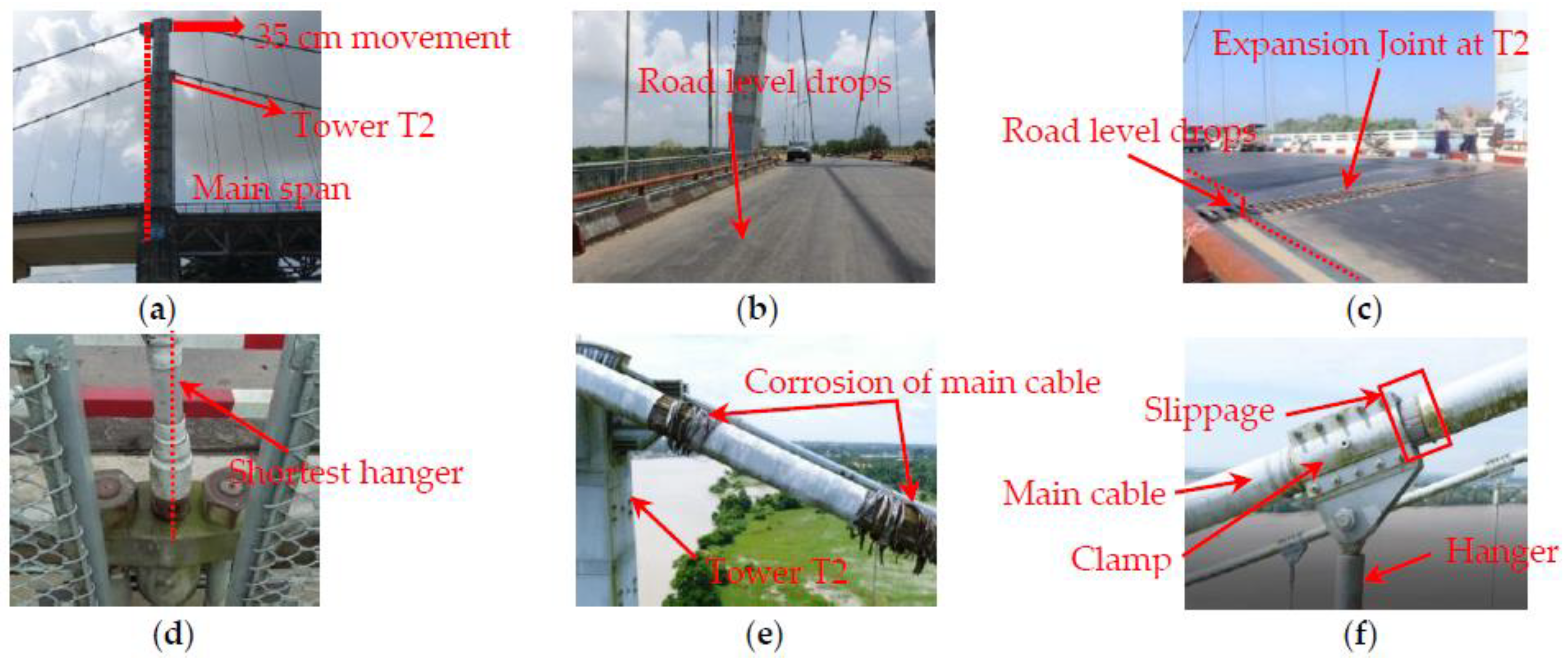
1.2. Pathein Suspension Bridge: Current Condition and Objectives

Pathein Suspension Bridge, situated in Pathein city in the south of Myanmar, was constructed in 2004. The bridge is crossing Pathein River and is believed to have significant importance for the traffic crossing the river. The bridge consists of one main span of 268.224 m and two side spans of 86 m. The bridge’s main span consists of a stiffening truss suspended by 52 hangers on each side of the bridge, while the side spans consist of precast concrete girders; Figure 2 shows an overview of the bridge. It is noticeable that in the real bridge, hangers exist on side spans as well. However, they do not exist in the design drawings; they were constructed for an aesthetic purpose, and they carry no force.
Pathein Bridge has shown various deteriorations; the safety of the bridge is questionable and an immediate assessment and monitoring is crucial. Visual investigations and investigations using drones were carried out in July 2017; the damages of the bridge can be placed into six categories as shown in Figure 3. The top of towers T2 and T1 moved 35 and 21 cm, respectively, towards the main span; excessive deflections in stiffening girder; failure of the bearing downstream of T2; heavy corrosion of main cables and hangers; hangers’ inclination; slippage of clamps. It is notable that the deflection of the stiffening girder is unusual, with maximum deflection of 40.43 cm near tower T2; however, maximum deflection is normally found at the mid-span in single span bridges; Figure 4 shows the road level of Pathein Bridge measured in October 2016.
Considering the damages that the bridge is undergoing, and the importance of the bridge for the traffic over the river, it is important to estimate the causes of the damage, assess the current safety, and monitor any further damage. However, as a first step, the objective of this paper is to investigate the causes of the damages to pave the way for the safety assessment of the bridge.

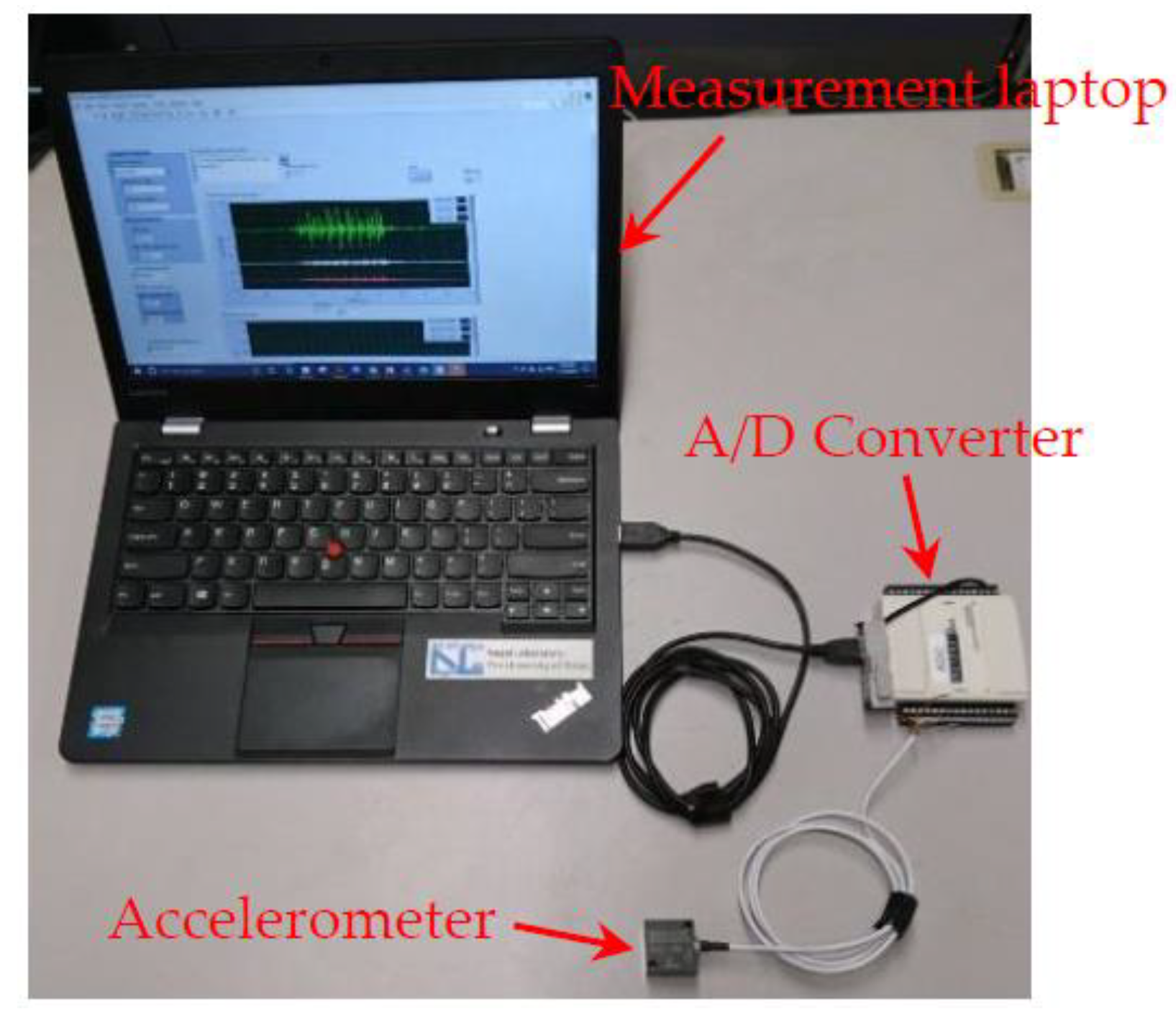
2. Vibration Measurements

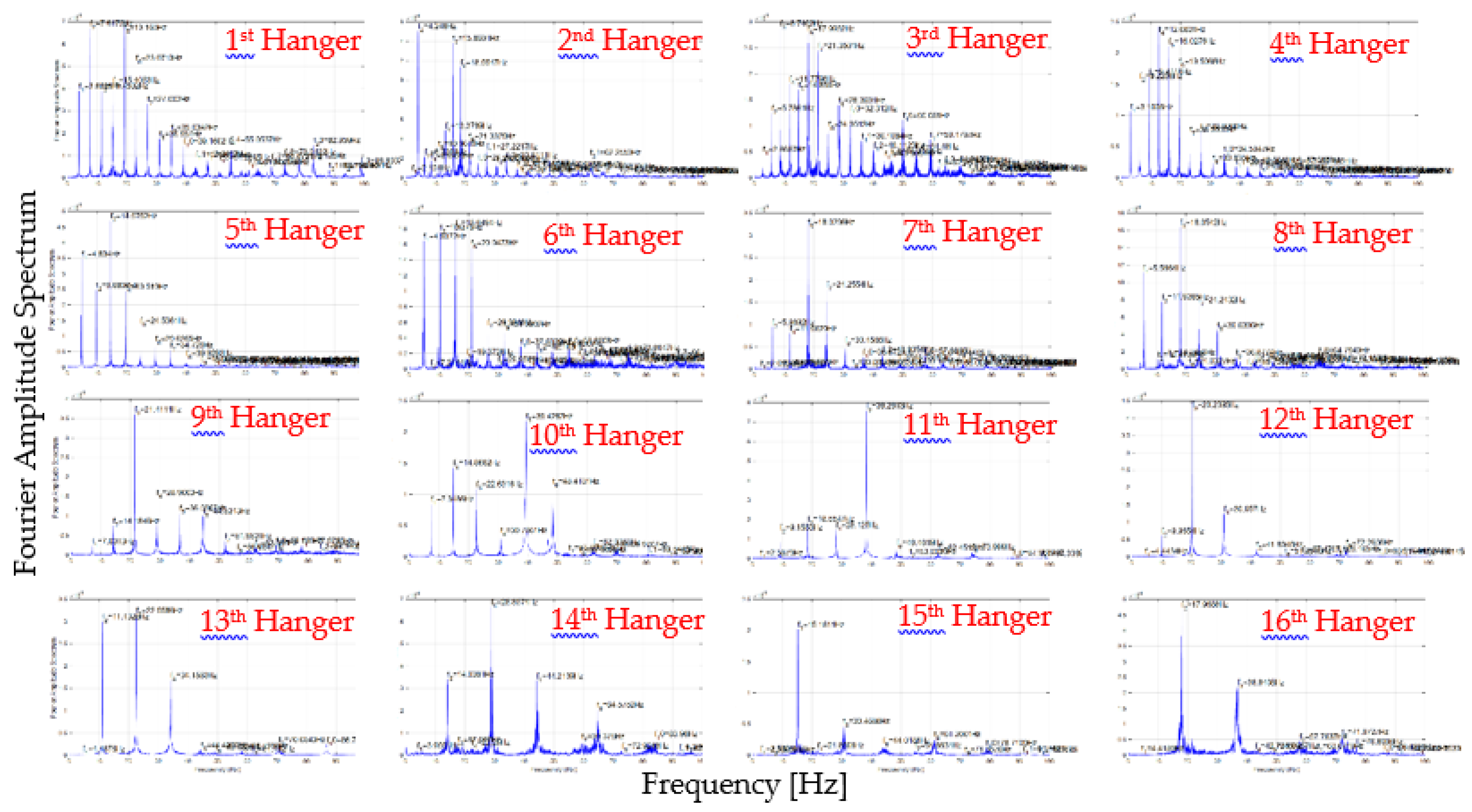
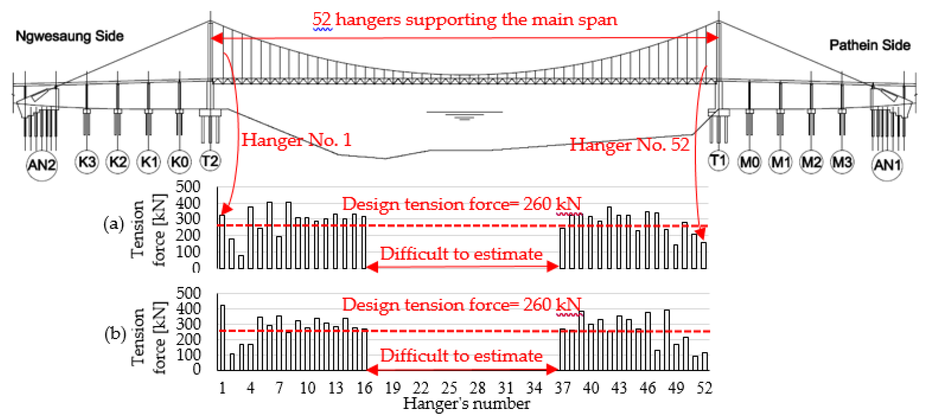
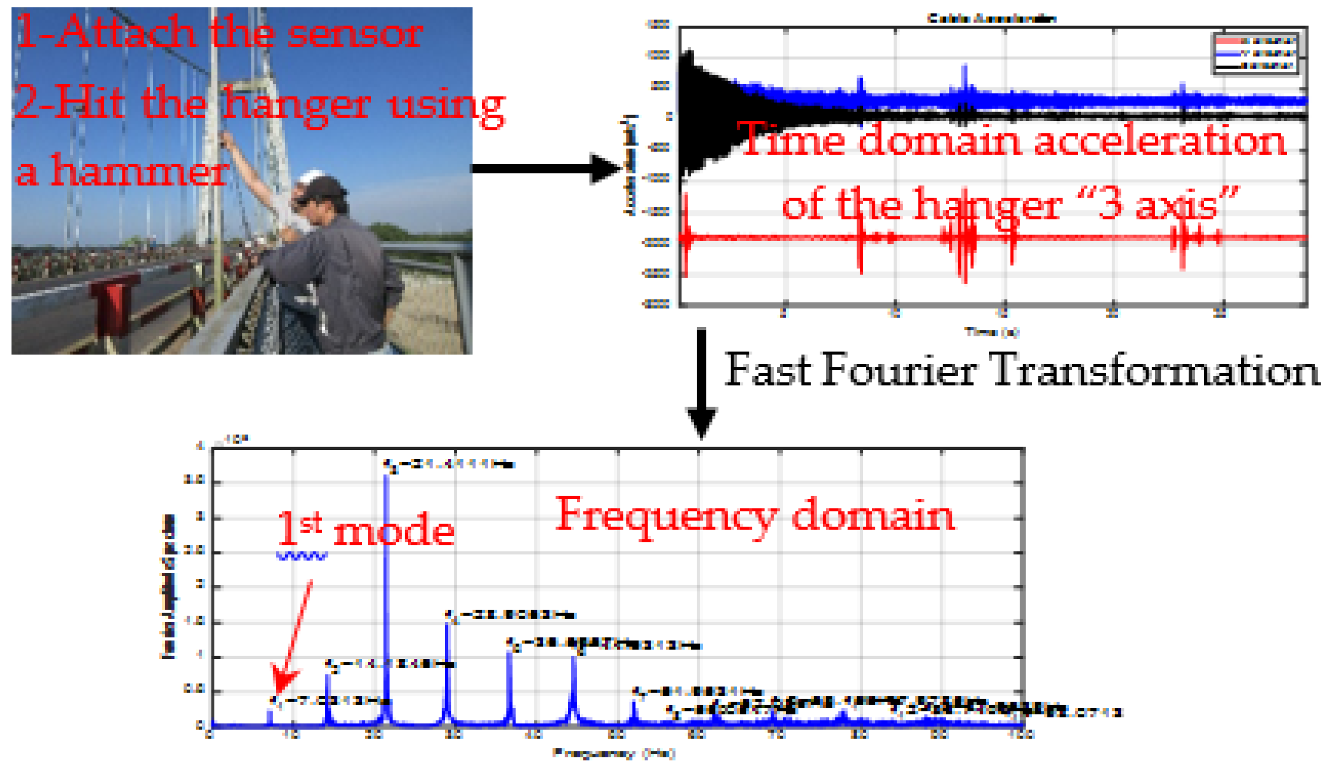
2.1. Estimation of Hangers’ Tension Force: Theory and Application

Considering damage the level and large deformations in Pathein Bridge, the distribution of the hangers’ tension force has been called into question; therefore, it was decided to estimate the hangers’ force to understand how the damage and deformations influence the hangers’ tension force distribution along the bridge’s span. Internal force estimation by Lift-off tests is expensive; moreover, it may cause structural damage in the tested bridge [3]. In practice, internal force estimation using vibration methods has attracted increasing attention because of its simplicity, speediness, and acceptable accuracy if used properly [4]. Vibration measurement is widely used to estimate cables’ tension force and to assess the condition of cables in cable-supported bridges [5].
Many vibration-based methods have been developed to estimate the tension force of the cables while also considering the dynamic characteristics and physical properties of cables [6]; the dynamic characteristic of interest is mainly the natural frequency. Zui et al. (1996) introduced a practical formula to estimate the tension force of the cables considering both sag and flexural effects [7]; the formula was validated by experiments under different conditions of sag and flexural rigidity. Equations (1)–(3) show the relationship between the tension force of a cable, the first mode natural frequency of the cable, and the physical properties of the cable as per Zui et al. (1996):
T = 4 w 𝘨 ( f 1 l   ) 2 [ 1 2.20   c o e f . 1   f 1 0.550     ( c o e f . 1 f 1 ) 2 ]   ;       ( 17 T / E I l ) ,      
T = 4 w 𝘨 ( f 1 l ) 2 [ 0.865 11.60     ( c o e f . 1 f 1 ) 2 ]   ;       ( 6 T / E I l 17 ) ,            
T = 4 w 𝘨 ( f 1 l ) 2 [ 0.828 10.50     ( c o e f . 1 f 1 ) 2 ]   ;       ( 0 T / E I l 6 ) ,            
in which T denotes the tension force in kN, w denotes weight of cable per unit length kN/m, f 1 denotes the first mode natural frequency in Hz, 𝘨 denotes gravitational acceleration m/ s 2 ,   l denotes the length of the cable in m, EI denotes flexural rigidity of the cable kN. m 2 , and c o e f . 1 = ( E I 𝘨 ) / ( w l 4 ) . By measuring the frequency of a cable, and calculating other structural parameters, tension force estimation is straightforward.

2.2. Conducted Measurements

Vibration measurements were conducted in November 2017 to estimate the hangers’ tension force distribution along the bridge. The measurements were conducted using 3-axis piezoelectric accelerometers; Figure 5 shows the measurements’ system. The accelerometer was attached to the hangers using double-sided tape; then, the hangers were excited by hitting them several times using a rubber hammer. The data were collected with a sampling rate of 400 Hz, and the acceleration of the hangers in the direction of bridge axis was considered for the analysis. The data were recorded for 60 s for each hanger, and Fast Fourier Transformation (FFT) was calculated to estimate the frequency property of the recorded acceleration; Figure 6 shows the measurements’ procedures. The 1st mode frequency of 32 hangers out of 52 hangers of each side was successfully estimated; however, the shortest 20 hangers were difficult to estimate and further measurements are required. Figure 7 shows the frequency domain plots of the first 16 hangers in DS (1st hanger is closest to T2).

3. Results and Discussion

3.1. Estimation of Hangers’ Tension Force: Results

The main objective of the vibration measurements has been to estimate the tension force of the hangers by measuring the first mode natural frequency of the hangers. The natural frequencies of the long hangers (more than 12 m) show good agreement with a straight line as f n = n . f 1   for mode order n; this indicates that the flexural rigidity has a small influence on the natural frequencies. However, the shorter (less than 12 m) hangers’ frequencies show nonlinearity, and the flexural rigidity should be considered. The tension force of the hangers was estimated using the practical formula of Zui et al. (1996), since it considers both sag and flexural rigidity of the cable. Figure 8 shows the distribution of the tension force for both upstream and downstream, results of only 32 hangers were estimated due to difficulties in evaluating the results of the shortest hangers.

3.2. Estimation of the Cause of the Damages

The geometry of the main cable is usually chosen so that it coincides with the funicular curve of the total dead load; this is to make sure that both towers and girder are moment-free at the mean temperature. The design profile of the main cable of Pathein bridge was found not to fit the funicular shape; consequently, the manufacturer prepared hangers in longer lengths than the required length to maintain the road level as per design profile (vertical curve radius R = 14,000 m). The error of the hangers’ length preparation was maximum (75 cm) in the longest hangers (27.2 m), while it was negligible in shortest hangers. Considering the distribution of the tension force along the bridge (Figure 8), it is noticeable that hangers near the towers (except hanger 1 in US and DS) carry lower tension force compared to the design tension force (260 kN); this is likely due to the shortcomings of the design of the main cables and hangers.
The low-tension force near the towers caused an excessive downward force to be transferred to bearings, which is not designed to carry such downward force. The failure of the bearing of the downstream of Tower T2 is possibly due to the excessive force that had to be carried by hangers near Tower T2. Once the bearing failed and the road level dropped at tower T2, the first hangers (hanger 1 in Figure 8) carried larger force. The bridge was lifted up at tower T2, and the bearing was rehabilitated and supported by adding new rollers to support the excessive force. The bearing at the other side (at tower T1) is also suspected to fail, since it is undergoing similar conditions; as a precaution, new steel rollers were added to support the bridge in case of any future failure of the bearing. The maintenance crew welded the bearings at tower T1, and no rotation is allowed anymore; further study on how fixation of the bearings can affect the behavior of the bridge is needed.
Towers’ inclination caused the road level of Pathein Bridge to drop down; however, the maximum deflection is expected to be mid-span. Preparation of hangers in longer lengths caused additional deflections in the stiffening girder. The error in hangers’ length preparation was maximum in hangers near the towers, while it was negligible in hangers near mid-span; therefore, it is reasonable that deflections are larger near towers. The final deflection is a combination of the deflection caused by towers’ inclination and the deflection caused by the shortcoming of hangers’ length design; the maximum deflection happened to be near tower T2.

4. Conclusions

The shortcoming of the design of the main cables caused the hangers to be prepared in longer lengths than required, which resulted in non-uniform distribution of hangers’ tension force with low-tension force near the towers. The low-tension force of hangers near the towers caused excessive forces to be transferred to bearings; the failure of the bearing at the downstream of tower T2 is possibly due to this additional force. Preparation of hangers in longer lengths caused exceptional deformations in the stiffening girder, coupled with the deflections caused by Towers’ inclination; the final deformed shape of the stiffening girder was found to be unusual, with maximum deflection near tower T2.

5. Future Works

We seek to investigate the cause of the other damages (Towers’ inclination, hangers’ inclination, corrosion of cable system, and slippage of clamps) and monitor the inclination of the towers. The final goal of the project is to judge the safety of the bridge for the upcoming ten years; to achieve this, the causes of the damage and the progress of the damage are needed to make the final judgment on the current and future safety of the bridge.

Author Contributions

O.A.H. and T.M. designed the measurements; O.A.H., T.M., and K.M. performed the measurements; O.A.H reviewed the design drawings of the bridge; O.A.H analyzed the data; T.M. reviewed the analysis; O.A.H., T.M., K.M., and K.N concluded the analysis results; O.A.H wrote the paper; T.M., K.M., and K.N reviewed the paper.

Acknowledgments

This research was supported by Science and Technology Research Partnership for Sustainable Development (SATREPS); Japan Science and Technology Agency (JST)/Japan International Cooperation Agency (JICA); Council for Science, Technology, and Innovation (CSTI); Cross-ministerial Strategic Innovation Promotion Program (SIP); and “Infrastructure Maintenance, Renewal, and Management Technology” (Funding agency: JST).

Conflicts of Interest

The authors declare no conflict of interest.

References

  1. Japan Infrastructure Partners. Current Situation and Issues of Myanmar’s Bridge Work; Japan Infrastructure Partners: Tokyo, Japan, 2012. [Google Scholar]
  2. Bridge Incident: Myaungmya Bridge Collapses|Myanmar International TV. Available online: http://www.myanmarinternationaltv.com/news/bridge-incident-myaungmya-bridge-collapses (accessed on 14 April 2018).
  3. Geier, R.; de Roeck, G.; Flesch, R. Accurate cable force determination using ambient vibration measurements. Struct. Infrastruct. Eng. 2006, 2, 43–52. [Google Scholar] [CrossRef]
  4. Kim, B.H.; Park, T. Estimation of cable tension force using the frequency-based system identification method. J. Sound Vib. 2007, 304, 660–676. [Google Scholar] [CrossRef]
  5. Liao, W.Y.; Ni, Y.Q.; Zheng, G. Tension Force and Structural Parameter Identification of Bridge Cables. Adv. Struct. Eng. 2012, 15, 983–995. [Google Scholar] [CrossRef]
  6. Debora, S.N.; Parivallal2, S.; Ravisankar, K.; Hemalatha, G. Evaluation of Cable Tension Using Vibration Based Methodologies for Health Monitoring Of Structures. Int. J. Innov. Res. Sci. Eng. Technol. 2007, 4, 506–514. [Google Scholar]
  7. Shinke, T.; Hironaka, K.; Zui, H.; Nishimura, H. Practical Formulas for Estimation of Cable Tension By Vibration Method. J. Struct. Eng. 1996, 122, 651–656. [Google Scholar] [CrossRef]
Figure 1. Myaungmya Bridge after the collapse.
Proceedings 02 00379 g001
Figure 2. Pathein Bridge. (a) Location of the bridge on Myanmar’s map, (b) picture of the bridge, and (c) elevation of the bridge as per design drawings.
Proceedings 02 00379 g002
Figure 3. The damages in Pathein Bridge. (a) Inclination of tower T2; (b) road level sinking down; (c) road level drops down after the bearing failed; (d) inclination of hangers; (e) corrosion of the main cable; and (f) slippage of clamps.
Proceedings 02 00379 g003
Figure 4. (a) During the measurement of road level and (b) design road level and measured road level.
Proceedings 02 00379 g004
Figure 5. Measurements’ system.
Proceedings 02 00379 g005
Figure 6. Measurements’ procedure.
Proceedings 02 00379 g006
Figure 7. The frequency domain plots of the first 16 hangers in DS (1st hanger is closest to T2).
Proceedings 02 00379 g007
Figure 8. Hangers’ tension force distribution of Pathein Bridge. (a) Tension force of hangers of upstream; (b) tension force of hangers of downstream.
Proceedings 02 00379 g008
Publisher’s Note: MDPI stays neutral with regard to jurisdictional claims in published maps and institutional affiliations.

