1. Introduction
Multiple photogrammetry applications are based on Unmanned Aerial Systems (UAS) due to cost efficient data acquisition and high spatio-temporal resolution imagery. Widely used in various fields like land surveying and construction, ground control points (GCPs) can greatly increase the accuracy of the 3D information and their measurement is an important aspect of georeferencing the UAS image blocks. Ground control points are used in the process of indirect georeferencing the UAS images, a minimum of three ground control points being required, although increasing the number of GCPs will lead to higher accuracy of the final results i.e., point cloud, 3D mesh, orthomosaic or digital surface model (DSM). Moreover, exceeding the number of ground control points is a time-consuming process, both in the field and computationally.
A series of studies have been conducted to determine the optimum number of ground control points, but mainly for georeferencing the DSM [
1,
2,
3,
4,
5], the orthoimage [
2,
3,
6,
7] and the point clouds [
8] generated by processing the UAS images. Tahar et al. [
7] studied the influence of the number and distribution of GCPs for georeferencing the UAS images, but he did not use the SfM (structure from motion) algorithm for image matching. It was demonstrated that increasing the number of ground control points will increase the accuracy of the final products [
1,
2]. Even so, the accuracy of the final products derived from UAS images is influenced by different factors, such as: camera’s focal length, flight altitude, camera orientation, image quality, processing software, type of UAS system (fixed wind or rotary wind), and the precision with which targets can be measured and matched [
1,
8]. Each study contributes to the improvement in the product obtained by UAS technology.
The main aim of this study is to determine the optimum number of ground control points in order to georeference a block of nadiral UAS images taken at two heights, in different scenarios and using two different software i.e., Pix4D Mapper software (commercialized by Pix4D and widely used in the photogrammetric and remote sensing community) and 3DF Zephyr Pro software (that promises a lot in the 3D reconstruction area, which is commercialized by 3Dflow) and to assess the accuracy of the final products i.e., dense point cloud and mesh surface (not only the DSM as mentioned in other studies [
1,
2,
3,
4,
5]) by comparing the results with terrestrial laser scanner (TLS) point cloud and total station measurements, for three cases: using 3 GCPs and the determined optimum number of GCPs. Also, as already mentioned in Tonkin et al. [
5], the accuracy of GCPs directly influence the accuracy of the final products; thus, in this study all GCPs were measured with millimetre precision, using a total station in a local coordinate system and by designing a spatial geodetic network.
In this study, an area of about 1 ha was photographed with a low-cost UAS, namely, the DJI Phantom 3 Standard, at two different heights and a number of 50 ground control points, uniformly distributed over the study area, were measured using a total station.
2. Study Area
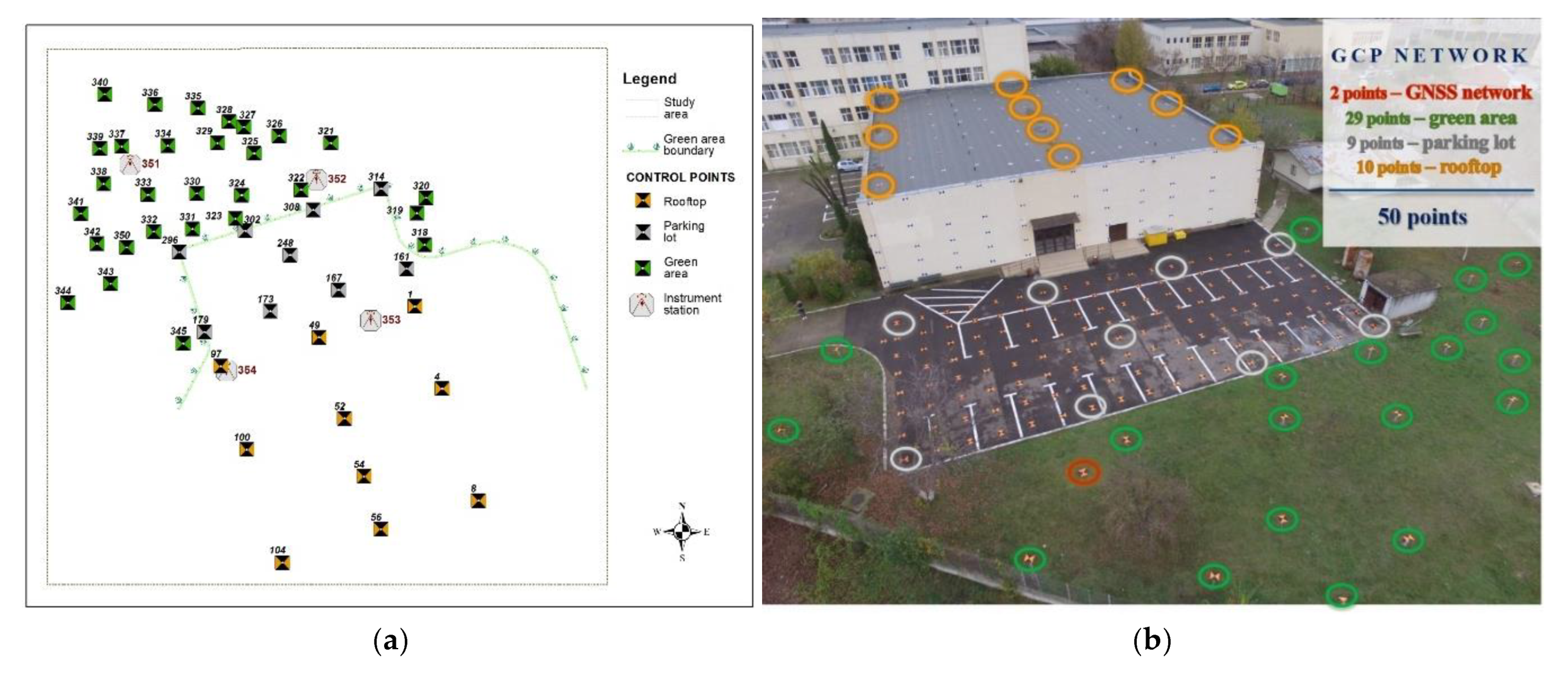
The study area is located near the Faculty of Hydrotechnical Engineering, Geodesy and Environmental Engineering at the “Gheorghe Asachi” Technical University of Iasi, Romania, it is about 1 ha and covers the building roof, the parking lot and the green area in the vicinity.
3. Materials and Methods
3.1. Measurement of Ground Control Points (GCPs)
For this project, the solution chosen was to design a spatial geodetic network determined by GNSS technology, thus, providing homogeneous and unitary precision for all three components of spatial positioning. The spatial geodetic network was designed with four points, two of which were grounded in the green area behind the Faculty of Hydrotechnical Engineering, Geodesy and Environmental Engineering, and the other two were located on the roof in the northern part of the building. For the present research, a local reference and coordinate system was adopted.
There were 50 uniformly distributed grounded points in the study area: 29 points in the green space (reinforced concrete poles to ensure different heights), 2 points of the GNSS network (concrete), nine points in the parking lot (metallic bolts) and 10 points on the roof (marked with paint) (
Figure 1).
Each new point was double measured using a mini prism from the ends of a GNSS base. For determining the final spatial coordinates of the detail points, the weighted indirect compensation model was applied for each new point, obtaining a total accuracy of a few millimetres. To assure their visibility on the UAS images, the points were marked using plexiglass plates that were drawn with two black and orange triangles, 3 mm thick, 40 cm × 40 cm, with a central hole of 5 mm diameter.
3.2. Data Acquisition
The area of interest was photographed with a DJI Phantom 3 Standard, a low-cost UAS, at two different heights: 28 m and 35 m above ground. The low-cost UAS platform has a built-in digital camera equipped with a 6.2031 mm by 4.6515 mm image sensor capable of taking images with a resolution of 12 MP and 4000 × 3000 pixels. The flight planning was made with Pix4D software, choosing a longitudinal and transversal overlap of 80% and 40%, respectively, the camera being oriented in a nadiral position. For the height of 28 m, the flight was made in double grid, 122 images being acquired with 1 cm GSD while for 35 m, the flight was made in single grid, 51 images with the GSD of 1.24 cm being acquired. In order to assess the accuracy of the point clouds and the mesh surfaces automatically generated based on UAS images, a comparison was done with a TLS point cloud. This resulted from registering four point clouds obtained with Maptek I-Site 8820 terrestrial laser scanner from the ends of the two GNSS bases, using the direct georeferencing process.
3.3. Data Processing
As mentioned before, the proposed tests were made taking into account different scenarios. In all the scenarios, the UAS images were processed with a minimum number of ground control points while the 47 remaining control points served as check points (CP) for accuracy assessment. For the evaluation, the CPs were manually measured on each oriented image, the coordinates being compared with the ones determined with high precision by the GNSS technology. Then, the number of GCPs was gradually increased up to 40, with the accuracy being checked on the remaining 10 CPs. The Euclidian distance between the two coordinate sets for a point was calculated based on the measured coordinates, followed by the determination of the root mean square error (RMSE).
For UAS image processing using the 3DF Zephyr Pro software, the images were imported into the software and the project was processed without specifying the type of camera and the calibration parameters, so for the interior and exterior orientation parameters for each camera position an approximation was made based on the EXIF information. All the GCPs were manually measured on each oriented image that they appeared on (minimum 3). The file containing this information was exported and based on this project, new ones were created (a project for 3 GCPs and 47 CPs, one for 4 GCPs and 46 CPs etc.), each time importing the same image measurements for the GCPs. In order to bring the results into the local coordinate system, the option “Scale model with control points” was chosen. In the following stage, a table with the coordinates of all the GCPs appears and the “Constraint” and “Control” boxes were checked for the control points (3–40 control points) and only the “Control” box was checked for the points serving as check points (47–10 check points). The constraints confidence weight was left as the default value i.e., 50%. Furthermore, the “Perform Bundle Adjustment” option was selected and for “Advanced settings” the interior orientation with radial and tangential parameters adjustment was chosen. After running the bundle adjustment process, the errors for each control and check point were displayed in pixels and in meters. The coordinates of all 50 GCPs were exported and compared with the coordinates determined with high precision. The options “Aerial” for “Category” and “Default” for “Presets” were chosen in order to generate the dense point cloud. For the mesh surface creation, the options “Aerial” for “Category” and “Default-Sharp Features” for “Presets” were chosen. To perform the third scenario with the 3DF Zephyr Pro software, i.e., using a free-network approach in the bundle adjustment and only at the end of the bundle adjustment process, the GCPs have to be used for applying a similarity (Helmert) transformation in order to bring the image network results into the desired reference coordinate system, therefore, the option “Perform Bundle Adjustment” remains unchecked.
Processing in Pix4D implies several steps, but mainly consists of importing the desired images into a new project and for the “Image properties” and “Output/GCP Coordinate System”, the Arbitrary (m) coordinate system was selected, and the “Geolocation” option was not applied in the process. Therefore, 3D Maps was chosen as the “Template”, as it was suitable for the project’s applications (it is recommended for nadir flights with a high overlap and it generates the point cloud, 3D mesh, DSM and the orthomosaic as deliverables). As an advanced processing option, for the matching strategy geometrically verified matching was used. With “GCP/MTP Manager”, the file with the control points was imported as well as the corresponding marks for each image (the same marks exported from the 3DF Zephyr Pro software), and after the horizontal and vertical accuracy (m) was changed to 0.002, the involved GCP were selected by changing the “Type” while the remaining points were left as Manual Tie Points (MTP). After the initial processing, for the second stage, point cloud and mesh generation, the default options were applied.
4. Results
4.1. Results Corresponding to 28 m Height Flight
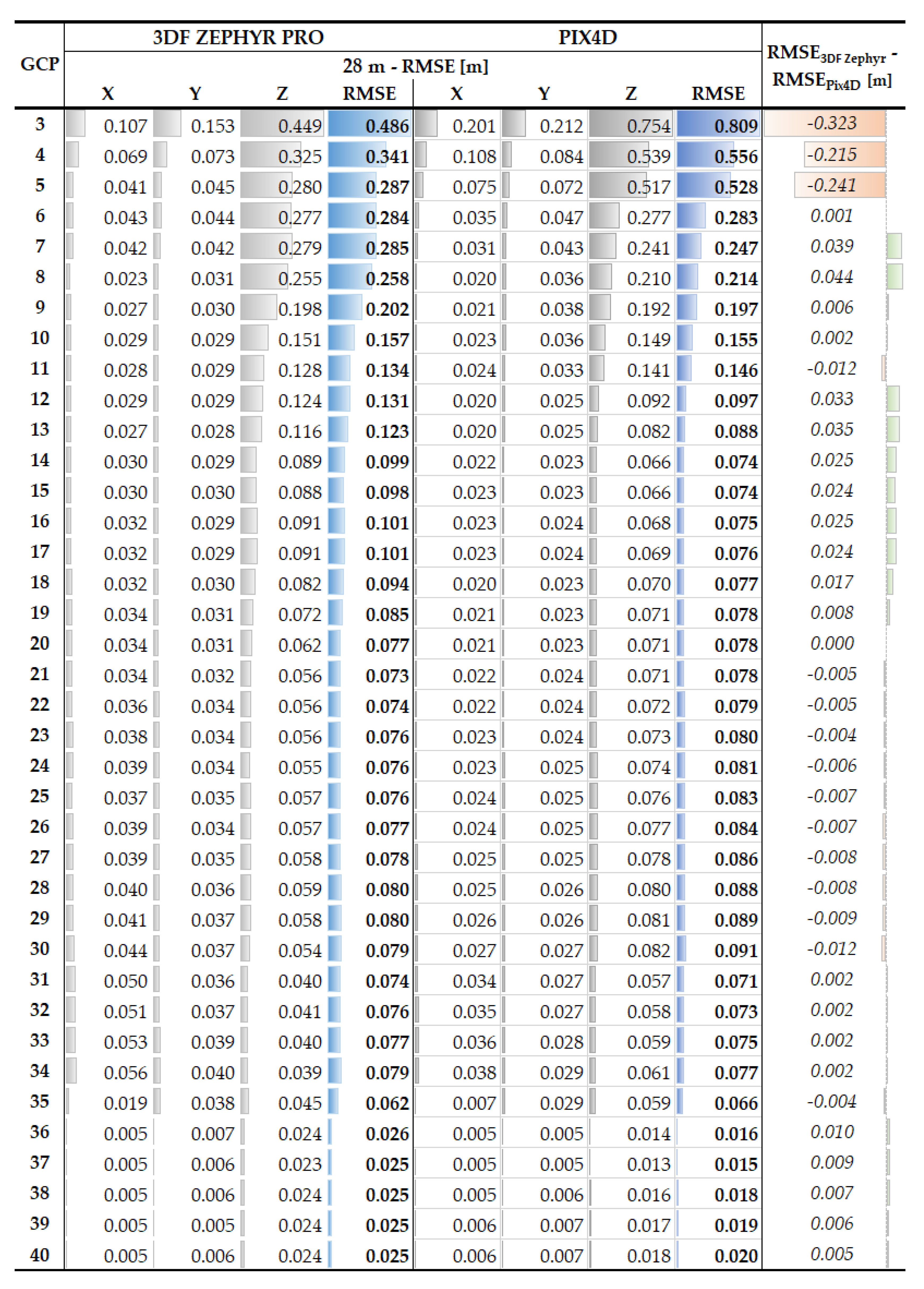
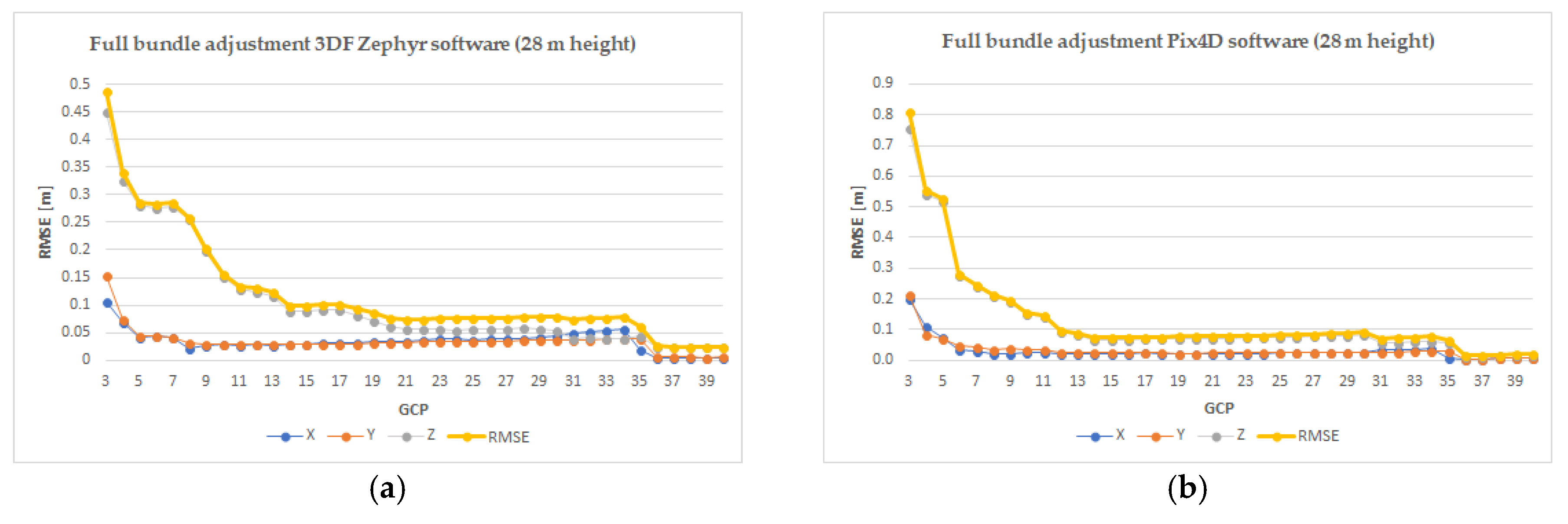
When using the Pix4D software and a full bundle adjustment process, for the minimum number of GCPs a RMSE of 81 cm was obtained, calculated for 47 CPs whereas for the maximum number, i.e., 40 GCPs, a RMSE of 2 cm was obtained, calculated for the remaining 10 CPs, although after only 5 GCPs the error decreased down to 28 cm from 53 cm (
Figure A1b,
Figure A4). The analysed results presented in
Appendix A, show that the sub-decimetre error is obtained with 12 GCPs, and the optimum number of GCPs for georeferencing the nadiral UAV images is 14, as from this point the errors varies in the range of 1 cm until 36 GCPs is reached, for which the RMSE is 1.6 cm.
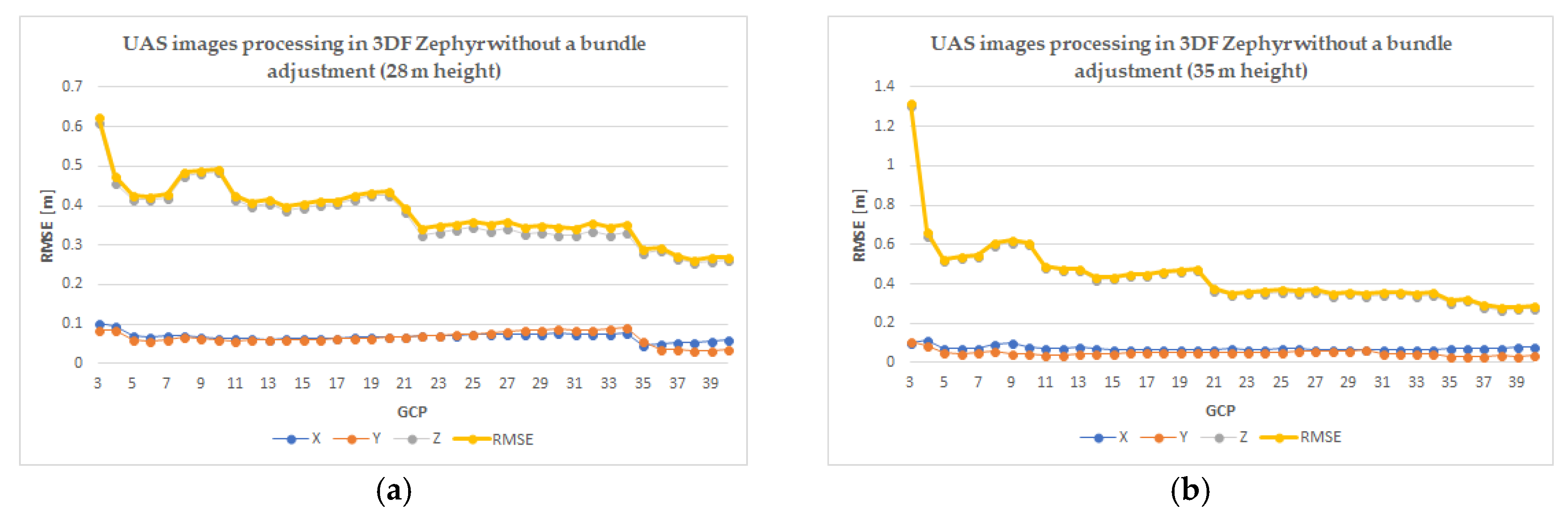
When using the 3DF Zephyr Pro software and a full bundle adjustment process, for the minimum number of GCP a RMSE of 49 cm was obtained while for the maximum number, i.e., 40 GCPs the obtained RMSE is 2.5 cm (
Figure A1a,
Figure A4). As shown by the results presented in
Appendix A, the sub-decimetre error is obtained with 14 GCPs, and the optimum number of GCPs for georeferencing the nadiral UAV images is 20, as from this point the error varies in the range of 1 cm until reaching 36 GCPs, where the RMSE is 2.6 cm.
Regarding the third test made with the 3DF Zephyr Pro software, for the minimum number of GCP a RMSE of 61.1 cm was obtained and for the maximum number, a RMSE of 27.1 cm was obtained (
Figure A3a).
4.2. Results Corresponding to 35 m Height Flight
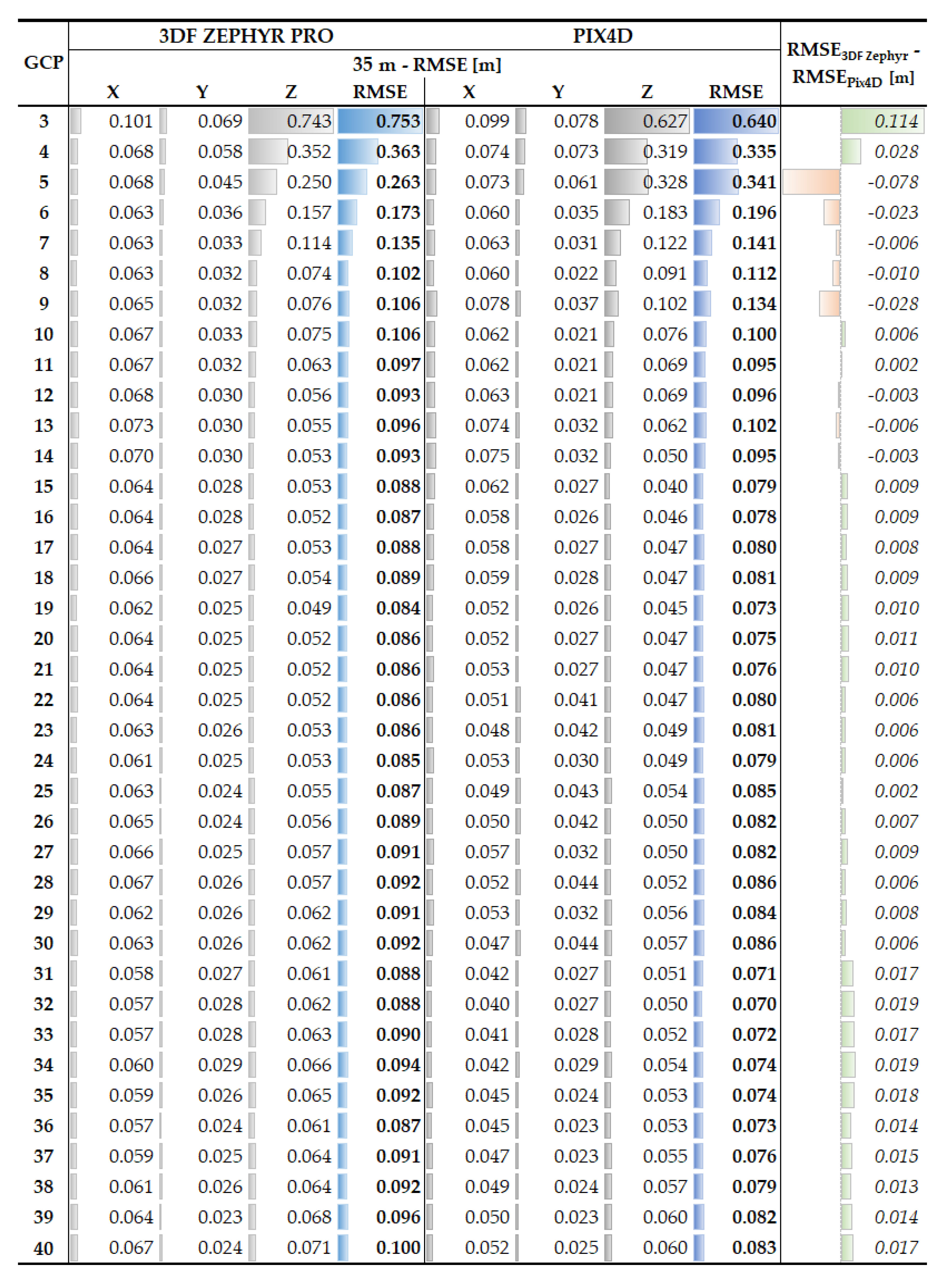
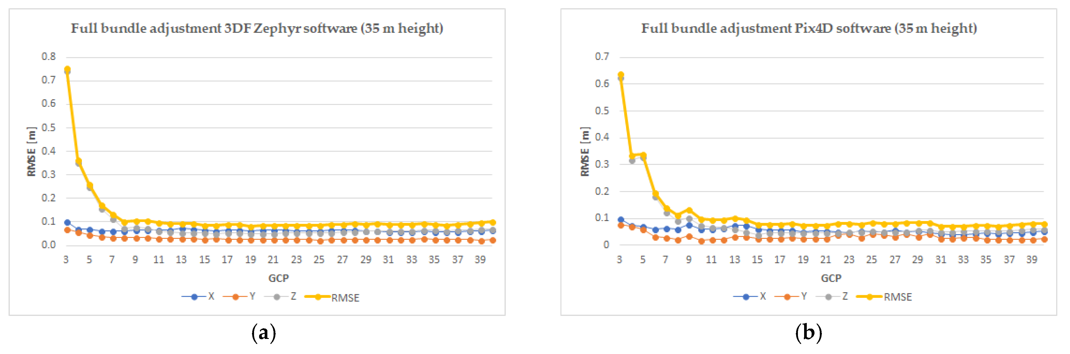
Considering
Appendix A data for Pix4D software, it can be noted that the sub-decimetre error is achieved with 14 GCPs and that 15 GCPs represents the optimum number for georeferencing the nadiral UAV images, as for the following tests the error varies within 1 cm (
Figure A2b,
Figure A5). Similarly, concerning the case of 3DF Zephyr Pro software, the optimum number of GCPs is also 15 (
Figure A2a,
Figure A5). Comparing the two software in terms of the minimum error, 7 cm corresponds to the Pix4D software when using 32 GCPs, and 8.4 cm is the minimum error for the 3DF Zephyr Pro for 19 GCPs. On the other hand, in the third case of image processing with 3DF Zephyr Pro software without performing a bundle adjustment, the minimum number of GCP RMSE of 1.32 cm was obtained, whereas the maximum number has a RMSE of 28.8 cm (
Figure A3b).
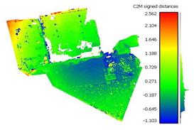
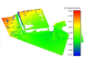
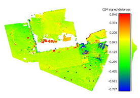
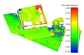
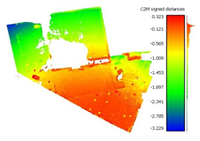
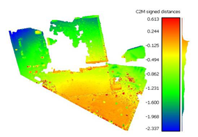
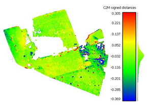
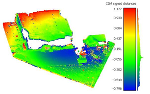
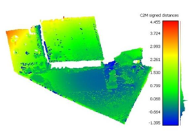
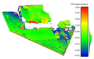
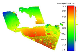
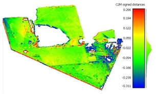
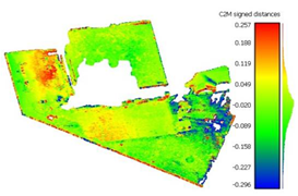
To determine the accuracy of the 3D point clouds and mesh surfaces (
Appendix B and
Appendix C), a comparison method between the point cloud and a reference mesh surface was utilized; for this case study, the mesh created based on the TLS data was considered. The comparisons were made using the “Distance-Cloud/Mesh Dist” function from the “Tools” menu implemented into CloudCompare software, being calculated as the Hausdorff distances between each point and the corresponding triangle surface. The calculated distances are summarized in
Table 1.
5. Discussion
Before image processing in Pix4D, several tests were undertaken to assure the right workflow. For both flights, 5 to 18 cameras (for 35 m and 28 m, respectively) remained uncalibrated when the settings were left as default and for improving the number of calibrated cameras without adding more control points. After various tests such as importing the GCP after the initial processing (resulted in 1 block with 5 uncalibrated cameras for 35 m) or running the project without MTP (resulted in 2 image blocks and 4 uncalibrated cameras for 28 m), changing the coordinate system for the entire project and importing the images without geolocation gave the best results: 1 image block with 1 uncalibrated camera for 35 m and 6 cameras for 28 m. On the other hand, from a time-consumption perspective, it was more efficient if the computed position of the control points remains unchanged when the project is overwritten and optimized (e.g., when computing the project from X GCP to X + 1 GCP). Each time a new project is done, it is more beneficial because in the first situation the results from the first project influence the ones from the following project and to avoid any errors it is better to process each scenario independently. For a quick overview of the processed project, the Quality Report offers various details including information about GCP, the section where two points, 49 and 97, are listed in red as if they were not taken into consideration even though when checking their properties in “rayCloud” the positions are computed. Moreover, the rayCloud offers the user the possibility of exporting the points as a shapefile or other similar formats, except for table format extensions (e.g., txt).
The differences between the RMSE obtained for each number of GCPs by processing the projects with Pix4D software and Zephyr Pro software, are very similar with a range of a few millimetres up to 3 cm, except for the first three case: using 3, 4 and 5 GCPs when the RMSE is 40% smaller in the case of 3DF Zephyr Pro software for the 28 m flight; the reason for this is unclear. Moreover, when using the 3DF Zephyr Pro software all images were orientated without making any additional steps. The RMSE is influenced by the errors encountered in some CP points, namely, 1, 49 and 97 situated on the roof edge. The optimum number of GCPs for georeferencing the UAS images when using the Pix4D software was 14 for the 28 m flight and 15 for the 35 m flight and when using the 3DF Zephyr Pro software the optimum number was 20 for the 28 m flight and 15 for the 35 m flight, with similar results being reported in [
3] but for georeferencing a Digital Surface Model derived from a 120 m flight. The number of GCPs had a very small influence on RMSEx and RMSEy starting with 6 GCPs used in the georeferencing process, as it can be seen from the graphics reported in
Figure A1,
Figure A2 and
Figure A3 and the flight altitude did not have a significant influence on RMSEz, contrary to the results reported in [
2]. Moreover, increasing the number of GCPs had a significant influence on RMSEz until a certain number was reached and it increased the accuracy of the final products as also mentioned in [
1,
2].
Very large errors were found in the area situated outside the surface covered by the GCPs (the parking lot situated on the right side of the building), being approximately 3 m when using only 3 GCPs, decreasing to a decimetre level when using the optimum number, but still being five times larger than those encountered in the GCP area.
6. Conclusions
This article presented a metric evaluation of automatically generated point clouds and mesh surfaces, based on UAS images acquired with a low-cost platform, i.e., DJI Phantom 3 Standard, using two different software with the capability of automatically orienting the images, Pix4D and 3DF Zephyr Pro. We also determined the optimum number of GCPs in order to georeference a block of nadiral UAS images, by processing the images with 3 GCPs, 4 GCPs, up to 40 GCPs, finding almost the same number for the 28 m and 35 m flight and for the two different software. We can conclude that in order to obtain high accuracy of the final products, a density of 1 GCP/200 m2 is necessary.
The results demonstrated a clear overview of the number of GCPs needed for the indirect georeferencing process with minimum influence on the final results.


