Abstract
The mechanism of propulsion in swimming has been widely researched in recent years, but not completely clarified. While it is obvious that the movement of arms provides most of the thrust, it is unclear how each phase of the stroke translates into body acceleration. Investigation is carried out mainly by video analysis or using Inertial Measurement Units (IMUs) which do not measure forces. In this paper, we present a wearable data acquisition system for swimmers. The system is composed of two instrumented paddles, measuring the pressure difference between palm and back of the hands, and an IMU. The paddles provide information about the forces that cause propulsion, while the IMU measures the effects of these forces. Data are acquired by a microcontroller unit placed in waterproof case at the athlete’s waist, and transferred to PC via a Bluetooth link. Early experimental data are presented.
1. Introduction
Swimming is a highly technical sport. Since water is about 800 times denser than air, drag, lift and buoyancy are, all else being equal, much more intense in air than in water. A correct swimming technique is essential in order to maximise thrust and reduce drag, therefore increasing the swimmer’s velocity.
Swimming technique has been widely investigated using videos and other visualization tools since in 1971 Counsilman gave his first contribution [1]. More recently, other technology based approaches have been adopted: wind tunnel tests (Takagi, 1999 [2,3]), particle image velocimetry (PIV) in a flume (Matsuuchi et al., 2009 [4]), CFD simulation (for instance, Cohen et al., 2015 [5]).
While scientifically sound, these approaches are no help in the daily work of coaches and athletes, and cannot be used to analyse the technique of individual swimmers.
Availability of light, inexpensive inertial sensors (Inertial Measurement Units, IMU in the following, composed of a triaxial accelerometer and a triaxial gyroscope) has led to a series of studies (see Mooney et al., 2016, for a systematic review [6]) centered on technical aspects and performance analysis.
An IMU is certainly an ideal, unobtrusive sensor for kinematic analysis, but can only deliver indirect information about propulsion, which is a dynamic process.
Unlike a runner, a swimmer has no contact with a solid floor. Propulsion is the horizontal resultant of the pressure field he creates around his body, essentially with the motion of his arms and legs. Hands in particular play a fundamental role. In 2002 Takagi et al., have pioneered the use of pressure sensors on the hands of the swimmer to evaluate propulsion [7]. While, in 2010, Bottoni et al. have presented a wearable system where the pressure signal is acquired by means of special plastic paddles with a double membrane [8]. While very effective in measuring thrust, though, the system provided no information about the acceleration that thrust creates.
In this paper, we present an evolution of this system that combines dynamic measurement coming from the paddles with kinematic measurement obtained by an IMU placed at the hips of the swimmer.
The system, called KZ+, provides complete information about propulsion created by the upper limbs of the athlete and its effects on the athlete’s motion.
2. Hardware Description
The KZ+ system is composed of two instrumented mini paddles that the athlete wears on his hands (Figure 1a) and a wearable DAQ (Digital Acquisition System) unit placed on the back of the swimmer in a waterproof enclosure (Figure 2b) and equipped with the IMU. The paddles and DAQ unit are connected via small silicon tubes and the tubes are secured to the arms and shoulders of the swimmer by rubber bands.
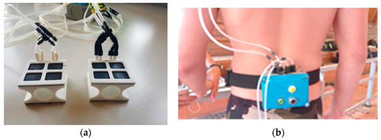
Figure 1.
(a) Mini paddles; (b) DAQ unit.
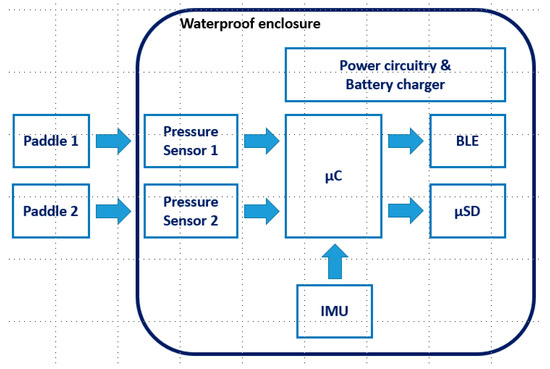
Figure 2.
Block scheme of the system.
Moreover, the paddles present a size and a shape that do not affect the swimmer’s movements neither his feel for the water.
A block diagram of the system is shown in Figure 2.
Each paddle has a membrane on the palm and one on the back of the hand. Dynamic pressure of the water applies a force on each membrane, compressing the air included in two small waterproof chambers, which are connected to the pressure sensors in the DAQ unit via the silicon tubes.
The paddles are connected to a couple of integrated differential pressure sensors (Freescale Semiconductor—MPXV4006DP). These sensors are piezo resistive transducers that provide an accurate analog output signal proportional to the difference of pressure between their two inlets. In particular, it presents a 2.5% maximum error over +10 °C to +60 °C. The output of these pressure sensors is connected to the ADC (Analog to Digital Converter) inputs of the microcontroller (10 bit resolution) and acquired at a sample rate of 20 Hz or 50 Hz selectable by the user.
The differential pressure sensors measure the difference in pressure between palm and back; since hydrostatic pressure has the same value on both sides of the hand, it has no influence on the measurement.
The electronic system is based on the Arduino 101 board. This board mounts an Intel Curie® processor: it is a SOC (System on Chip) composed of an Intel Quark X86 ISA-compatible 32 bit processor, an IMU (Bosch Sensortec BMI160) and a BLE (Bluetooth Low Energy—Nordic Semiconductor nRF51822). The processor architecture is a 32 bit ARC (Argonaut RISC Core) with a clock of 32 MHz, a SRAM sized 24 kB and 196 kB Flash Memory [9].
The IMU is a small, low power, low noise 16-bit device that can measure an acceleration ranging from ±2 g and ±16 g selectable by the user with a resolution that ranges from 16384LSB/g (with an amax of ±2 g) and 2048LSB/g (amax of ±16/g). The measured angular speed can range from ±125°/s to ±2000°/s, again user selectable with a sensitivity that ranges from 262.4 LSB/°/s (@ Gmax = ±125°/s) to 16.4 LSB/°/s (@ Gmax = ±2000°/s). Finally, the BLE circuit (nRF51822) is a Bluetooth® low energy for 2.4 GHz ultra low-power wireless applications. A proper shield board (shown in Figure 3) has been designed to host the pressure sensors as well as a SD (Secure Digital) memory circuit and the battery charger circuitry.
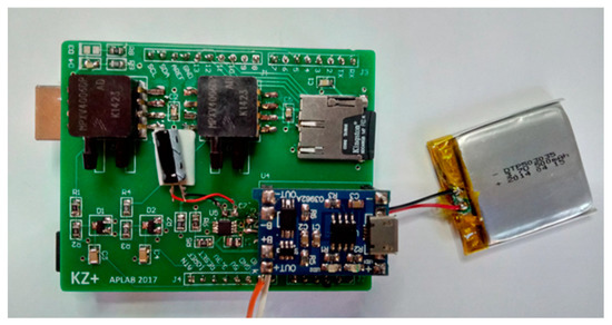
Figure 3.
Purpose made shield for sensors, SD card and battery recharge circuitry.
The system is powered by a 3.7 V LiPo battery. The enclosure (IP 68—suitable for continuous immersion) has neutral buoyancy and the whole system does not interfere with the action of the athlete, who can swim freely (Figure 4). A proper software controls the selection of the acquisition rate (20 or 50 Hz), the start/stop of the acquisition and the data download operation.
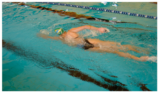
Figure 4.
The swimmer is not constrained in her motion by the system.
3. Results
A written informed consent was obtained from all the participants after familiarization and explanation of the benefit and risks involved in the procedures adopted. The study was approved by the Ethical Committee of the School of Sports and Exercise Science—University of Rome “Tor Vergata”—Faculty of Medicine and Surgery. Moreover, all the tests were carried out in accordance with the Declaration of Helsinki.
In the following charts, Lx indicates the differential pressure measured on the left hand, Rx the same on the right hand, while accx and accy are the accelerations along the three axes as shown in Figure 5. It is worth noting that all three axes will rotate with respect to a fixed reference frame during the motion of the swimmer. Some preliminary test in the three different swimming strokes will be presented.
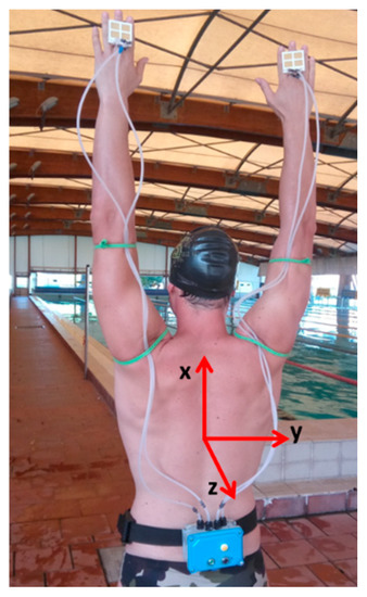
Figure 5.
Reference frame of the system.
Figure 6 shows several freestyle strokes cycles. The first set of cycles is performed at slow pace, the second, after a short pause, at race pace. The upper chart shows the pressure signals while the lower one the acceleration along the X and Y axis.
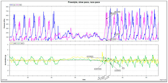
Figure 6.
Freestyle, slow pace, race pace.
The stroke cycle shows the typical two-peaked pattern. Race pace cycles have a higher frequency and a higher intensity. Y-axis acceleration shows a deeper, sharper curve in the race pace cycle, related to a deeper roll movement. Peaks in forward acceleration fall halfway through the underwater phase of the stroke.
Figure 7 shows steady breaststroke cycles: you can note that the forward acceleration and the pressure peaks are more intense than in freestyle (see clipping on the left curve). Acceleration peaks happen just before pressure peaks. An intermediate acceleration peak caused by kicks is visible between two strokes.
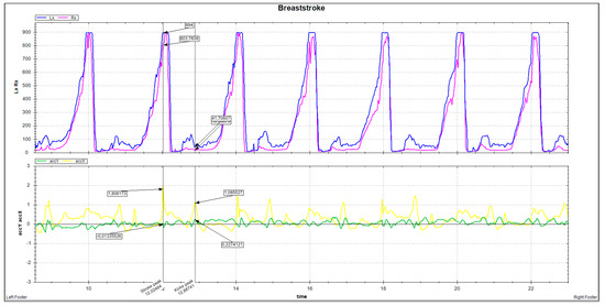
Figure 7.
Steady breaststroke cycles.
Highlights in Figure 8 (Butterfly): double peak hand profile; propulsion peak over 900 (with clipping on left paddle); very high acceleration peak (about 2 g), synchronized to propulsion peak; acceleration transfer between X and Z axes. Intermediate acceleration peaks caused by kicks.
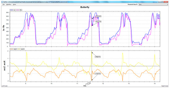
Figure 8.
Butterfly cycles.
4. Conclusions
A wearable, unobtrusive multichannel data acquisition system for swimmers has been presented. KZ+ combines dynamic measurements obtained by differential pressure sensors placed on the hands of the swimmer with kinematic measurements obtained by an IMU placed on the back of the swimmer. Thanks to its combination of sensors, the system provides researchers and coaches with information about the propulsion generated by the swimmer and its effect on the motion of the athlete. Easy to carry and to use, KZ+ is designed not only as a research tool, but as an instrument for training. Early test showed that the system can provide useful information about the main parameters that define the technique of a swimmer.
Acknowledgments
The authors wish to thank the Italian Olympic Committee (CONI) for the use of its facilities at “Giulio Onesti” training center in Rome.
Conflicts of Interest
The authors declare no conflict of interest. The funding sponsors had no role in the design of the study; in the collection, analyses, or interpretation of data; in the writing of the manuscript, and in the decision to publish the results.
References
- Counsilman, J.E. The Application of Bernoulli’s Principle to Human Propulsion in Water; Swimming, I., Lewillie, L., Clarys, J.P., Eds.; Universite´ Libre de Bruxelles: Brussels, Belgium, 1971; pp. 59–71. [Google Scholar]
- Takagi, H.; Shimizu, Y.; Kodan, N. A hydrodynamic study of active drag in swimming. JSME Int. J. Ser. B Fluids Therm. Eng. 1999, 42, 171–177. [Google Scholar] [CrossRef]
- Takagi, H.; Wilson, B. Calculating hydrodynamic force by using pressure differences in swimming. Biomech. Med. Swim. 2015, 8, 101–106. [Google Scholar]
- Matsuuchi, K.; Nomura, J.; Sakakibara, T.; Shintani, H.; Ungerechts, B.E. Unsteady flow field around a human hand and propulsive force in swimming. J. Biomech. 2009, 42, 42–47. [Google Scholar] [CrossRef] [PubMed]
- Cohen, R.; Cleary, P.; Mason, B.; Pease, D. The Role of the Hand during Freestyle Swimming. J. Biomech. Eng. 2015, 137. [Google Scholar] [CrossRef] [PubMed]
- Mooney, R.; Corley, G.; Godfrey, A.; Quinlan, L.R.; ÓLaighin, G. Inertial Sensor Technology for Elite Swimming Performance Analysis: A Systematic Review. Sensors 2016, 16, 18. [Google Scholar] [CrossRef] [PubMed]
- Takagi, H.; Sanders, R. Measurement of propulsion by the hand during competitive swimming. In The Engineering of Sport 4; Wiley-Blackwell: Oxford, UK, 2002; pp. 631–637. [Google Scholar]
- Bottoni, A.; Lanotte, N.; Bifaretti, S.; Boatto, P.; Gatta, G.; Bonifazi, M. Direct measurement of stroke propulsion in real swimming by means of a non invasive gauge. In Proceedings of the XI International Symposium for Biomechanics in Swimming, Oslo, Norway, 16–19 June 2010. [Google Scholar]
- Intel® Curie™ Module, Document rev. 1.3; Datasheet, March 2017. Available online: https://www.intel.com/content/dam/support/us/en/documents/boardsandkits/curie/intel-curie-module-datasheet.pdf (accessed on 3 February 2018).
Publisher’s Note: MDPI stays neutral with regard to jurisdictional claims in published maps and institutional affiliations. |
© 2018 by the authors. Licensee MDPI, Basel, Switzerland. This article is an open access article distributed under the terms and conditions of the Creative Commons Attribution (CC BY) license (https://creativecommons.org/licenses/by/4.0/).