Evaluation of a Differentiation Scheme for Estimating Angular Acceleration from Angular Velocity †

School of Mechanical and Materials Engineering, Washington State University, Pullman, WA 99163, USA
*
Author to whom correspondence should be addressed.
†
Presented at the 12th Conference of the International Sports Engineering Association, Brisbane, Queensland, Australia, 26–29 March 2018.
Proceedings 2018, 2(6), 271; https://doi.org/10.3390/proceedings2060271
Published: 23 February 2018
(This article belongs to the Proceedings of The 12th Conference of the International Sports Engineering Association)
Abstract
:Headform impact testing is commonly used in the evaluation of helmets and head gear, head impact sensors and in sports related accident reconstruction. While linear acceleration of the headform center of mass can be measured using three linear accelerometers, the preferred method for measuring rotational acceleration of the headform requires six or more additional accelerometers. Some measurement systems use gyroscopes to directly measure headform angular velocity and obtain angular acceleration through differentiation. This approach simplifies instrumentation of the headform and reduces costs, but at the expense of accuracy. Error introduced through differentiation of angular velocity data can be prohibitively large for some sports applications, particularly in the consideration of un-helmeted headform impacts. This work considers the application of a new, optimization-based differentiation technique to improve the fidelity of headform angular acceleration estimates based on gyroscope measures of headform angular velocity. A Hybrid III headform instrumented with three gyroscopes and nine linear accelerometers was subject to drop impacts, as well as being impacted with soccer balls and softballs projected over a range of velocities. Measures of resulting headform angular acceleration were obtained from the gyroscope data using five-point stencil differentiation and the new optimization based algorithm. These results were compared to the nine accelerometer array measurements of angular acceleration across impact scenarios.
1. Introduction
Accurate measurement of linear and angular acceleration of rigid bodies has found an important application in head impact research. Head impact research is primarily conducted using instrumented headforms, most commonly the Hybrid III and NOCSAE. Accelerations and associated metrics measured during headform impact testing are compared to head injury thresholds to determine the acceptability of helmet and headgear performance in mitigating the risk of injury for a given impact [1,2,3]. While many test standards utilize the same accelerations or other metrics to evaluate performance of player protective equipment, several methods may be used to obtain headform kinematics during an impact.
Each technique to describe the 6 degrees of freedom of a headform, consists of an array of sensors, notably the 3-2-2-2 array and 3aω. The 3-2-2-2 is an array of 9 linear accelerometers configured with 3 accelerometers located at the center of gravity (CG) of the headform and 3 biaxial pairs located a known distance from the CG (Figure 1) Padgaonkar [4]. The 3-2-2-2′s ability to measure linear and rotational acceleration directly make it useful because helmet certification and injury thresholds are commonly based on these accelerations. The 3-2-2-2 has been widely used and praised for its robustness, reliability and computational stability, and deemed by some as the preferred technique [5,6,7]. The 3aω is another array consisting of 3 accelerometers located at the CG but differs from the 3-2-2-2 in the use of 3 gyroscopic angular rate sensors [8,9]. The 3aω has distinct benefits over the 3-2-2-2 in channel count, consisting of 6 sensors instead of 9. This simplifies the array, makes it more compact and simplifies the data acquisition system. The angular rate sensors are also better at capturing longer duration impacts and are insensitive to mounting location [7]. Angular accelerations from the 3aω are calculated by differentiating the velocities obtained from the gyroscopes, which can amplify noise and negatively affect the accuracy of the angular accelerations [7].
Several techniques have been developed to improve the accuracy of angular accelerations from the 3aω’s angular velocity measurements. Various methods have been implemented to optimize filtering to obtain a “true differentiation” [7]. Different numerical differentiation methods are available as well, and a comparison of some examples are outlined by Walker [10]. The total-variation Regularization (TV) method of differentiation developed by Rick Chartrand may improve accuracy of angular acceleration [11]. The TV method has many promising qualities for this application, including the acceptability of discontinuities, the implementation of a lagged diffusivity algorithm with proven convergence properties and regularization allowing it to capture more features of the data. The purpose of this study was to determine if the TV method of differentiation can improve the 3aω’s ability to measure angular acceleration and thereby better realize the 3aω’s advantages.
2. Materials and Methods
2.1. Data Collection
Headform impact kinematics were obtained from a Hybrid III headform and neck assembly instrumented with nine single-axis linear accelerometers (7264H-1KTZH-360, Meggitt Sensing Systems, Irvine, CA, USA) oriented orthogonally following a 3-2-2-2 arrangement (NAP), and three orthogonally mounted angular rate sensors (ARS-PRO-8K, Diversified Technical Systems, Seal Beach, CA, USA). Data from both sensor types were collected at 50 kHz.
Linear accelerations and angular velocities were measured when the headform was both impacted by projected sports balls and dropped onto an MEP pad [12]. No helmets or headgear were used in the impacts and all contact was with the bare headform. For sports ball impacts, a solid (softball) and inflated (soccer ball) sports ball were projected at 20 m/s and 27 m/s, respectively, by a pneumatic cannon. For each impact, high speed video recorded at 3000 fps was reviewed to confirm a consistent impact location at the forehead of the headform, though substantive deformation of the soccer ball resulted in a larger contact area (Figure 2). For drop impacts, the headform and neck assembly was mounted on a NOCSAE-compliant drop carriage, using twin-wire guides and dropped from a height of 1.07 ± 0.003 m (Figure 3). Linear acceleration and angular velocity data were recorded for twelve impacts with each ball and from drops.
2.2. Data Analysis
Linear acceleration was filtered using a fourth-order, low-pass Butterworth filter with a cut-off frequency of 1650 Hz. Angular velocity was filtered using a fourth-order, low-pass Butterworth filter, but over a range of frequencies as detailed below. Angular accelerations were calculated using three methods. First, angular acceleration was obtained from the filtered linear acceleration signals as described elsewhere [4]. Second, a five-point stencil method was used to calculate angular acceleration from the filtered angular velocity data [13,14]. Finally, angular acceleration was calculated from the angular velocity data using an iterative method of total variation (TV) regulation [11].
The TV regulation method is an optimization-based approach to numerical differentiation which minimizes the sum of a regularization penalty term and an anti-differentiation term. The regularization term increases with greater irregularity of the differentiated data, while the anti-differentiation term increases with the difference between the undifferentiated signal and the integral of the differentiated data. A scalar, α, is used to define the relative weight of these parameters within the minimization operation. The method has been shown to perform well in cases where denoising of data is not possible, but does require the arbitrary selection of α, for which there is no physically meaningful value.
The relative performance of the five-point stencil and TV regulation methods were evaluated for angular velocity filter cut-off frequencies ranging from 1 kHz to 2 kHz. The minimum cut-off frequency was selected as a lower-bound for the un-helmeted headform, while the data-sheet specified frequency response limit of the angular rate sensors was selected for the maximum cut-off frequency. For each impact, performance of the five-point stencil and TV regulation methods was assessed using the mean normalized error (MNE), given by:
where is the maximum angular acceleration observed for the ith impact, is the maximum angular acceleration obtained by differentiation of angular velocity data from the same impact, and n the total number of impacts. For each cut-off frequency examined, the “optimal” α across all impacts, defined as the value of α resulting in the lowest MNE, was identified and used in the analysis. In this way, the maximal advantage through the TV regulation method was characterized.
3. Results
Lower cut-off frequencies for processing rotational velocity resulted in smoother angular acceleration traces from both differentiation techniques and under-estimation of peak angular accelerations for short duration contacts (Softball) compared to measures obtained from the NAP system. Increasing the cut-off frequency resulted in greater noise and over-estimation of peak angular acceleration for longer duration contacts (Soccer ball, Drop; Figure 4).
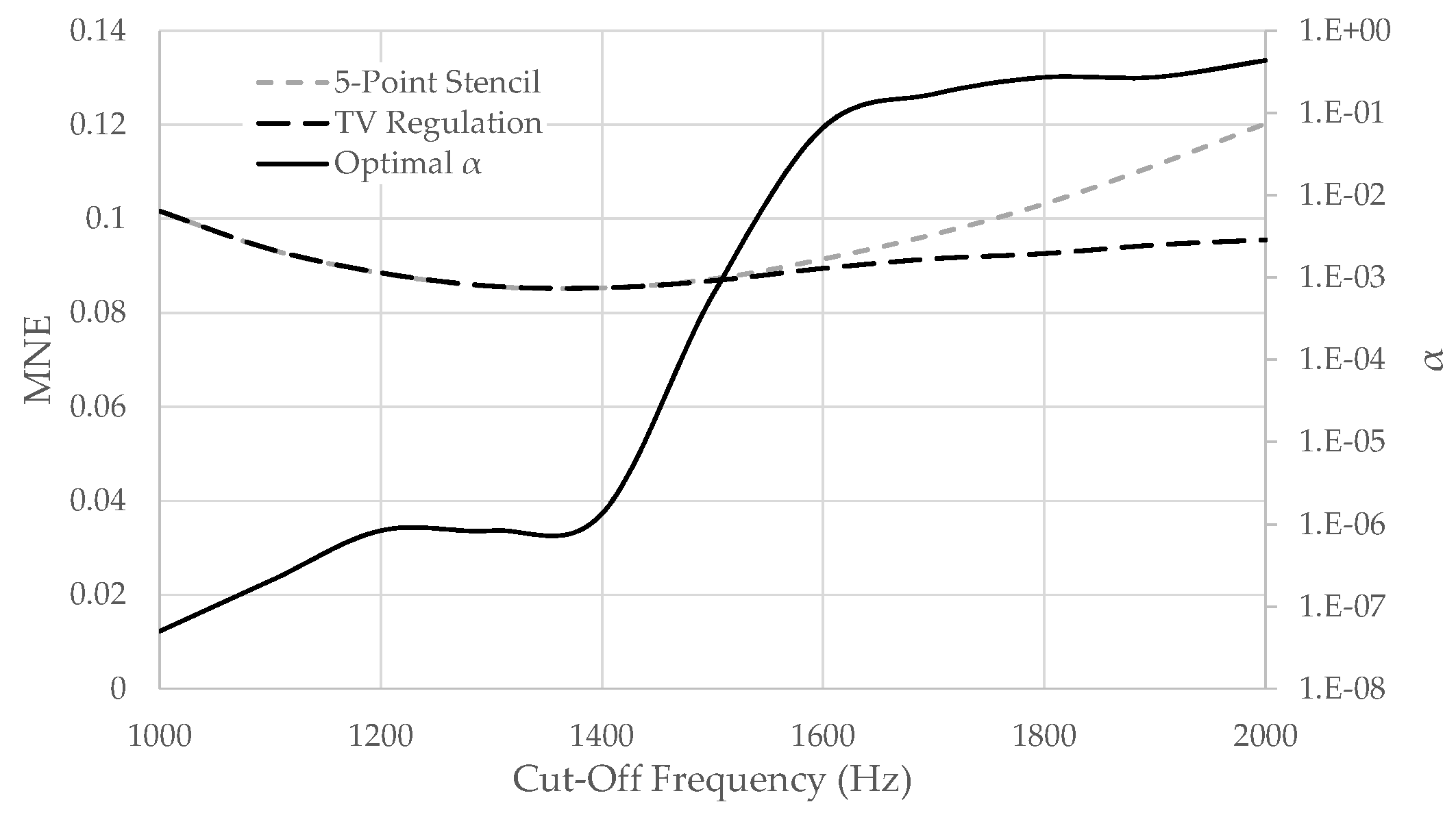
Performance of the five-point stencil technique and the TV regulation method were indistinguishable for cut-off frequencies below approximately 1500 Hz, and optimum performance, when assessed by MNE, was achieved by a cut-off frequency near 1300 Hz for both differentiation techniques. For cut-off frequencies above that 1500 HZ performance of the two methods diverged, with performance of the TV regulation method decreasing more slowly than the five-point stencil (Figure 5).
4. Discussion
This study evaluated the five-point stencil and TV regulation methods for obtaining measures of angular acceleration from angular velocity data by comparing their output to measures of angular acceleration obtained from a 3-2-2-2 linear accelerometer array. Each method was evaluated for softball impacts, soccer ball impacts and drop tests with a bare headform.
Comparison of the differentiation methods indicated that, should an optimal α value be used, the TV regulation method performed as well as or better than the five-point stencil methods across all cut-off frequencies examined. This result describes the maximal benefit afforded by the use of the TV regulation method across a particular set of impacts, and future work will be required to determine if the improvement persists when values of α are selected without a priori knowledge of the true signal. Furthermore, analysis techniques like k-fold cross-validation will be needed to assess the robustness of the approach in future investigations. Results of the current study suggest that, for MNE, if the most appropriate cut-off frequency or α value are not known with confidence prior to analysis, filtering angular velocity data more aggressively, rather than less, will produce the best performance on average.
These results are likely most useful for novel investigations of un-helmeted head impact, as most test standards utilizing headforms for the purpose of measuring angular head accelerations do so to evaluate the performance of helmets or headgear [15,16,17]. Nevertheless, these results may provide benefit for researchers using un-helmeted headforms and those conducting cadaver studies in fields ranging from sports science to automotive safety.
5. Conclusions
The TV regulation method of differentiation may offer improved performance compared to the five-point stencil differentiation technique in cases where frequency content of the angular acceleration signal is believed to exceed 1500 Hz and the most appropriate cut-off frequency is unknown.
Conflicts of Interest
The authors declare no conflict of interest.
References
- Gadd, C.W. Use of a Weighted-Impulse Criterion for Estimating Injury Hazards. In Proceedings of the Tenth Stapp Car Crash Conference, Los Angeles, CA, USA, 8–9 November 1966. [Google Scholar]
- Newman, J.A. A generalized acceleration model for brain injury threshold (GAMBIT). In Proceedings of the International IRCOBI Conference on the Biomechanics of Impacts, Zurich, Switzerland, 2–4 September 1986. [Google Scholar]
- Newman, J.A.; Shewchenko, N.; Welbourne, E. A proposed new biomechanical head injury assessment function—The maximum power index. Stapp Car Crash J. 2000, 44, 215–247. [Google Scholar] [PubMed]
- Padgaonkar, A.J.; Krieger, K.W.; King, A.I. Measurement of angular acceleration of a rigid body using linear accelerometers. J. Appl. Mech. 1975, 42, 552–556. [Google Scholar] [CrossRef]
- Kang, Y.-S.; Moorhouse, K.; Bolte, J.H. Measurement of six degrees of freedom head kinematics in impact conditions employing six accelerometers and three angular rate sensors (6aω configuration). J. Biomech. Eng. 2011, 133, 111007. [Google Scholar] [CrossRef] [PubMed]
- Takhounts, E.; Eppinger, R.; Tannous, R.; Campbell, J.Q.; Power, E.; Shook, L.; Hasija, V. Analysis of 3D Rigid Body Motion Using the Nine Accelerometer Array System. Inj. Biomech. Res. 2003, 59–76. [Google Scholar]
- Bussone, W.R.; Bove, R.T.; Thomas, R.; Richards, D.; Prange, M.T. Six-Degree-of-Freedom Accelerations: Linear Arrays Compared with Angular Rate Sensors; SAE Technical Papers; No. 2010-01-1017; SAE International: Hong Kong, China, 2010. [Google Scholar]
- Laughlin, D.R. A Magnetohydrodynamic Angular Motion Sensor for Anthropomorphic Test Device Instrumentation; SAE Technical Papers; No. 892428; SAE International: Hong Kong, China, 1989. [Google Scholar]
- Martin, P.G.; Crandall, J.R.; Pilkey, W.D.; Chou, C.C.; Fileta, B.B. Measurement Techniques for Angular Velocity and Acceleration in an Impact Environment; SAE Technical Papers; No. 970575; SAE International: Hong Kong, China, 1997. [Google Scholar]
- Walker, J.A. Estimating velocities and accelerations of animal locomotion: A simulation experiment comparing numerical differentiation algorithms. J. Exp. Biol. 1998, 201, 981–995. [Google Scholar] [CrossRef]
- Chartrand, R. Numerical differentiation of noisy nonsmooth data. ISRN Appl Math. 2011, 2011. [Google Scholar] [CrossRef]
- National Operating Committee on Standards for Athletic Equipment (NOCSAE). Standard Test Method and Equipment Used in Evaluating the Performance Characteristics of Headgear/Equipment NOCSAE Doc ND 001-13m15c; NOCSAE: Overland Park, KN, USA, 2013; pp. 1–11. [Google Scholar]
- Kuo, C.; Wu, L.C.; Hammoor, B.T.; Luck, J.F.; Cutcliffe, H.C.; Lynall, R.C.; Kait, J.R.; Campbell, K.R.; Mihalik, J.P.; Bass, C.R.; et al. Effect of the mandible on mouthguard measurements of head kinematics. J. Biomech. 2016, 49, 1–9. [Google Scholar] [CrossRef] [PubMed]
- Wu, L.C.; Laksari, K.; Kuo, C.; Luck, J.F.; Kleiven, S.; Dale Bass, C.R.; Camarillo, D.B. Bandwidth and sample rate requirements for wearable head impact sensors. J. Biomech. 2016, 49, 2918–2924. [Google Scholar] [CrossRef] [PubMed]
- National Operating Committee on Standards for Athletic Equipment (NOCSAE). Standard Pneumatic Ram Test Method and Equipment Used in Evaluating the Performance Characteristics of Protective Headgear and Face Guards; NOCSAE: Overland Park, KN, USA, 2015; pp. 1–9. [Google Scholar]
- FIM. FIM Racing Homologation Programme for Helmets; FIM: Mies, Switzerland, 2017. [Google Scholar]
- Willinger, R.; Halldin, P.; Bogerd, C.P.; Deck, C.; Fahlstedt, M. Final Report of Working Group 3: Impact Engineering (COST Action TU1101/HOPE), Brussels, Belgium. 2015. Available online: http://publications.tno.nl/publication/34618465/RwBmO5 (accessed on 1 December 2017).
Figure 1.
Schematic showing relative arrangement of (a) 3-2-2-2 and (b) 3aω sensor arrays relative to the headform center of gravity.
Figure 1.
Schematic showing relative arrangement of (a) 3-2-2-2 and (b) 3aω sensor arrays relative to the headform center of gravity.
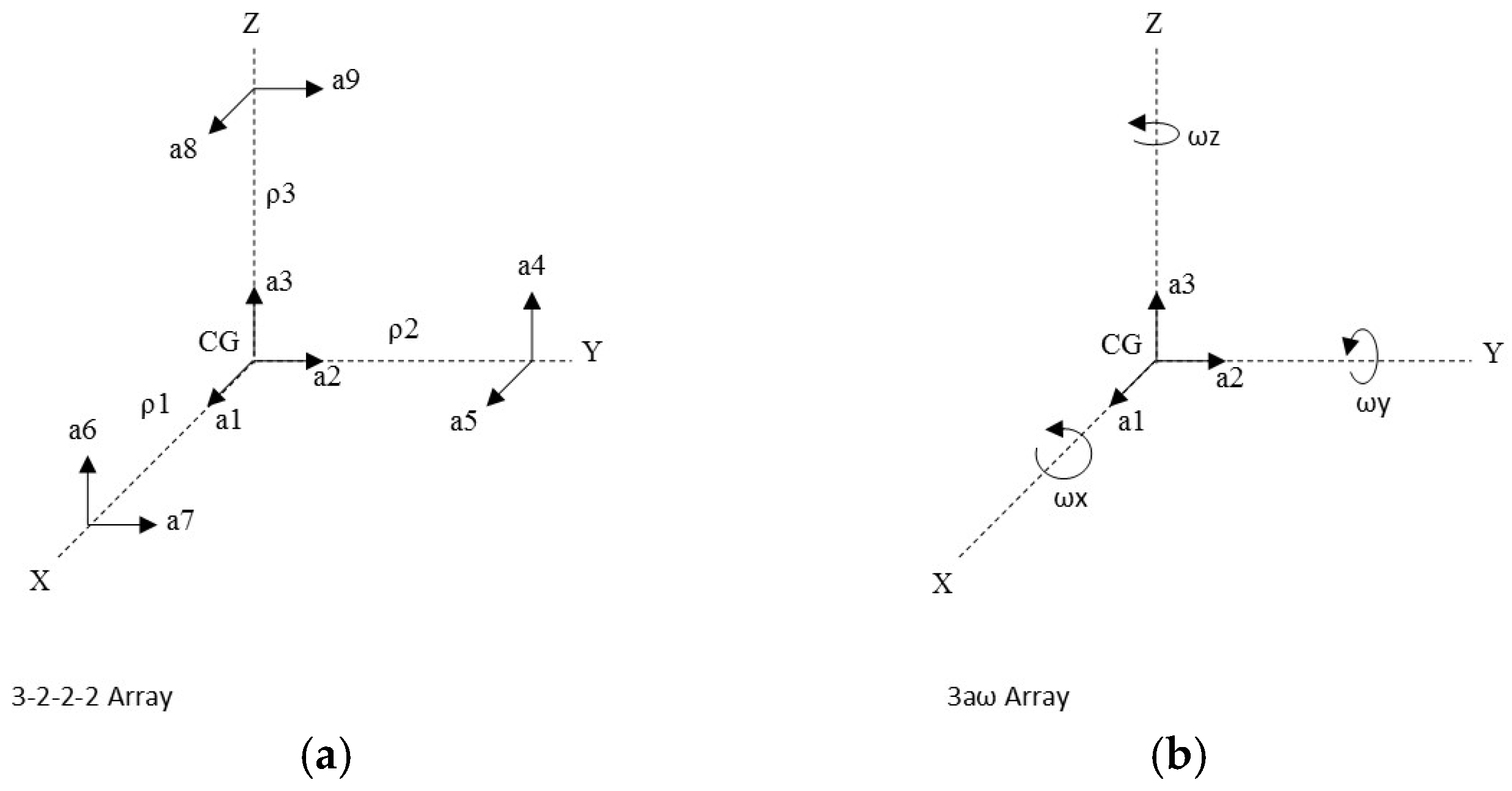
Figure 2.
Estimated initial contact (left), maximal ball deformation (middle) and end of contact (right), for softball (top) and soccer ball (bottom) impacts.
Figure 2.
Estimated initial contact (left), maximal ball deformation (middle) and end of contact (right), for softball (top) and soccer ball (bottom) impacts.
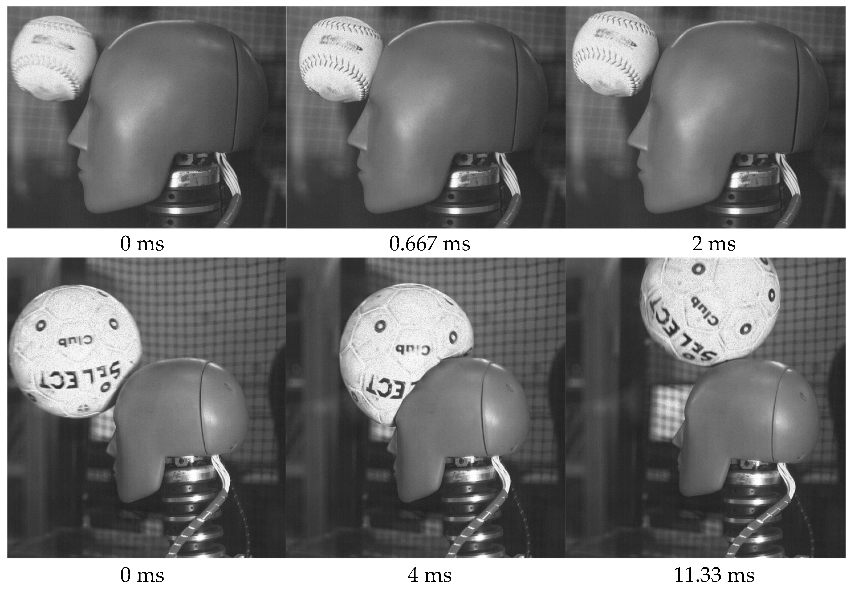
Figure 3.
Estimated initial contact (left), end of contact (middle) and maximal neck extension (right) for drop impacts.
Figure 3.
Estimated initial contact (left), end of contact (middle) and maximal neck extension (right) for drop impacts.
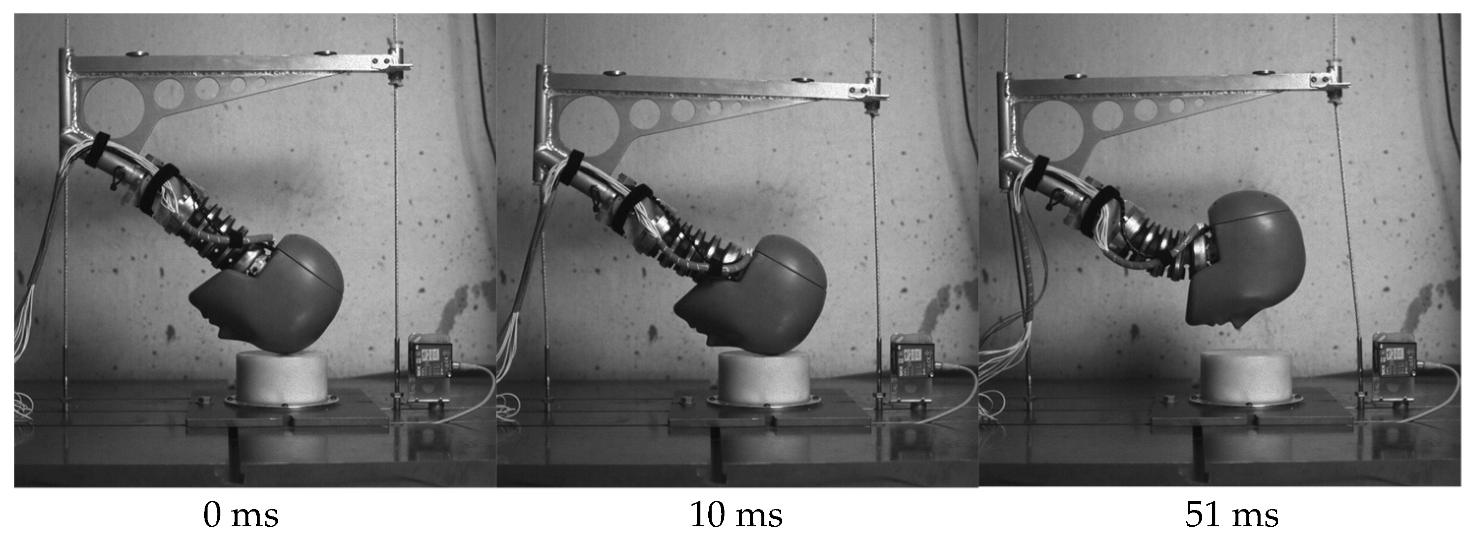
Figure 4.
Angular acceleration as a function of time for rotational velocity data filtered at 1 kHz (left) and 2 kHz (right). Data from Softball (top), soccer ball (middle) and drop (bottom) impacts are presented.
Figure 4.
Angular acceleration as a function of time for rotational velocity data filtered at 1 kHz (left) and 2 kHz (right). Data from Softball (top), soccer ball (middle) and drop (bottom) impacts are presented.
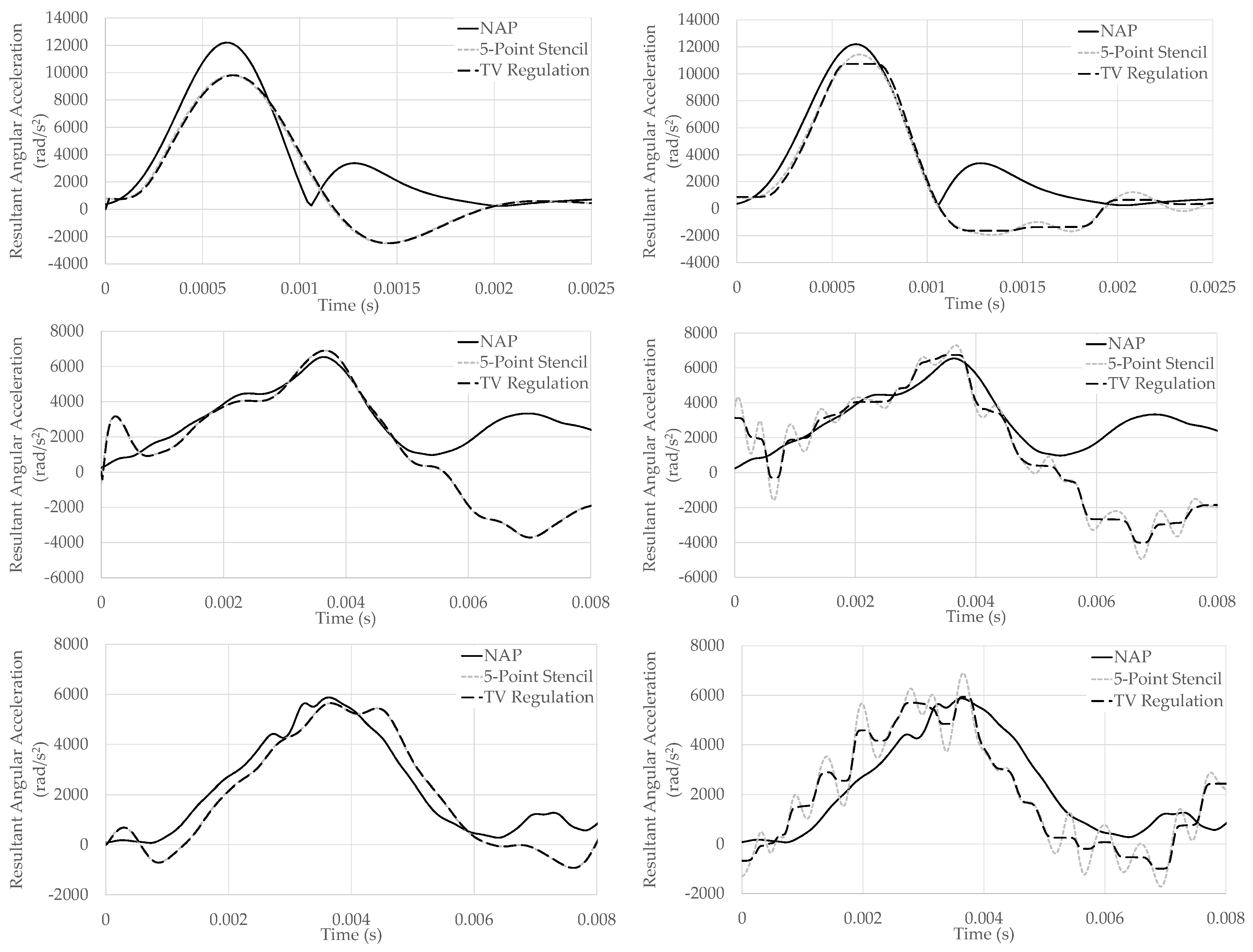
Figure 5.
Mean normalized error across all impacts for both differentiation methods as a function of cut-off frequency used to filter rotational velocity data. Also shown is the optimal α value at each cut-off frequency.
Figure 5.
Mean normalized error across all impacts for both differentiation methods as a function of cut-off frequency used to filter rotational velocity data. Also shown is the optimal α value at each cut-off frequency.
Publisher’s Note: MDPI stays neutral with regard to jurisdictional claims in published maps and institutional affiliations. |
© 2018 by the authors. Licensee MDPI, Basel, Switzerland. This article is an open access article distributed under the terms and conditions of the Creative Commons Attribution (CC BY) license (https://creativecommons.org/licenses/by/4.0/).
Share and Cite
MDPI and ACS Style
Nevins, D.; Petersen, P.; Smith, L. Evaluation of a Differentiation Scheme for Estimating Angular Acceleration from Angular Velocity. Proceedings 2018, 2, 271. https://doi.org/10.3390/proceedings2060271
AMA Style
Nevins D, Petersen P, Smith L. Evaluation of a Differentiation Scheme for Estimating Angular Acceleration from Angular Velocity. Proceedings. 2018; 2(6):271. https://doi.org/10.3390/proceedings2060271
Chicago/Turabian StyleNevins, Derek, Philip Petersen, and Lloyd Smith. 2018. "Evaluation of a Differentiation Scheme for Estimating Angular Acceleration from Angular Velocity" Proceedings 2, no. 6: 271. https://doi.org/10.3390/proceedings2060271