Composite Design for a Foiling Optimist Dinghy †

 ,
,
Abstract
:1. Introduction
2. The Design Task
3. Loads and Dimensions
4. Material Selection
5. Design Method
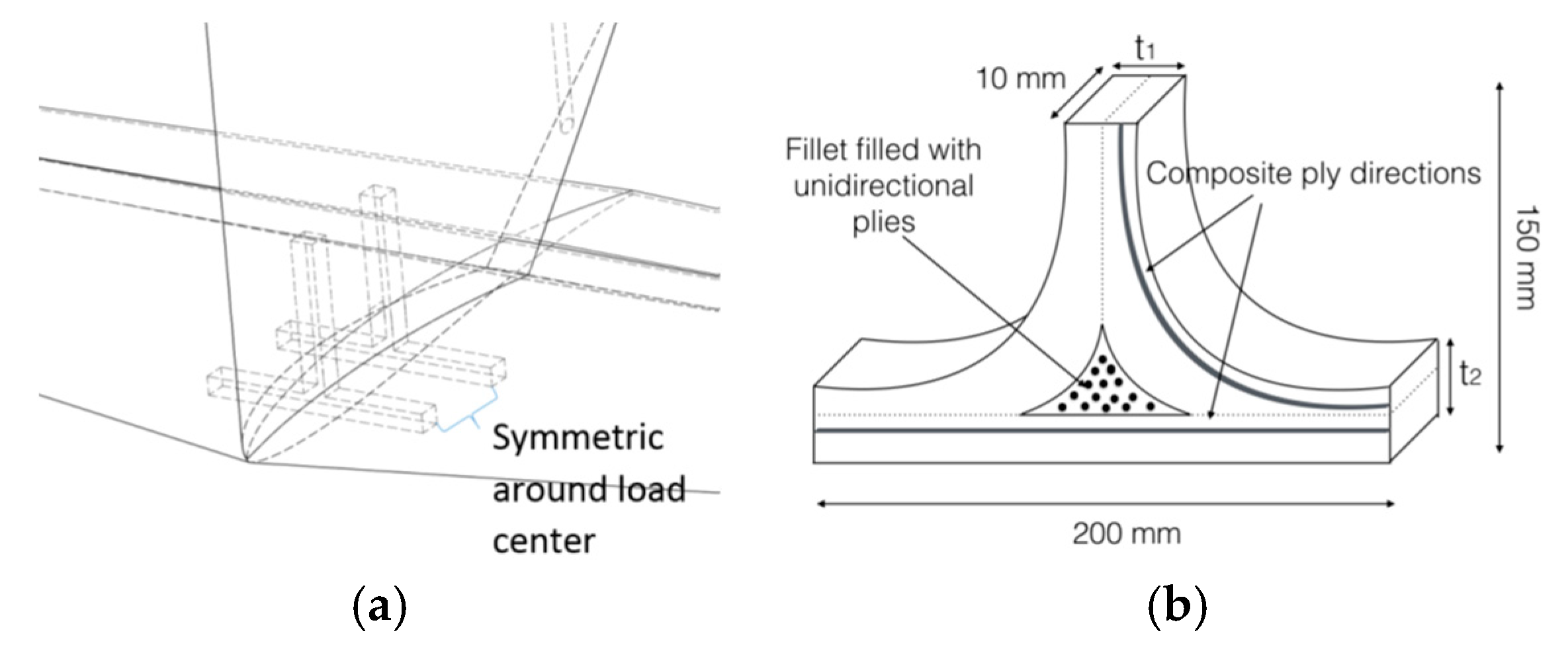
5.1. T-Inserts
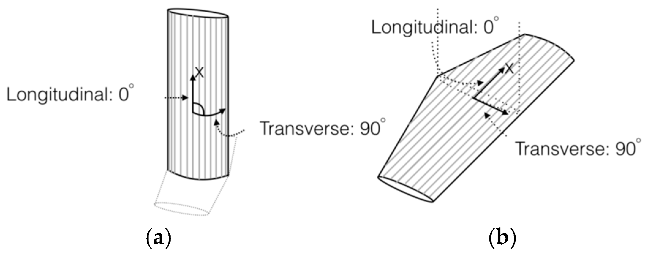
5.2. Centreboard with Integrated Centre Foil
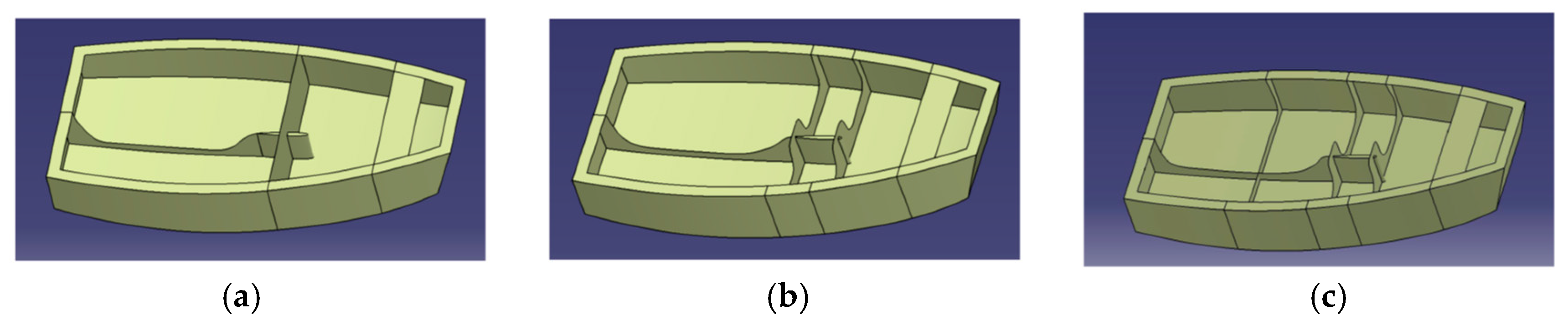
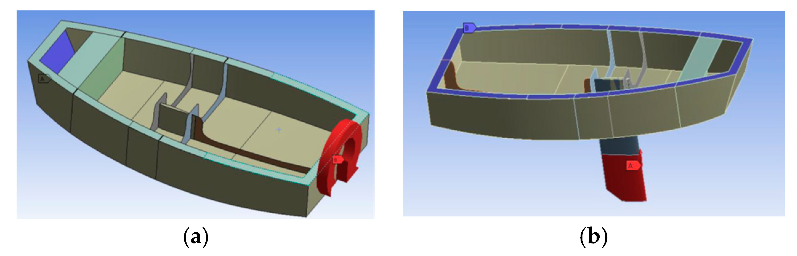
5.3. Centreboard Casing and Hull Reinforcement
6. Results
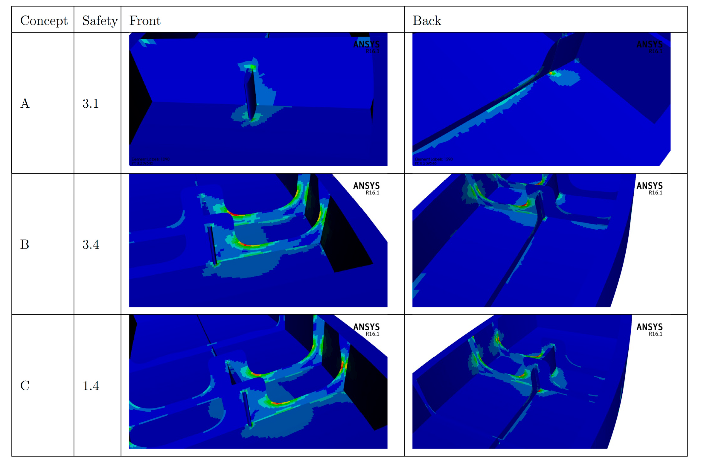
6.1. T-Inserts
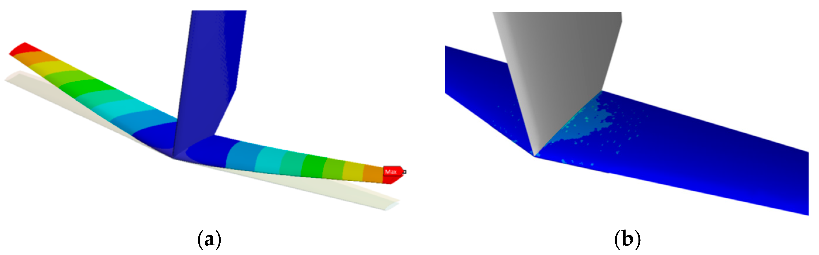
6.2. Centreboard with Integrated Foil
6.3. Centreboard Casing and Hull Reinforcement
7. Conclusions
Acknowledgments
Conflicts of Interest
References
- Andersson, A.; Barreng, A.; Bohnsack, E.; Larsson, L.; Lundin, L.; Sahlberg, R.; Werner, E.; Finnsgård, C.; Persson, A.; Brown, M.; et al. The foiling Optimist. In Proceedings of the 4th International Conference Innovation in High Performance Sailing Yachts, Lorient, France, 28–30 June 2017. [Google Scholar]
- Sheahan, M. The Foiling Phenomenon—How Sailing Boats Got up on Foils to Go Ever-Faster. Available online: http://www.yachtingworld.com/special-reports/the-foiling-phenomenon-66269 (accessed on 8 December 2017).
- ANSYS® Academic Research Mechanical, Release 17.1.
- Andersson, A.; Barreng, A.; Bohnsack, E.; Lundin, L.; Sahlberg, R.; Werner, E. Den Flygande Optimisten. Bachelor’s Thesis, Chalmers University of Technology, Gothenburg, Sweden, 2016. [Google Scholar]
- Allen, D.H. Introduction to the Mechanics of Deformable Solids: Bars and Beams; Springer: New York, NY, USA, 2013. [Google Scholar]
- Zenkert, D.; Battley, M. Foundations of Fibre Composites, 2nd ed.; KTH Paper 96-10; KTH: Stockholm, Sweden, 2011. [Google Scholar]
- The Foiling Optimist (YouTube). Available online: https://www.youtube.com/watch?v=UokOO60dsMU (accessed on 6 October 2017).

| No Stiffening | Concept A | Concept B | Concept C | |
|---|---|---|---|---|
| Torsional stiffness [kNm/rad] | 31.6 | 50.6 (+60%) | 53.7 (+70%) | 48.2 (+53%) |
Publisher’s Note: MDPI stays neutral with regard to jurisdictional claims in published maps and institutional affiliations. |
© 2018 by the authors. Licensee MDPI, Basel, Switzerland. This article is an open access article distributed under the terms and conditions of the Creative Commons Attribution (CC BY) license (https://creativecommons.org/licenses/by/4.0/).
Share and Cite
Oddy, C.; Blomstrand, E.; Johansson, D.; Karlsson, N.; Olofsson, N.; Steen, P.; Fagerström, M.; Asp, L.E.; McVeagh, J.; Brown, M.; et al. Composite Design for a Foiling Optimist Dinghy. Proceedings 2018, 2, 252. https://doi.org/10.3390/proceedings2060252
Oddy C, Blomstrand E, Johansson D, Karlsson N, Olofsson N, Steen P, Fagerström M, Asp LE, McVeagh J, Brown M, et al. Composite Design for a Foiling Optimist Dinghy. Proceedings. 2018; 2(6):252. https://doi.org/10.3390/proceedings2060252
Chicago/Turabian StyleOddy, Carolyn, Elias Blomstrand, Daniel Johansson, Niklas Karlsson, Niklas Olofsson, Petra Steen, Martin Fagerström, Leif E. Asp, John McVeagh, Matz Brown, and et al. 2018. "Composite Design for a Foiling Optimist Dinghy" Proceedings 2, no. 6: 252. https://doi.org/10.3390/proceedings2060252
APA StyleOddy, C., Blomstrand, E., Johansson, D., Karlsson, N., Olofsson, N., Steen, P., Fagerström, M., Asp, L. E., McVeagh, J., Brown, M., & Finnsgård, C. (2018). Composite Design for a Foiling Optimist Dinghy. Proceedings, 2(6), 252. https://doi.org/10.3390/proceedings2060252