Abstract
Liquid impinging jet at the bottom of the annular cavity is a typical case in the process industry. The jet could have an impact at the bottom center or its peripheral section. The profiled annular cylindrical cavity with the installed electricity heater source is investigated in this paper. Thermal contact irreversibility and liquid drag irreversibility are generated within the profiled cavity. Through analytical modeling and experimental verification, a valid model of the entropy generation is established for both states. The results show that the total entropy between the liquid and the bottom is many times greater for the case of the central jet impingement. Within the annular vertical walls are the locations of the maximum or minimum of the entropy. The effectiveness of the liquid heating is greater in the peripheral impact of the liquid. The method and the results are the basis for optimizing the profiled cavity in various optimization geometry parameters. The optimal geometry of the annular cavity exists in such a way that the balance between thermal irreversibility and liquid drag irreversibility leads to the total minimum rate of the entropy generation for the annular cavity.
1. Introduction
Fluid jet impact on curved surfaces and semi-enclosed cavities often happens in thermo-fluid technologies. Many researchers have studied impinging liquid jets on horizontal flat surfaces for established heat transfer. Thus, L. Huang and M. S. El-Genk [1] analyzed and experimentally investigated the heat transfer between heated plate and an impinging circular air jet in order to determine the values of the Nusselt numbers, for small values of the Reynolds number. A. K. Mohanty and A. A. Tawfek [2] measurements the heat transfer from an isothermal plate due to an impinging air jet for different diameters of circular nozzles and Reynolds number. A. H. Beitelmal et al. [3] experimentally studied the effect of the inclination of an impinging air jet on the heat transfer from a heated plate. The experimental investigation of the fluid flow and heat transfer of the rectangular air jet impinging on a heated plate investigated by D. W. Zhou and S. J. Lee [4]. M. Behnia, S. Parneix and P. A. Durbin [5] numerically studied cooling of the heated plate by axisymmetric isothermal turbulent jet. A. V. Nguyen and G. M. Evans [6] studied gas jets impinging onto a gas—liquid interference of a liquid pool using fluid dynamics modeling. D. M. Esparza et al. [7] numerical studied impinging jets over liquid surfaces common in the metallurgy and chemical industry. With regard to analysis and studies show of entropy generation induced by hydraulic and thermal irreversibility A. Bejan [8] gives many different examples generated entropy of different thermal fluid interactions. The minimize the entropy generation of the heat transfer from a thicker plate to a laminar impinging planar jet investigated by G. Ruocco [9]. S. Chen and C. Zheng [10] investigated entropy generation in impinging flow on planar opposing jets. S. Z. Shuja et al. [11] numerically computed local entropy generation rate for the fluid impinging fluid jet on a heated wall. Also, some researchers conducted the analysis and study of entropy generation within the annular channel. O. M. Haddad et al. [12] numerically studied entropy production due to forced convection within the concentric cylindrical annulus. M. Torabi and K. Zhang [13] investigated local and total entropy generation within a composite hollow cylinder with thermal conductivity and heat source. This paper also observed and analyzed entropy generation paradox, i.e., that minimize of the entropy generated does not mean at the same time maximizing the coefficient of performance (COP) of the system. This paradox observed by several researchers, one of them is A. Bejan [14] which is entropy generation paradox observed with counter flow heat exchanger. Also, Shah and Skiepko [15] analyzed 18 types of heat exchangers and came to the conclusion that achieving the maximum coefficient of efficiency does not mean that at the same time established a minimum entropy of the heat exchanger. Similar conclusions come other authors Y. Guo et al. [16], and X. D. Qian and Z. X. Li [17].
This paper presents a comparative analysis of the thermal and hydraulic irreversibility of central and peripheral impinging liquid jets on the heated bottom of a profiled cylindrical cavity. A central liquid impinging on the bottom of a cavity includes both the impact liquid at the center bottom of the profiled cavity and its exit through the peripheral part of the cylindrical cavity. The peripheral impact of liquid on the bottom includes the counter impinging liquid jet in the peripheral part of the bottom and a liquid outlet in the central part of the cavity in the direction of the axis perpendicular to the bottom of the cylindrical cavity. Accordingly, the inlet and outlet of the liquid are such that the two impinging jets are reversed. The overall cylindrical cavity was heated with a heating source of constant temperature located at the bottom. The temperature at the bottom of the cavity was kept constant, while the temperature of the wall of the cylindrical cavity was heated from the bottom. The temperature of the wall cavity is a function of the wall height and the convective heat transfer coefficient between the cylindrical cavity’s inner wall surface and the liquid. The cylindrical cavity was thermally insulated from the outside surface, which was in contact with the surroundings. Also, the inner central channel was thermally insulated from the cylindrical peripheral annular channel. As previously stated, the goal of this research was to identify the difference of thermal and hydraulic irreversibility entropy in such a heating system. The total generated entropy consists of the thermal entropy caused by heat transfer between the cylindrical cavity and the liquid, while the hydraulic entropy results from the friction loss of liquid flow through the cavity. In this analysis, the variables were temperature at the bottom, the liquid flow, the distance from the center of the bottom, and the height of the cylindrical annular channel. This research involved a comparative analysis of thermal and hydraulic irreversibility of the central and peripheral impinging liquid jets on the heated bottom of a cavity. Besides the total entropy, for different conditions, dimensionless sizes as Bejan numbers and irreversibility distribution ratios were compared. This research involved analyzing the entropy generation paradox, i.e., that minimizing entropy generated does not mean maximizing a system’s coefficient of performance (COP).
2. Materials and Methods. The Reasons for this Research. Thermal and Hydraulic Irreversibility
Liquid jet impingement on the bottom of an annular cavity is a common occurrence in the process industry. There are many technical applications in which liquid or some other fluid impinges on a heated wall. Often in thermal and fluid techniques where a liquid impinges on a semi-closed heating cavity and then exits out of the same cavity. This is the case in various vessels with heated bottoms, such as closed profiled pipes, various semi-open channels, etc. Except for the central jet impact, there are situations of liquid counter-impinging on a heated surface. The central and peripheral impacts of liquid on a heated surface may appear within the same semi-closed cavity, which occurs by changing the direction of liquid flow. However, the heat exchange between the liquid and heated cavity causes thermal irreversibility. The flowing liquid, according to friction forces and local hydraulic resistance, generates hydraulic irreversibility. The total generated entropy of the interaction between the cavity and the liquid is equal to the sum of the thermal and hydraulic entropies. Accordingly, there is a need for entropy analysis of the described impact liquid; thus, this research investigated the profiled cavity with a heating source installed on the bottom. Both of the above cases were analyzed under the same conditions and using the same methodology. The aim of this research was to determine the differences in values of generated entropy caused by thermal and hydraulic irreversibility. An additional goal of this research was to establish a mathematical model for dependence-generated entropy of the characteristic geometric parameters of heating cavities. This resulting mathematical model can be a good basis for optimizing the geometric parameters of such cylindrical cavities, such as, for example, minimizing total entropy generated, which could reduce unnecessary thermal and hydraulic losses.
2.1. Central Impinging Liquid Jet on the Bottom of the Cylindrical Cavity
Figure 1 shows how the bottom of the cylindrical cavity was heated with an installed electric heater of constant temperature , while a liquid with inlet temperature and velocity impacted perpendicular to the center of the bottom and exited through the annular cylindrical channel at height .
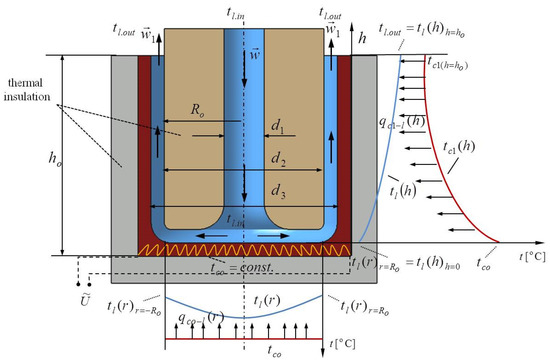
Figure 1.
The central impact liquid on the bottom of the cylindrical cavity.
As mentioned the temperature of cavity bottom is kept constant, while the temperature of the liquid rises from to , while the basis of heat balance, Figure 2, can be expressed by the following expression
and after separation of the variables
and after integration, an expression is obtained for the liquid temperature change from the cavity center to the periphery
where the convective heat transfer coefficient from the bottom of the cavity of the temperature of the liquid of inlet temperature . The liquid after the impact of bottom of the cavity temperature passes through a cylindrical annular channel temperature , which can be obtained based on heat balance,
and obtained, (Equation (5)) after separation of the variables and integration
where the conductivity of the material cavity, the thickness of the vertical wall of the cavity, convection coefficient between the vertical cylindrical wall and liquid temperature. Finding the temperature of the liquid within the annular channel, Figure 2, is obtained after the establishment of heat balance
and after separation of the variables,
by integration and combining with Equation (7) obtained the temperature of the liquid within the annular channel of the heating cavity
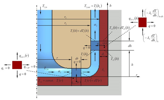
Figure 2.
The thermal interaction between heated cavity and central impact liquid.
Figure 1 shows the representing the temperature of the liquid at the immediate entrance of the annular channel in the vertical at a distance from the center bottom of the cavity. The liquid flow rate was constant and the velocity of the liquid within the annular vertical channel differed in relation to the input velocity of the jet liquid. On the other side, the flowing liquid within the cavity caused a pressure drop of the liquid, which generated additional hydraulic irreversibility. The thermal and hydraulic losses, i.e., thermal and hydraulic irreversibility, together led to the generation of thermal and hydraulic entropy . The total entropy of the liquid and the bottom of the cavity , i.e., the liquid and the annular vertical part of the cavity , is represented by Equations (9) and (10), respectively.
In Equation (9), represents the friction factor of the liquid on impinging liquid jet on the bottom of a cylindrical cavity, while in Equation (10) represents the friction factor of the liquid within the annular part of the cylindrical cavity.
The irreversibility distribution ratio , as ratio hydraulic and thermal irreversibility, gives the possibility to evaluate the influence of losses and their relevance in the process of heat exchange. This ratio according to Equations (9) and (10) can be represented by the following Equations (11) and (12).
The irreversibility distribution ratio refers to the thermo-hydraulic interaction of the bottom and liquid, while the irreversibility distribution ratio refers to the annular channel of the cylindrical cavity.
In accordance with Equations (9) and (10), Bejan number of the liquids and bottom and Bejan number of liquid and annular channel of the cylindrical cavity are represented by Equations (13) and (14), respectively.
This research analyzed the overall effectiveness of the heating profiled cavity as the ratio of the actual heat exchanged in relation to the maximum possible heat exchanged between the heating profiled cavity and the fluid, as in Equation (15).
2.2. The Peripheral Impinging Liquid Jet on the Bottom of the Cylindrical Cavity
As in the previous case, the bottom of the cavity was heated with an electric heater at constant temperature . In this case, a liquid of temperature and velocity passed through the annular vertical channel, impacted the peripheral part, and exited through the central cylindrical channel at height , as shown in Figure 3.
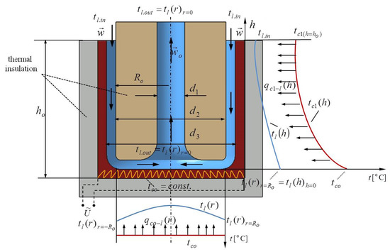
Figure 3.
The peripheral impinging liquid jet on the bottom of the cylindrical cavity.
Previously Equations (1)–(15) were mentioned as characteristics of the central impact of the liquid, Figure 1. Also, in this case only the boundary conditions changed. Therefore, in the annular vertical channel the liquid temperature enters, and an outlet liquid temperature from the channel is the inlet temperature in the periphery of the bottom , Figure 3. From the center of the cavity, liquid vertically exits upward with the temperature . Based on Figure 4 and the established heat balance, the value temperatures of the liquid and the cavity, which were used to find the generated entropy, Bejan number, and irreversibility distribution ratio, were found.
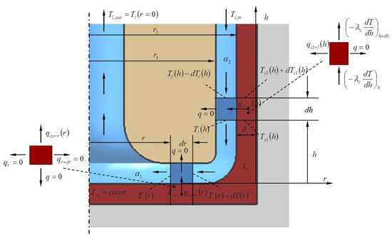
Figure 4.
The thermal interaction between heated cavity and peripheral impact liquid.
3. Results. The Central Impinging Liquid Jet
The Geometrical Change
Figure 5 shows the total generated entropy induced by the thermal irreversibility of the individual impact at the bottom and annular channel as a function of the distance from the center or as a function of the height of the annular channel. The obtained results were varied for two constant temperatures of the bottom: 60 °C and 100 °C. From the point of impact liquid, i.e., , liquid flowed to the annular vertical channel located from the center of the bottom. The thermal entropy increased with increasing distance from the center of the liquid bottom of the cylindrical cavity. The right diagram of Figure 5 shows the individual influence of the annular channel on thermally generated entropy . The flowing liquid moved from the bottom to the top of the annular channel at height . The temperature of the vertical cylindrical wall decreased, while the liquid temperature increased.
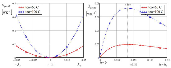
Figure 5.
The thermal entropy of bottom and vertical annular cylindrical channel.
For this reason, there was a decrease in exchanged heat and a reduction of thermally generated entropy . The maximum thermal entropy occured 0.06 m from the bottom, after which the values of entropy decreased. Both diagrams of Figure 5 show that, as expected, the generated entropy values were greater for the higher temperature of 100 °C. Figure 6 shows the total generated entropy induced by the hydraulic irreversibility of the individual impact at the bottom and the vertical annular cylindrical channel.
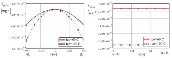
Figure 6.
The hydraulic entropy of the bottom and an annular vertical cylindrical channel.
The values of hydraulic generated entropy were many times lower than the values of entropy induced by thermal irreversibility . Due to the small, insignificant values of hydraulic entropy , the temperature influence at the bottom is clearly visible in both diagrams of Figure 6. The lower temperature of 60 °C at the bottom of the cylindrical cavity reduced the generated entropy caused by hydraulic irreversibility. The dimensionless characteristic ratio for describing the impact of hydraulic generated entropy in relation to thermal entropy generation often uses the irreversibility distribution ratio defined by Equations (11) and (12). In accordance with the left and the right diagrams of Figure 7, it is clear that small value dimensionless ratios directly indicate that the hydraulic generated entropy is negligible in relation to the dominant values of the thermal entropy caused by heat exchange between the cavity and the impacting liquid.
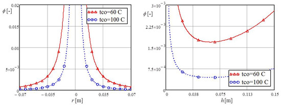
Figure 7.
Irreversibility distribution ratio of the individual influence of the bottom and the vertical annular channel.
In accordance with Figure 3, and in the context of Figure 7 with an increase in the thermal entropy directly decrease values of dimensionless ratio .
For example, in the annular channel, the maximum value of the thermal entropy is at a vertical distance of 0.06 m, as shown in Figure 5, while, at that same distance the irreversibility distribution ratio is at the minimum value. One of the commonly used dimensionless ratios is the Bejan number , presented by Equations (13) and (14), which represents the ratio of the generated entropy caused by thermal irreversibility and the total generated entropy caused by thermal and hydraulic irreversibility. As can be seen by comparing Equations (11) and (12) with Equations (13) and (14) and the diagrams in Figure 7 and Figure 8, the irreversibility ratio and Bejan number are in inverse proportion when the hydraulic irreversibility is negligible compared to the thermal irreversibility, as was the case in this analysis.
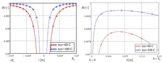
Figure 8.
Bejan number of the individual influence of the bottom and the vertical annular channel.
The values of Bejan number are between 0 and 1; in when heat exchange is far greater than hydraulic loss, the value of this number is about 1. Without heat exchange, the value of this number is zero.
4. Results and Discussion. The Peripheral Impinging Liquid Jet
4.1. The Geometrical Change
In the case of the peripheral impinging jet, shown in Figure 3 and Figure 4, the inlet temperature of the liquid was , while the outlet liquid temperature was the inlet temperature at the periphery of the bottom of the cylindrical cavity, . Figure 3 shows that the liquid from the cylindrical cavity existed in the central channel with a temperature of .
The right diagram of Figure 9 shows that the generated entropy induced by thermal irreversibility was based on the individual impact of heat exchanges in the vertical annular channel and above the bottom of the cylindrical cavity while the temperature at the bottom was varied at 60 °C and 100 °C.
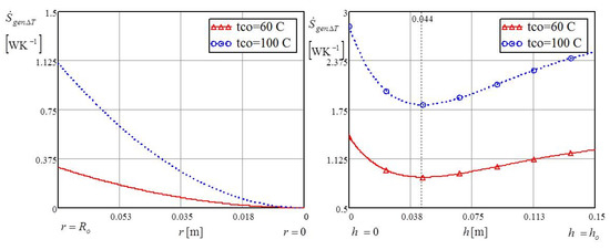
Figure 9.
The thermal entropy of the individual influence of the bottom and the vertical annular channel.
The minimum of the thermal entropy of the vertical channel was found at a distance 0.044 m from the bottom. This was the same position for both test temperatures of 60 °C and 100 °C. The reason for the existence of the minimum thermal entropy in the annular channel was that the liquid temperature and the wall temperature of the annular channel rose in the same direction. Thus, closer to the bottom, the liquid temperature and the wall temperature of the cylindrical cavity both increased towards bottom temperature . The liquid temperature additionally rose from the heat impact of the bottom at constant temperature , and the heated liquid exited the cylindrical cavity with temperature . Decreasing the temperature difference reduced the value of thermal entropy , as sshown in the left diagram of Figure 9. Figure 10 shows that the central impinging jet of liquid within the annular channel had maximum thermal entropy, , while the peripheral liquid impinging within the same channel had minimum thermal entropy.
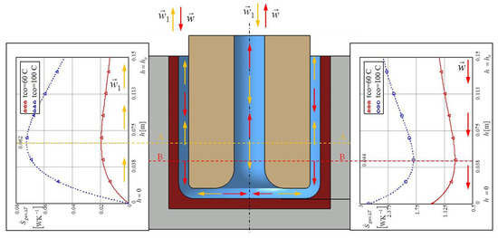
Figure 10.
The comparison of the thermal entropy of the individual influence the vertical annular channel in case central (left) and peripheral (right) impinging jet.
Figure 11 shows that the hydraulic entropy above the bottom of the cylindrical cavity rose from the periphery to the center of the bottom, while hydraulic entropy had a constant value within the annular vertical channel. As in the previous analyses, for the low value of bottom temperature, 60 °C, the hydraulic entropy was greater than with a bottom temperature of 100 °C.
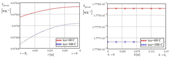
Figure 11.
The hydraulic entropy of the individual influence of the bottom and the vertical annular channel.
Figure 12 shows that the irreversibility distribution ratio of the annular channel was greatest 0.044 m from the bottom. This distance was the same for both temperatures of 60 °C and 100 °C.
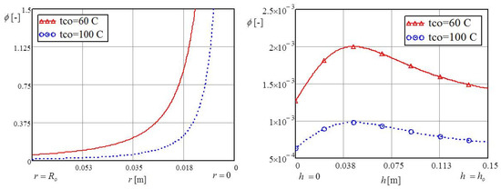
Figure 12.
Irreversibility distribution ratio of the individual influence of the bottom and the vertical annular channel.
The irreversibility distribution ratio was fast growing because of the decrease of the thermal entropy in accordance with the growth of the liquid temperature from to , as shown in the left part of Figure 9. In contrast to the irreversibility distribution ratio, the Bejan number has an inverse function, as shown in Figure 13. Figure 9 shows that the minimum Bejan number, with only minor changes from hydraulic entropy , coincided with the minimum value of thermal entropy .
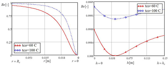
Figure 13.
Bejan number of the individual influence of the bottom and the vertical annular channel.
As previously noted, the values of entropy, irreversibility distribution ratio, and Bejan number shown in Figure 5, Figure 6, Figure 7, Figure 8, Figure 9, Figure 10, Figure 11, Figure 12 and Figure 13 represent the individual effects of the vertical annular channel and the bottom of the cavity on the liquid jet, i.e., its flow through the described profiled cylindrical cavity.
4.2. Change Velocity
Figure 14 shows the individual impact of the bottom and the vertical annular channels on the thermal and hydraulic entropy as a function of the inlet velocity of the liquid . In this analysis, the temperature at the bottom of the cylindrical cavity was kept at a constant value of 50 °C. Since the bottom temperature was constant, increasing the liquid velocity led to greater heat exchange at the bottom with a liquid of inlet temperature which resulted in increased thermal entropy . However, the temperature of the vertical annular wall was not constant at a height .
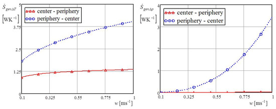
Figure 14.
Thermal and hydraulic entropy for direct and counter impinging liquid jet.
Increasing the liquid velocity increased the intensity of convective heat coefficient ; therefore, there was a decrease in the temperature of the wall and a reduction in heat exchange and thermal entropy . The hydraulic generated entropy rapidly increased with increasing inlet liquid velocity; this increase was evident in all of the cylindrical cavities. As the liquid’s inlet velocity increased, the hydraulic resistance grew many times over, i.e., the hydraulic entropy , which affects the increase of the irreversibility distribution ratio . For the lower bottom temperature of 60 °C, thermal entropy was lower an hydraulic entropy was greater, which caused a greater irreversibility distribution ratio. The higher bottom temperature of 100 °C caused more heat exchange between the cylindrical cavity and the liquid, i.e., led to a higher Bejan number. However, increasing the inlet liquid velocity value decreased the Bejan number, as shown in Figure 15. The reason for this decrease of the Bejan number with increasing inlet liquid velocity is the increase in hydraulic entropy casued by the increased inlet liquid velocity and the total generated entropy .
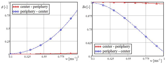
Figure 15.
Irreversibility distribution ratio and Bejan number for direct and counter impinging liquid jet.
Diagrams of the effectiveness of the direct and counter impinging liquid on the heating bottom were established in accordance with Equation (15). Higher values of effectiveness happened with direct liquid impinging on the heated bottom. Higher velocities of liquid intensified the heat exchange, thus causing the vertical part of the annular cavity to cool faster, leading to lower values for effectiveness, as shown in Figure 16.
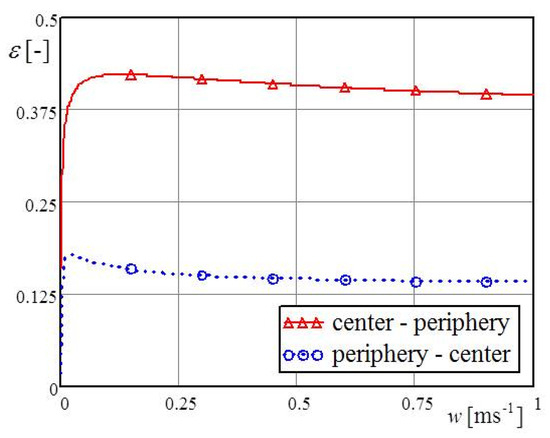
Figure 16.
The effectiveness of direct and counter impinging liquid jet.
5. Entropy Generation Paradox and Entropy Maximum
The minimum generated entropy of a system does not always mean that the maximum coefficient of performance (COP) is evident in a thermo-technique system; this is called the entropy generation paradox. This paradox suggests that decreasing the generated entropy of a system does not mean at the same time increasing the coefficient of performance (COP). As already presented, this research analyzed direct and indirect impinging liquid jets on the heated bottom of a cylindrical cavity and the effects on generated entropy and effectiveness.
Figure 17 presents the generated entropy and the coefficient of performance COP as a function of the height of the cylindrical cavity at different values for the Reynolds number for both the direct, shown on the the left, and counter impinging, shown on the right, liquid jets on the heated bottom of the cylindrical cavity. In the first case, it can be seen that the noticeable interval for the paradox of entropy generation was for heights of the cylindrical vessel above 0.066 m at the Reynolds number of 15,000. Reducing the Reynolds number decreased the interval of the entropy generation paradox. In the counter impinging liquid jet, Figure 17 right, the entropy generation paradox was noticeable for all heights of the cylindrical cavity. Figure 18 shows that maximum generated entropy decreased with increasing height of the cavity ho.
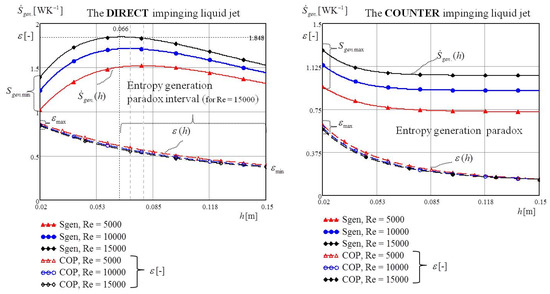
Figure 17.
The entropy generation paradox for direct and counter impinging liquid jet.
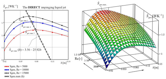
Figure 18.
The maximum entropy generation for direct impinging liquid jet.
6. The Contribution, Limitations, and Benefit of This Work
6.1. The Contribution of This Work
This research demonstrates that a central impinging liquid jet onto a heated profiled cavity generates higher thermal and hydraulic entropies, i.e., total irreversibility.
The directly impinging liquid had greater entropy, while the coefficient of performance was higher with direct impinging compared to peripheral impacting. This resulted in the entropy generation paradox, as mentioned in the previous section.
6.2. The Limitations of This Work
- -
- It did not account for heat exchange between the cylindrical cavity and the environment because it was thermally insulated from the outside.
- -
- It is did not account for heat exchange between the central and peripheral liquid jets.
- -
- The liquid velocity within the channels of the cavity was considered at an average value.
6.3. Benefits of This Work
This research contributes in the following ways:
- -
- Establishes a mathematical model for the thermal and hydraulic irreversibility of direct and counter impinging liquid jets onto a heated cylindrical cavity. This mathematical model can be a basis for minimizing total generated entropy.
- -
- Presents the advantages and disadvantages of direct impinging liquid jets compared to indirect liquid impacting. There is the possibility to choose parameters for liquids or cavities in various industrial applications, both for cooling and heating a cavity with a liquid.
- -
- Establishes the most unfavorable heights, in terms of maximum entropy, of a cavity for a direct impinging liquid jet as a function of different values of the Reynolds number.
7. Validation Results
The mathematical model was validated with experimental testing of the central and peripheral impinging liquid jets in a profiled cavity at the same boundary conditions, as well as in mathematical analysis. The generated entropy caused by the thermal irreversibility and hydraulic entropy was indirectly determined by direct measurement of the characteristic temperatures, pressures, and volumetric flow of liquid. In order to determine the thermal entropy , average measurements were taken of of temperatures , the temperature of the cylindrical vertical wall , and inlet and outlet temperature of the liquid, and , respectively. Also, measurements were taken of the average heat flux at the bottom of the cavity, surface , and the average heat flux of the annular channel wall, surface . In order to determine the hydraulic entropy measurements were taken of liquid pressure at entrance and exit of the cylindrical cavity. The volumuteric liquid flow was varied for three values: 0.00039, 0.00078, and 0.00117 m3 s−1. Figure 19 shows that yhe total generated entropy resulting from the experiment , induced by thermal and hydraulic irreversibility, was determined using the following expression:
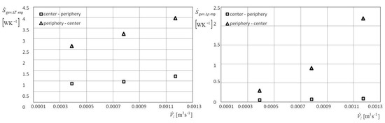
Figure 19.
Experimental values of thermal and hydraulic entropy for direct and counter impinging liquid jet.
Figure 20 presents the expermental results as based on Equation (16) and the already mentioned basic definitions of Bejan number and the irreversibility distribution ratio .
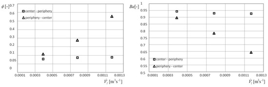
Figure 20.
Experimental values of irreversibility distribution ratio and Bejan number for direct and counter impinging liquid jet.
Also, effectiveness was experimentally determined in accordance with the left side of Equation (15). Figure 21 shows comparative diagrams for direct and peripheral impinging on the heated bottom.
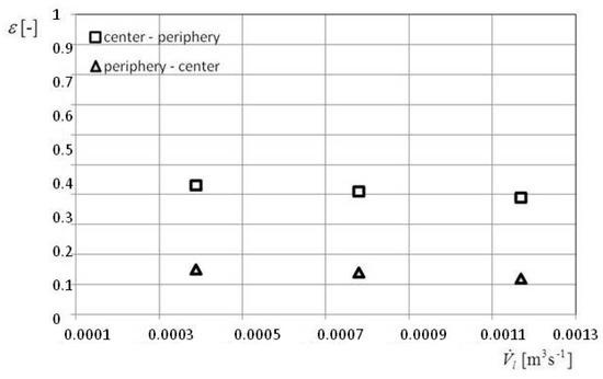
Figure 21.
Experimental values of the effectiveness for direct and counter impinging liquid jet.
By comparing the experimental results with the results of mathematical modeling, it can be concluded that the used mathematical model satisfactorily describes the irreversibility of thermal hydraulic system, as analyzed in this paper.
8. Conclusions
This paper presents the investigation and analsysis of entropy for two cases of liquid impinging jets within a profiled cylindrical cavity. In the first case, the liquid jet impacted the center of the bottom and exited through the peripheral annular channel, while the second case involved a liquid impinging jet. Both of the above cases involved mathematical modeling of thermal and hydraulic entropy, irreversibility distribution ratio, and the Bejan number as a function of the radius of the bottom of the cavity and the height of the peripheral annular channel. Also, this research investiagted the effects of varying liquid input velocities, with constant geometric dimensions of the cylindrical cavity, on thermal and hydraulic irreversibility. The research conclusions are as follows:
- -
- The total generated entropy for a central impinging liquid jet of constant inlet velocity is lower than for a counter impinging liquid jet on the peripheral part of the bottom of the cylindrical cavity.
- -
- A central impinging liquid jet increases the values of the thermal and hydraulic entropy on the bottom by many times greater than its on the vertical annular channel. However, the total thermal entropy of the cylindrical cavity is many times greater than the total hydraulic generated entropy.
- -
- A peripheral impinging liquid jet influences thermal entropy at the bottom of the cylindrical cavity less than on the vertical annular channel. The hydraulic entropy of both the bottom and annular vertical channel of the cylindrical cavity differ negligibly in relation to the previous case.
- -
- Either the minimum or maximum thermal entropy appears within the annular channel. This depends on whether the liquid flow enters or exits through the annular channel, or whether the liquid centrally or peripherally impinges on the bottom of the cavity.
- -
- The research has also shown that the effectiveness of the heating profiled cavity is greater in the case of a direct impinging liquid jet on the bottom of the cavity.
- -
- The above can be applied and in the case of a profiled cylindrical cavity cooled with liquid.
Future Research Directions
A mathematical model of entropy generation caused by thermal and hydraulic irreversibility was developed based on the analyses and tests in this study. This mathematical model can provide a good basis for optimizing this system. For example, it can be used for minimizing thermal and hydraulic irreversibility.
References
- Huang, L.; El-Genk, M.S. Heat transfer of an impinging jet on a flat surface. Int. J. Heat Mass Transf. 1994, 37, 1915–1923. [Google Scholar] [CrossRef]
- Mohanty, A.K.; Tawfek, A.A. Heat transfer due to a round jet impinging normal to a flat surface. Int. J. Heat Mass Transf. 1993, 36, 1639–1647. [Google Scholar] [CrossRef]
- Beitelmal, A.H.; Saad, M.A.; Patel, C.D. The effect of inclination on the heat transfer between a flat surface and impinging two-dimensional air jet. Int. J. Heat Fluid Flow 2000, 21, 156–163. [Google Scholar] [CrossRef]
- Zhou, D.W.; Lee, S.J. Forced convective heat transfer with impinging rectangular jets. Int. J. Heat Mass Transf. 2007, 50, 1916–1926. [Google Scholar] [CrossRef]
- Behnia, M.; Parneix, S.; Durbin, P.A. Prediction of heat transfer in an axisymmetric turbulent jet impinging on a flat plate. Int. J. Heat Mass Transf. 1998, 41, 1845–1855. [Google Scholar] [CrossRef]
- Nguyen, A.V.; Evans, G.M. Computational fluid dynamics modeling of gas jets impinging onto liquid pools. Appl. Math. Model. 2006, 30, 1472–1484. [Google Scholar] [CrossRef]
- Muñoz-Esparza, D.; Buchlin, J.-M.; Myrillas, K.; Berger, R. Numerical investigation of impinging gas jets onto deformable liquid layers. Appl. Math. Model. 2012, 36, 2687–2700. [Google Scholar] [CrossRef]
- Bajan, A. Entropy Generation through Heat and Fluid Flow; John Wiley & Sons: New York, NY, USA, 1982. [Google Scholar]
- Ruocco, G. Entropy generation in conjugate heat transfer from a discretely heated plate to an impinging confined jet. Int. J. Heat Mass Transf. 1997, 24, 201–210. [Google Scholar] [CrossRef]
- Chen, S.; Zheng, C. Entropy generation in impinging flow confined by planar opposing jets. Int. J. Therm. Sci. 2010, 49, 2067–2075. [Google Scholar] [CrossRef]
- Shuja, S.Z.; Yibas, B.S.; Budair, M.O. Local entropy generation in an impinging jet: Minimum entropy concept evaluating various turbulence models. Comput. Methods Appl. Mech. Eng. 2001, 190, 3623–3644. [Google Scholar] [CrossRef]
- Haddad, O.M.; Alkam, M.K.; Khasawneh, M.T. Entropy generation due to laminar forced convection in the entrance region of a concentric annulus. Energy 2004, 29, 35–55. [Google Scholar] [CrossRef]
- Torabi, M.; Zhang, K. Temperature distribution and classical entropy generation analyses in an asymmetric cooling composite hollow cylinder with temperature-dependent thermal conductivity and internal heat generation. Energy 2014, 73, 484–496. [Google Scholar] [CrossRef]
- Bejan, A. Advanced Engineering Thermodynamics; John Wiley & Sons: New York, NY, USA, 1998. [Google Scholar]
- Shah, R.K.; Skiepko, T. Entropy generation extreme and their relationship with heat exchanger effectiveness—Number of transfer unit behavior for complex flow arrangements. J. Heat Transf. 2004, 126, 994–1002. [Google Scholar] [CrossRef]
- Guo, Z.Y.; Liu, X.B.; Tao, W.Q.; Shah, R.K. Effectiveness—Thermal resistance method for heat exchanger design and analysis. Int. J. Heat Mass Transf. 2010, 53, 2877–2884. [Google Scholar] [CrossRef]
- Qian, X.D.; Li, Z.X. Analysis of entransy dissipation in heat exchangers. Int. J. Therm. Sci. 2011, 50, 608–614. [Google Scholar] [CrossRef]
Publisher’s Note: MDPI stays neutral with regard to jurisdictional claims in published maps and institutional affiliations. |
© 2018 by the author. Licensee MDPI, Basel, Switzerland. This article is an open access article distributed under the terms and conditions of the Creative Commons Attribution (CC BY) license (https://creativecommons.org/licenses/by/4.0/).