Proceeding Paper

An Evaluation of Heat Transfer Enhancement Technique in Flow Boiling Conditions Based on Entropy Generation Analysis: Micro-Fin Tube †

by
Mohammad Ali Abdous
School of Mechanical Engineering, Iran University of Science and Technology, Tehran 16846-13114, Iran
Presented at the 4th International Electronic Conference on Entropy and Its Applications, 21 November–1 December 2017; Available online: http://sciforum.net/conference/ecea-4.
Proceedings 2018, 2(4), 149; https://doi.org/10.3390/ecea-4-05002
Published: 20 November 2017

Abstract

:
The flow boiling heat transfer is one of the common phenomenon happening in the industries. The micro-fin tubes are one of the geometries widely used to enhance heat transfer rate in boiling condition. The entropy generation analysis is presented with its formulation to find precisely the best operating conditions in micro-fin tubes in terms of geometrical parameters and flow conditions. This analysis shows important aspects of losses in fluid systems undergoing boiling. The losses include thermal loss related to the heat transfer and hydraulic one related to the pressure drop. The relevant terms are described for both of these losses. The optimum tube diameter under specified conditions is found. The effect of different flow conditions such as mass velocity, inlet vapor quality on contribution of pressure drop and heat transfer in entropy generation is discussed. It is discovered that there is a desirable set of conditions of fluid flow and micro-fin geometrical shape for which the minimum entropy generation is reached.

1. Introduction

Various researchers have conducted studies on the entropy generation in heat exchangers. Manjunath and Kaushik [3] performed a review on the importance of first and second law of thermodynamics in entropy generation analysis. Also, the application of the entropy generation analysis in design and optimization of engineering systems was reviewed by Sciacovelli et al. [7].
Naphon [5] presented experimental results as well as theoretical formulations for entropy generation and exergy destruction in a tubular heat exchanger. They included the effect of fluid temperature variations along the length of the heat exchanger. Their results indicated that for a constant hot water mass flux, the entropy generation number increases for higher inlet temperatures. Ye and Lee [11] investigated a numerical model for fin-and-tube condensers with complex refrigerant circuit based on entropy generation. Compared to the condensers with simple refrigerant path, there was an appreciable enhancement in heat transfer performance. Manjunath and Kaushik [4] conducted an analytical analysis on an unbalanced heat exchanger based on the second law of thermodynamics. They varied the length-to-diameter ratio for both counter flow and parallel flow configurations. Their results showed that the dimensions for optimum heat exchanger design, namely length-to-diameter ratio, can be found.
Some studies have been published with the focus on the entropy generation analysis in two-phase flows in heat exchanger. Kaushik and Manjunath [2] analyzed a single pass double pipe two phase flow heat exchanger. Based on the second law, they mainly considered three two-phase flow regimes. They reported their results of entropy generation number by varying parameters such as diameter, mass velocity, wall superheat, and quality.
Few efforts have been made to investigate entropy generation in two-phase flows in tubes and channels. The local entropy generation for diabatic two-phase flow was studied by Revellin et al. [6]. They performed a study on local entropy generation of two-phase diabatic flows. In order to analyze the entropy generation in saturated flow boiling in pipes, they developed two models, namely separated flow model and mixture model. Entropy generation in the evaporator of a vapor compression refrigeration cycle was inspected by Türkakar and Okutucu-Özyurt [8] by studying the variations of channel height and width, the heat flux, the mass flow rate and several other parameters. They concluded that increasing heat flux increases the entropy generation. Abdous et al. [1] conducted a comprehensive study on using of entropy generation analysis in a helically coiled tube in flow boiling condition under a constant heat flux. They investigated changing of important flow parameters such as saturation temperature, heat flux and vapor quality on entropy generation. The optimum coil diameter was found based on their analysis.
The main goal of this study is to find the optimum diameter of the micro-fin tube by means of entropy generation analysis. Then, variation of flow conditions such as vapor quality and mass velocity is studied on entropy generation and contribution of pressure drop and heat transfer one.

2. Mathematical Modeling

Suppose a mixture of liquid and vapor in saturated conditions enters a tube under constant wall heat flux. The mathematical model of saturated two-phase flow is based on the second law of thermodynamics. For a finite control volume of length d l , the total entropy generation per unit length S ˙ gen can be written as:
S ˙ gen = m ˙ d ( x s v + ( 1 x ) s l ) Q ˙ T w d l
where m ˙ is the total mass flow rate, T w denotes the channel wall temperature, Q ˙ is the rate of heat transfer into the control volume and s is the entropy. The vapor quality can be defined as Equation (2):
x = m ˙ v m ˙ v + m ˙ l
The entropy generation per unit length ( S ˙ gen ) becomes:
S ˙ gen d l = m ˙ ( s lv d x + x d s v + ( 1 x ) d s l ) Q ˙ T w
And, the values of d h v and d h l are:
d h v = T v d s v + v v d p v
d h l = T l d s l + v l d p l
Therefore, in Equation (3), the values of d s v and d s l are obtained from Equations (4) and (5). Assuming T v = T l = T sat , d p v = d p l and s lv = h lv T sat in saturated flow boiling, the entropy generation per unit length ( S ˙ gen ) can be rewritten as:
S ˙ g e n d l = m ˙ T s a t ( h lv dx + xd h v + ( 1 x ) d h l ) Q ˙ T w m ˙ ( x v v + ( 1 x ) v l ) T sat d p
S ˙ gen d l = m ˙ T sat d h tp Q ˙ T w m ˙ v tp d p T sat
Using the first law of thermodynamics Q ˙ is obtained as:
Q ˙ = m ˙ d h tp
Simplifying Equation (7) by using Equation (8), the final term for the entropy generation per unit length is
S ˙ gen = m ˙ [ d h tp d l ( 1 T sat 1 T w ) v tp T sat d p d l ]
Two contributions can be understood of the entropy generation per unit length ( S ˙ gen ) in Equation (9). The heat transfer contribution [(Equation (10)], and the pressure drop contribution [Equation (11)];
S ˙ gen , ht = m ˙ d h tp d l ( 1 T sat 1 T w )
S ˙ gen , pd = m ˙ v tp T sat ( d p d l )
d p d l being the two-phase pressure drop of tube covering gravitational and accelerative pressure drops. The relationship between vapor quality and void fraction is obtained from (Woldesemayat and A. J. Ghajar, [9]);
ε = U sv U sv ( 1 + ( U sl U sv ) ( ρ v ρ l ) 0.1 ) + 2.9 [ g D σ ( 1 + cos θ ) ( ρ l ρ v ) ρ l 2 ] 0.25 ( 1.22 + 1.22 sin θ ) P atm P system
where, U sl and U sv are the superficial liquid and gas velocity, respectively, g is the gravitational acceleration and the θ is tube inclination angle. ρ v and ρ l are respective densities of vapor and liquid. σ is the fluid surface tension. In the case of a micro-fin tube, D is the tube hydraulic diameter. P atm is the atmospheric pressure and the P system is the system pressure.

3. Results and Discussions

Figure 1 shows a schematic of a tube-in-tube straight heat exchanger designed by Wongsangam et al. of a micro-fin tubes for obtaining correlations of heat transfer coefficient and frictional pressure drop. HFC-134a flows in the inner tube, while heating water flows in the annulus in counter direction.

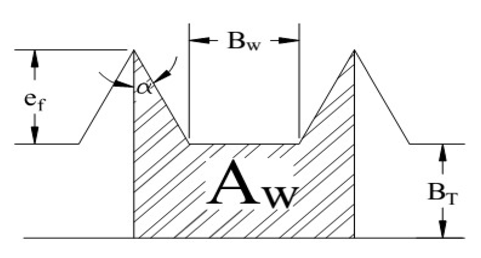
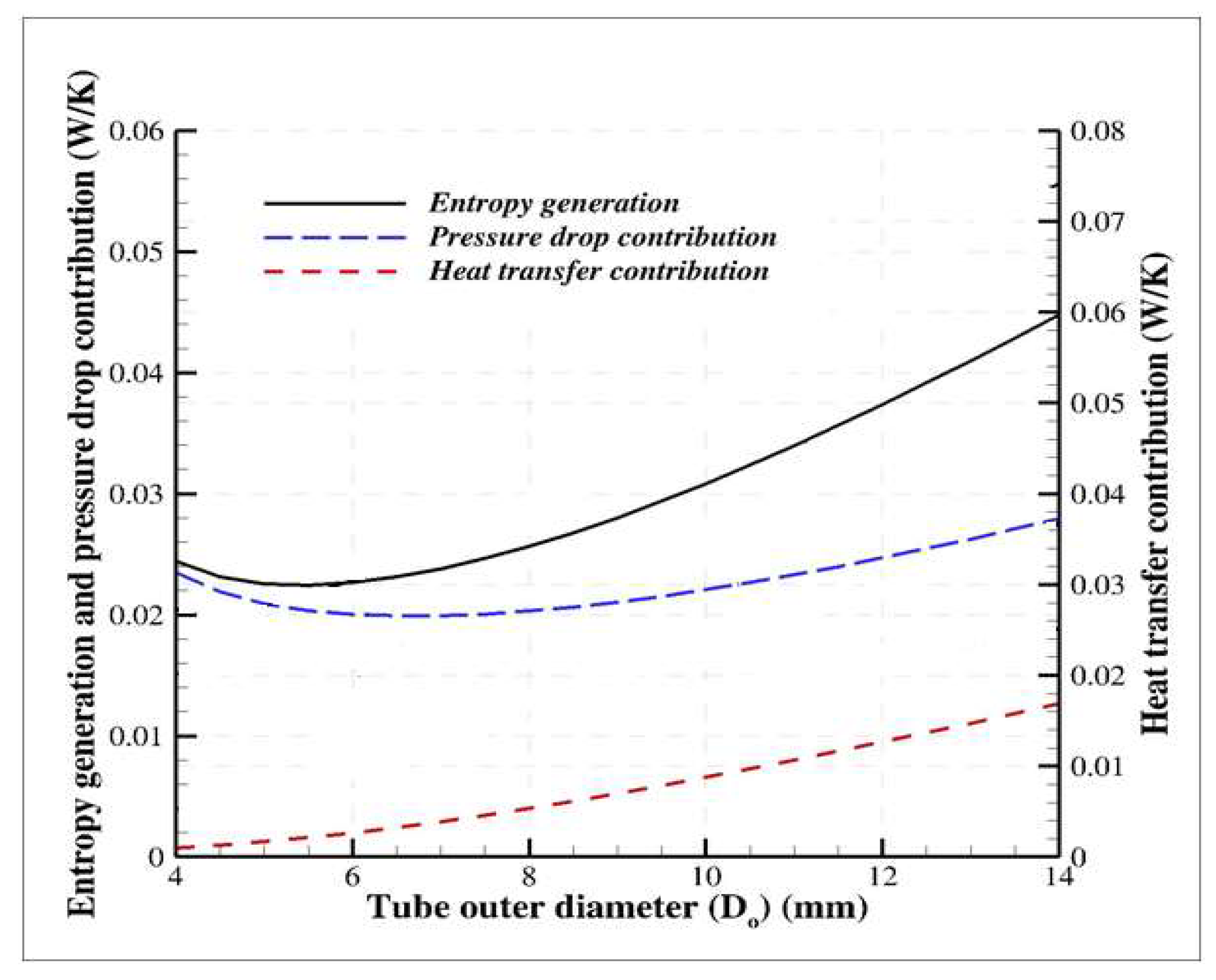
3.1. The Geometrical Parameters of the Micro-Fin Tube

First, the geometry of micro-fin must be demonstrated here by some details. Important Parameters height ( e f ), the bottom width ( B w ), the bottom thickness ( B T ) and the angle α are shown in Figure 2. Symbol ( N ) denotes the number of fins for the micro-fin tube.
  S p is the distance between two tips of fins (Wongsa-ngam et al., [10]);.
S p = B w + 2 e f cos ( α )
The cross sectional tube wall area per fin A w and cross sectional flow area A c are defined as follow;
A w = e f 2 tan ( α ) + ( 2 e f tan ( α ) + B w ) B T
A c = π D o 2 4 N A w
The hydraulic diameter is;
D h = 4 A c cos ( β ) N S p
The alpha angle (α) in Figure 2 is:
α = tan 1 ( π D i N B W 2 e f )
The flow conditions are constant and presented in Table 1.
The increase in the value of the mass flow rate is directly proportional to the square of tube outer diameter ( D o 2 ). In the micro-fin tube, the mass flow rate ( m ˙ = G A c ) varies with   A c (Equation (19)). In addition, at constant heat flux, the value of total heat rate entering the micro-fin tube is proportional to the tube outer diameter ( D o ). Therefore, the vapor quality decreases which leads to increase in the value of mixture density. Consequently, at constant mass velocity, the mixture velocity and pressure drop decrease. At low values of tube outer diameter ( D o ), the decrease in pressure drop causes a reduction in pressure drop contribution. Gradually, the increase in the value of tube outer diameter ( D o ), leads to an increase in pressure drop contribution.
Therefore, at this region the increase in the value of mass flow rate becomes the dominant parameter in increasing the pressure drop contribution as shown in Figure 3. Consequently, the minimum point appears in the pressure drop contribution for the micro-fin one. Finally, the tube with 5 mm outer diameter is recognized as an optimum for mentioned conditions.

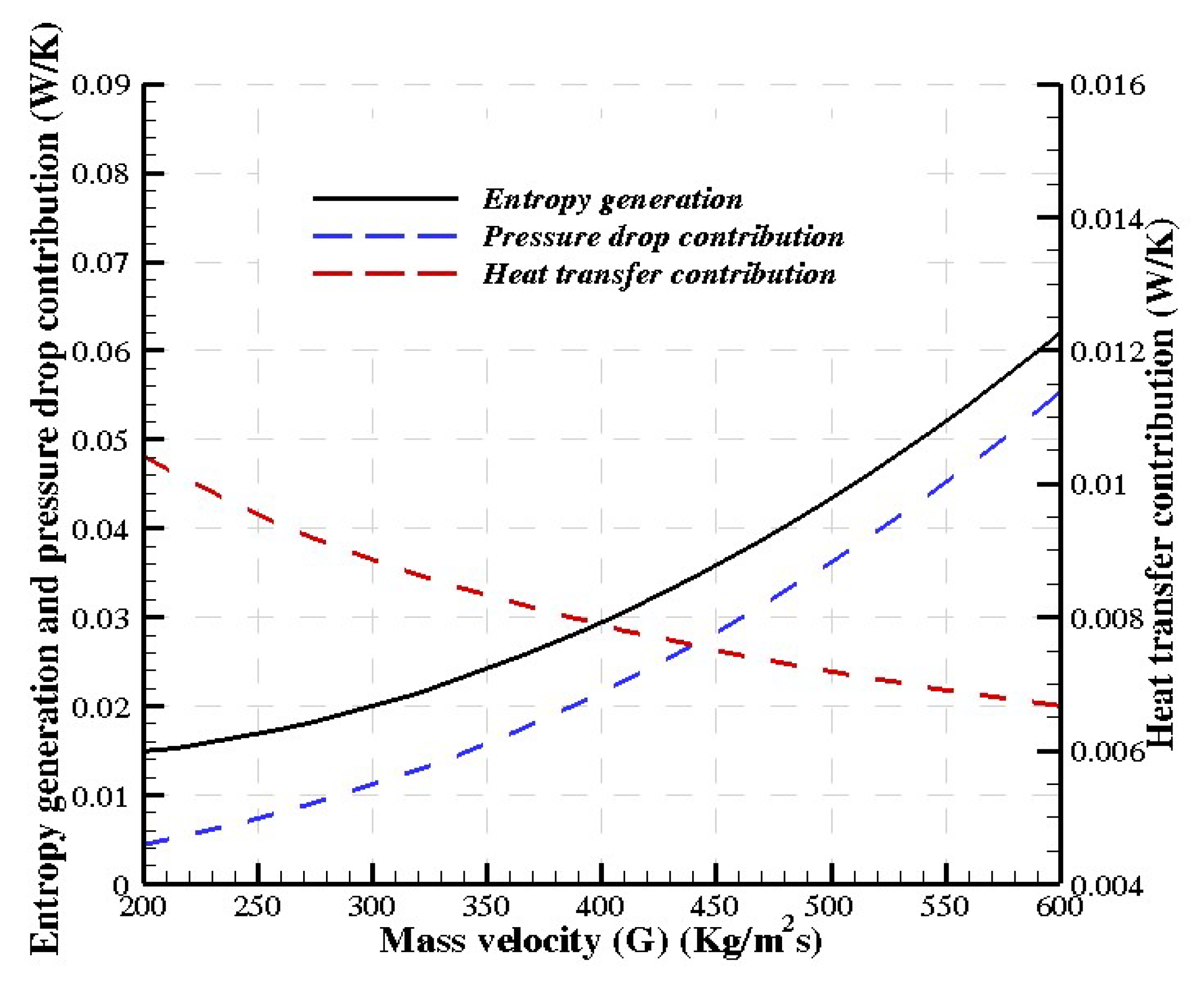
3.2. Change in Flow Conditions

In this section, the geometrical parameters for the micro-fin tube are assumed to match with the study of Wonsagam et al. as mentioned in Table 3.
Assuming the geometrical parameters in Table 4, the effect of changing in the flow conditions such as mass velocity ( G ), inlet vapor quality ( x in ) is studied.
The variation of entropy generation, and the respective pressure drop and heat transfer contributions are plotted versus mass velocity ( G ) in Figure 4 for micro-fin tube. At constant heat flux, as the value of mass velocity ( G ) increases, the heat transfer coefficient rises (Wongsangam et al., [10]). Therefore, the heat transfer contribution in entropy generation decreases (Equation (10)). Moreover, the increase in G results in an increase in the frictional losses for both tubes. Thus, the pressure drop contribution in entropy generation increases. Figure 5 illustrates the effect of variation of inlet vapor qualities ( x in ) on total entropy generation and its components for the micro-fin tube (Table 3).
The flow conditions are presented in Table 5. The reduction in two-phase mixture density at constant mass velocity (450 kgm−2s−1), is the result of increasing the inlet vapor quality from 0.1 to 0.5. Therefore, the mixture velocity and pressure drop contribution increasing gradually. The rising the value of inlet vapor quality results in higher heat transfer coefficients (Wongsangam et al., [10]). This means that for higher x in the heat transfer contribution is lower.

4. Conclusions

Enhancement of heat transfer rate is possible using various passive methods. Creating micro-fins in the tube is one of the passive methods to augment the heat transfer coefficient. To evaluate this method, the entropy generation analysis is used in flow boiling. By using entropy generation analysis, the tube optimum diameter is found for specified flow conditions. The variation of flow parameters such as mass velocity and vapor quality is considered. It is showed that, by increasing both of these factors, the contribution of pressure drop increases while the heat transfer one decreases.

Conflicts of Interest

The authors declare no conflict of interest.

Abbreviations

The following abbreviations are used in this manuscript
ACross section (m2)
A c Cross sectional flow area (m2)
A W Cross sectional tube wall area per fin (m2)
BeBejan number (−)
B T Bottom thickness (m)
B W Bottom width (m)
d l Element discretization (m)
D h Hydraulic diameter (m)
D o Tube outer diameter (m)
e f Fin height (m)
GMass velocity ( kgm 2 s 1 )
HSpecific enthalpy ( Jkg 1 )
LLength (m)
m ˙ Mass flow rate ( kgs 1 )
NNumber of fins(−)
N s Entropy generation number (−)
PPressure (Pa)
PPerimeter (m)
QHeat flux ( Wm 2 )
Q ˙ Heat rate (W)
SSpecific entropy ( JK 1 )
S ˙ gen Entropy generation per unit length ( Wm 1 K 1 )
TTemperature (˚C)
UConvective heat transfer coefficient ( Wm 2 K 1 )
U sl Liquid superfacial velocity ( m s 1 )
U sv Gas superfacial velocity ( m s 1 )
Greek symbols
ε Void fraction (−)
α Fin angle (deg.)
ρ Density ( kgm 3 )
β Fin spiral angle (deg.)
v Specific volume (m3 kg 1 )
Subscripts
htHeat transfer
inInlet
lLiquid
pdPressure drop
satSaturation
tpTwo-phase
vVapor
wWall
xVapor quality

References

  1. Abdous, M.A.; Saffari, H.; Avval, H.B.; Khoshzat, M. Investigation of entropy generation in a helically coiled tube in flow boiling condition under a constant heat flux. Int. J. Refrig. 2015, 60, 217–233. [Google Scholar] [CrossRef]
  2. Kaushik, S.C.; Manjunath, K. Second law analysis of condenser by using new heat transfer and pressure drop model based on flow regimes. Int. J. Exergy 2011, 9, 255–279. [Google Scholar] [CrossRef]
  3. Manjunath, K.; Kaushik, S.C. Second law thermodynamic study of heat exchangers: A review. Renew. Sustain. Energy Rev. 2014, 40, 348–374. [Google Scholar] [CrossRef]
  4. Manjunath, K.; Kaushik, S.C. Second law efficiency analysis of heat exchangers. Heat Transf. Res. 2015, 44, 89–108. [Google Scholar] [CrossRef]
  5. Naphon, P. Study on the exergy loss of the horizontal concentric micro-fin tube heat exchanger. Int. Commun. Heat Mass Transf. 2011, 38, 229–235. [Google Scholar] [CrossRef]
  6. Revellin, R.; Lips, S.; Khandekar, S.; Bonjour, J. Local entropy generation for saturated two-phase flow. Energy 2009, 34, 1113–1121. [Google Scholar] [CrossRef]
  7. Sciacovelli, A.; Verda, V.; Sciubba, E. Entropy generation analysis as a design tool—A review. Renew. Sustain. Energy Rev. 2015, 43, 1167–1181. [Google Scholar] [CrossRef]
  8. Türkakar, G.; Okutucu-Özyurt, T. Entropy generation analysis and dimensional optimization of an evaporator for use in a microscale refrigeration cycle. Int. J. Refrig. 2015, 56, 140–153. [Google Scholar] [CrossRef]
  9. Woldesemayat, M.A.; Ghajar, A.J. Comparison of void fraction correlations for different flow patterns in horizontal and upward inclined pipes. Int. J. Multiph. Flow 2007, 33, 347–370. [Google Scholar] [CrossRef]
  10. Wongsa-ngam, J.; Nualboonrueng, T.; Wongwises, S. Performance of smooth and micro-fin tubes in high mass flux region of R-134a during evaporation. Heat Mass Transf. 2002, 40, 425–435. [Google Scholar] [CrossRef]
  11. Ye, H.-Y.; Lee, K.-S. Refrigerant circuitry design of fin-and-tube condenser based on entropy generation minimization. Int. J. Refrig. 2012, 35, 1430–1438. [Google Scholar] [CrossRef]
Figure 1. The schematic figure of the micro-fin tube-in-tube heat exchangers (Wongsa-ngam et al., [10]).
Proceedings 02 00149 g001
Figure 2. The cross sectional view of the micro-fin tube (Wongsa-ngam et al., [10]).
Proceedings 02 00149 g002
Figure 3. The entropy generation, pressure drop contribution and the heat transfer one for the micro-fin tube with flow conditions (Table 1) and geometrical parameters (Table 2).
Proceedings 02 00149 g003
Figure 4. The variation of entropy generation, pressure drop contribution and heat transfer one versus mass velocity ( G ) for the micro-fin tube geometrical parameters (Table 3) with assumed flow conditions (Table 4).
Proceedings 02 00149 g004
Figure 5. The variation of entropy generation, pressure drop contribution and heat transfer one versus inlet vapor quality ( x in ) for the micro-fin tube geometrical parameters (Table 3) with assumed flow conditions (Table 5).
Proceedings 02 00149 g005
Table 1. The assumed flow parameters.
G   ( k g m 2 s 1 ) q   ( k W m 2 ) T s a t   ( ° C ) x i n
40010150.2
Table 2. The assumed geometrical parameters when the tube outer diameter ( D o ) changes from 4 mm to 14 mm.
e f   ( mm ) B w   ( mm ) N B T   ( mm ) L (m)
0.20.27600.32.5
Table 3. The geometrical parameters for the micro-fin tube.
D o   ( mm )   e f   ( mm ) B w   ( mm ) N B T   ( mm ) L (m)
9.520.2 0.27600.32.5
Table 4. The assumed flow conditions when the value of mass velocity ( G ) changes from 200   k g m 2 s 1   600   k g m 2 s 1 .
q   ( k W m 2 ) T s a t   ( ° C ) x i n
10150.2
Table 5. The flow conditions when inlet vapor quality ( x in ) changes from 0.1–0.5.
  q   ( k W m 2 ) T s a t ( ° C ) G   ( k g m 2 s 1 )
1015450
Publisher’s Note: MDPI stays neutral with regard to jurisdictional claims in published maps and institutional affiliations.

