1. Introduction
Wheeled mobile robots (WMRs) are employed in many areas such as logistics, inspection and maintenance, security and defense, agriculture, medical care, home care, urban transport, planetary exploration and surveillance operations. Due to the precision required during the performance of a WMR, the robot should properly be calibrated, and the positional error should be improved, before implementation in real field. Developing effective calibration techniques have recently been interested for robotic systems [
1]. They include odometry, 3D camera error detection, active beacons, gyroscope and magnetic compasses [
2,
3,
4,
5,
6]. Odometry uses the information of positional sensors attached to each actuator to estimate change in position over time. The odometry method is applied to correct errors of different types of WMRs [
2,
3].
The calibration of WMRs using odometry approach has been performed by researchers and engineers. Correcting systematic errors with localization based on magnetic fields has been discussed in [
6]. University of Michigan Benchmark (UMBmark) method was introduced to measure odometry errors in differential drive mobile robots [
7]. The UMBmark was then employed to reduce positional errors of several WMRs with differential drive mechanism. The author proposed a new technique to reduce both systematic [
2,
8] and non-systematic [
3] errors. This context proposes a kinematic-based calibration method, which is simple to implement and applicable to all types of wheeled mobile robots including differential drive, omnidirectional and multi-degree of freedom (DOF) WMRs. The proposed technique is employed to correct the motion of a two-wheeled mobile robot.
The rest of this paper is organized as follows. Sources of positional errors are described in
Section 2. Kinematic modeling of WMRs are presented in
Section 3.
Section 4 documents the development of the proposed calibration method.
Section 5 describes the prototyped mobile robot, followed by experimental results in
Section 6.
Section 7 outlines the conclusions of this research.
2. Positional Errors
The accuracy of robot movement and the amount of positional errors depend on the sources causing both systematic and nonsystematic errors. Systematic errors originate from control and mechanical elements due to imperfections from design to fabrication. Non-systematic errors are independent of the robot structure and its characteristics, and are defined unwanted errors produced due to surface irregularities.
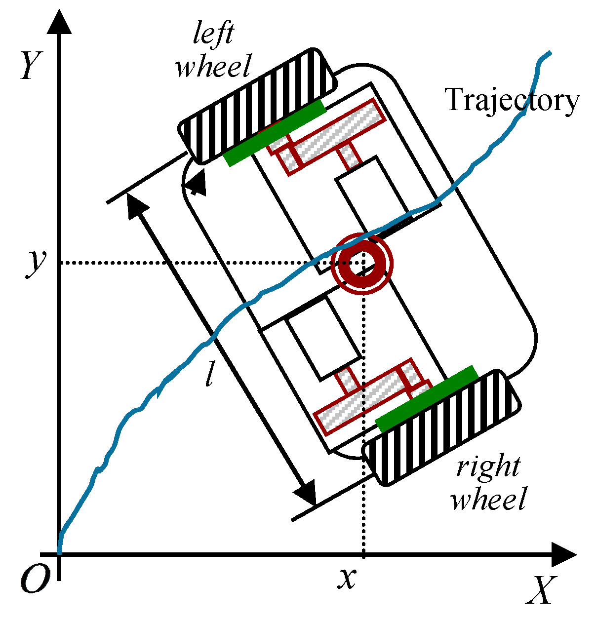
3. Kinematic Modeling
Figure 1 shows the structure of a typical two-wheeled WMR with a differential drive mechanism. In this schematic, the driving wheels are used to supply required power of the platform. Considering the fact that the two driving wheels roll and do not slip, we have:
where (
) is the coordinate of the robot center of mass,
and
are the velocities of this center along
and
axes, respectively.
denotes the orientation of the robot with respect to the initial position at the start point of the motion, and
is its derivatives with respect to time.
and
are the nominal diameters of the right and left wheels, respectively. Angular velocities of the right and left wheels are denoted by
and
, respectively. The nominal distance between the two driving wheels is represented by
.
In addition, considering the fact that the mobile robot cannot move in the lateral direction, the third equation is obtained as follows:
4. Proposed Odometry Technique
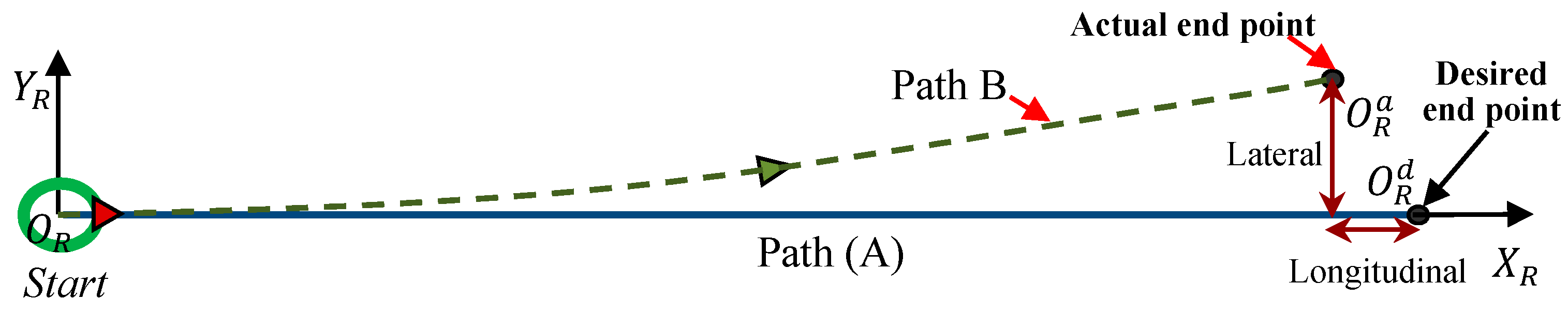
Figure 2 shows the test trajectory and needed parameters. As observed, the robot is programmed to travel along the path A, while regardless of the error sources, the robot follows path B [
2,
3]. The positional error has two components: lateral error and longitudinal error. Therefore, two corrective indices are defined to correct these two errors: lateral corrective factor and longitudinal corrective factor. The lateral corrective factor
is applied to kinematic equations of robot to ensure that the robot stays along the desired trajectory. This factor presents the ratio of two angular velocities read from the encoders (the displacement over time) and is defined as below [
2]:
where,
To compensate the longitudinal position error, the longitudinal corrective factor (
) is defined as follows [
2]:
where
is the length of trajectory A.
and
are averages of the robot longitudinal and lateral errors over
number of trial runs [
6].
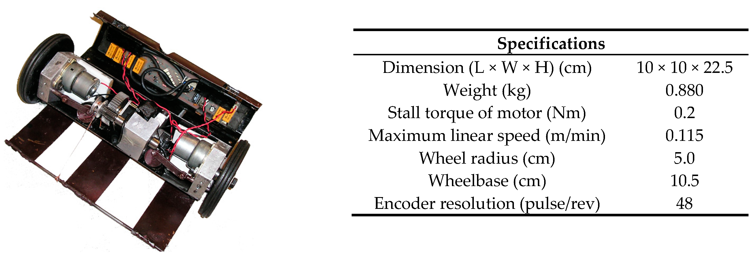
5. Prototype WMR
This section describes a prototype mobile robots with a variety of components to examine the performance of the described benchmark techniques. Detailed description of the robot are given in [
2]. The Jumper (two-wheeled) consists of two driving wheels, two stepping motors with gear boxes, two ultrasonic sensors and a wireless camera to detect the obstacles (
Figure 3). Specifications of the robot are also shown in
Figure 3.
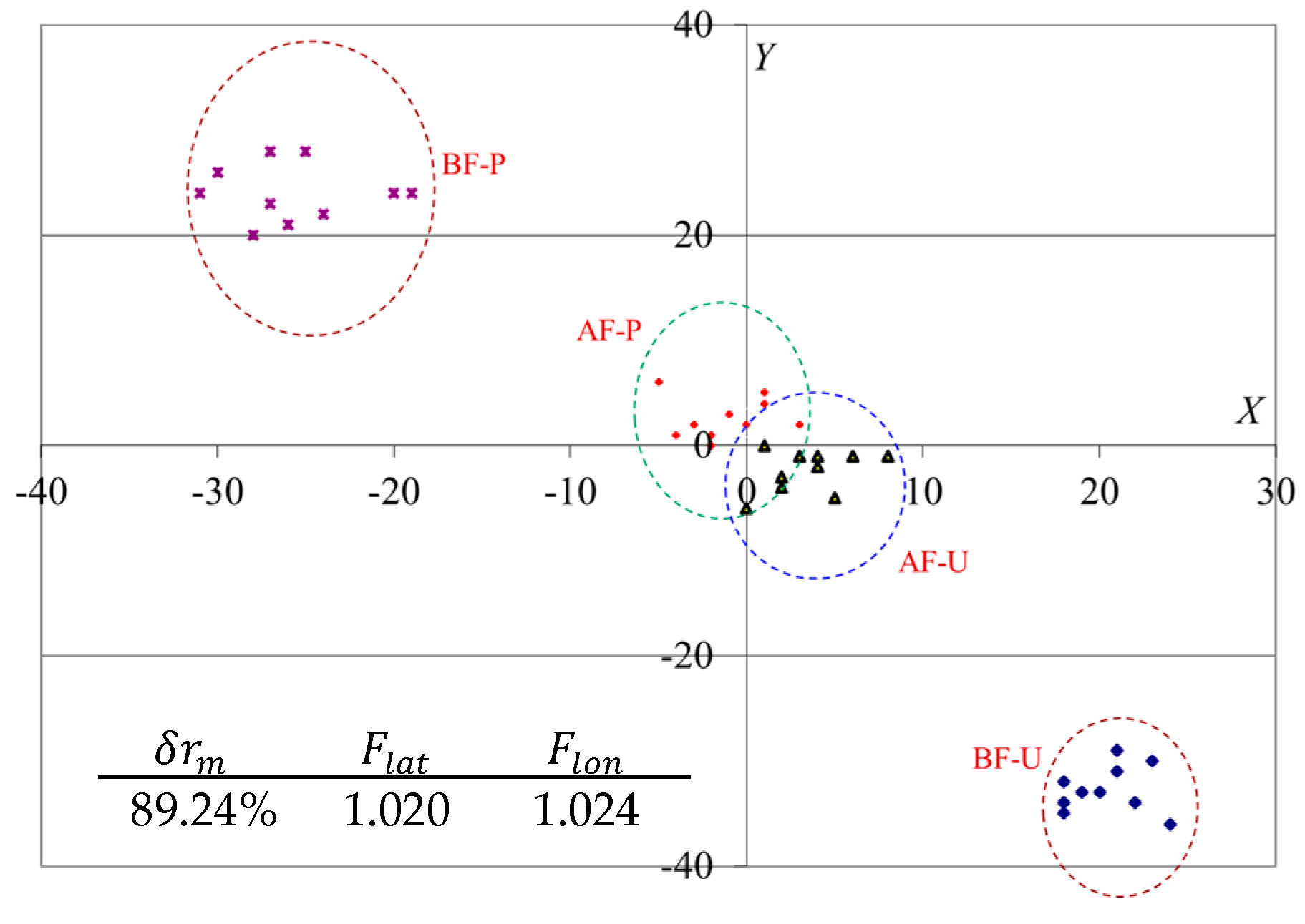
6. Results
The metric used to facilitate the comparison is the radial error (
) as [
2]:
where
and
are the longitudinal and lateral errors (
and
in
Figure 2). Effectiveness of each method is then measured by comparing the mean error improvement index (
):
In (8), and are the mean values of radial errors before and after calibration, respectively.
Figure 4 shows the position errors before and after calibration using the proposed method for the jumper robot. As seen, the motions of the robot were corrected with the method, i.e., the errors converged to the center of coordinate system (zero positional error). Statistical measures, to show the performance of the robot motion, are also reported in
Figure 4.
7. Conclusions
Odometry errors in WMRs with differential drives are inevitable as they originates from hard to completely avoid imperfections such as unequal wheels diameters, misalignment at joints, backlash, slippage in encoder pulses and much more. The focus of this study was on introducing an odometry- based technique to correct the systematic errors of WMRs. A prototype differential drive mobile robot was constructed to evaluate the effectiveness of the developed method. Experimental results showed that the method was able to reduce the systematic errors by at least 83%.

