1. Introduction
Increased devices operating frequency and reduced size are actual challenges in the field of electroacoustic devices development. Piezoelectric resonators showing small size and high Q at GHz frequency range can be fabricated by exploiting the diamond and piezoelectric AlN film technology. The main objective of this paper consists in the modelling study of the Lamb modes propagation in the thin suspended composite membranes including an AlN layer 3.6 μm thick on top of a diamond suspended membrane 10 μm thick. Disperse software was used to calculate the phase and group velocity dispersion curves of the Lamb modes in diamond/AlN structures. The zero group velocity (ZGV) resonant conditions, i.e., the frequencies where the mode group velocity vanishes while the phase velocity remains finite, were found. Exact numerical calculations were performed to estimate the electroacoustic coupling efficiency, K
2, of the ZGV points. By means of FEM analysis, the propagation of acoustic Lamb waves in the AlN/diamond layered structure has been investigated and the elastic displacement fields within the composite plate were calculated. The ZGV points of a Lamb mode device are associated with an intrinsic energy localization under the metal electrodes: this fact enables the design of acoustic micro-resonators employing only one interdigital transducer (IDT) and no reflectors, thus reducing both the device size and the technological complexity [
1]. At the ZGV points, the mode energy is locally trapped in the source area thus these modes are expected to be highly sensitive to the plate thickness and mechanical properties changes. Thin film bulk acoustic resonators (TFBARs) based on c-axis oriented and 45° c-axis tilted AlN film on diamond was simulated that are based on the propagation of longitudinally and in plane-shear horizontally polarized modes, respectively; the former is suitable for sensing in gaseous environment while the latter is suitable for liquid sensing applications. This paper provides a simulation study of a monolithically integrated smart system suitable for applications in the frequency control and sensing fields. Since the resonators are fabricated using standard microelectronics techniques, and in particular the thin piezoelectric film technology, further addition of integrated circuits on the same silicon wafer can provide the design and fabrication of “smart” devices: the ZGV resonator can work as a frequency control element [
2] as well as gas sensor, while the TFBAR can work as a gas and liquid sensor, depending on the AlN c-axis orientation. Furthermore, other devices can be implemented on the same silicon wafer to conduct signal processing, calibration, and output buffering.
2. Lamb Modes in Diamond/AlN Composite Plate
The propagation of quasi-Lamb waves along a diamond/AlN thin suspended composite membrane is here investigated. The membrane consists of a piezoelectric AlN layer, 3.6 μm thick, on top of a diamond layer 10 μm thick. The quasi-Lamb waves propagation can be excited and detected by use of interdigitated transducers (IDTs), as for the surface acoustic waves (SAWs). The wavelength of the acoustic wave, λ, is set by the pitch of the IDT. In the present simulations, the IDTs metallization ratio is supposed to be equal to 1.
Figure 1 shows the schematic of the device including the array of electrodes on top of the piezoelectric AlN layer.
This device can be obtained by standard technological processes, such as the backside Si/diamond/AlN micro-machining process for the fabrication of suspended membranes. In this case the diamond layer plays the role of a back-etching stop layer, allowing the release of a diamond/AlN suspended membrane. The phase and group velocity (v
ph and v
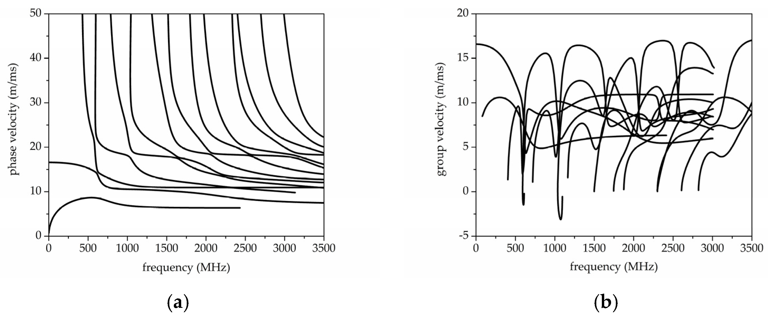
gr) dispersion curves of the Lamb-like modes travelling along the diamond/AlN composite plate were calculated and plotted in
Figure 2a,b vs. the frequency f = v
ph/λ.
The diamond and AlN material constants used to perform the phase and group velocity dispersion curved by the Disperse software [
3] are listed in
Table 1 [
4]; both materials are assumed to be lossless. The distinction between symmetric and antisymmetric Lamb modes in
Figure 2a,b is somewhat artificial for a composite plate as the symmetry with respect to the mid plane of the plate is lost in the plate under study. Thus the quasi-Lamb mode dispersion curves can be only generically distinguished by a number in the order in which the modes appear along the frequency axis [
5].
Some branches of the group velocity dispersion curves, corresponding to the ‘‘backward-wave’’ propagation, occur in the negative-slope region where group velocity and phase velocity have opposite signs. For negative group velocities, the direction of propagation of wave energy and that of wave phase are opposite. Some Lamb wave resonances, referred to as the ZGV resonances, occur at the frequency values at which some high order modes exhibit null group velocity and finite phase velocity. FEM analysis was performed using COMSOL Multiphysics to explore the field shape of the ZGV points in the composite waveguide. Initially, the plate-guided modes were identified by frequency-response analysis of a 2D composite plate with the IDT assumed to have 5 finger pairs, as shown in
Figure 1. For simplicity, the presence of the silicon frame was not accounted in the simulations and the total length of composite plate is 20·λ. Traction free boundary conditions were selected for the top and bottom sides of the composite plate, while continuity boundary condition were selected for the right and left end sides of the waveguide. The geometrical parameters of the ZGV structures used in the simulation are given in
Table 2.
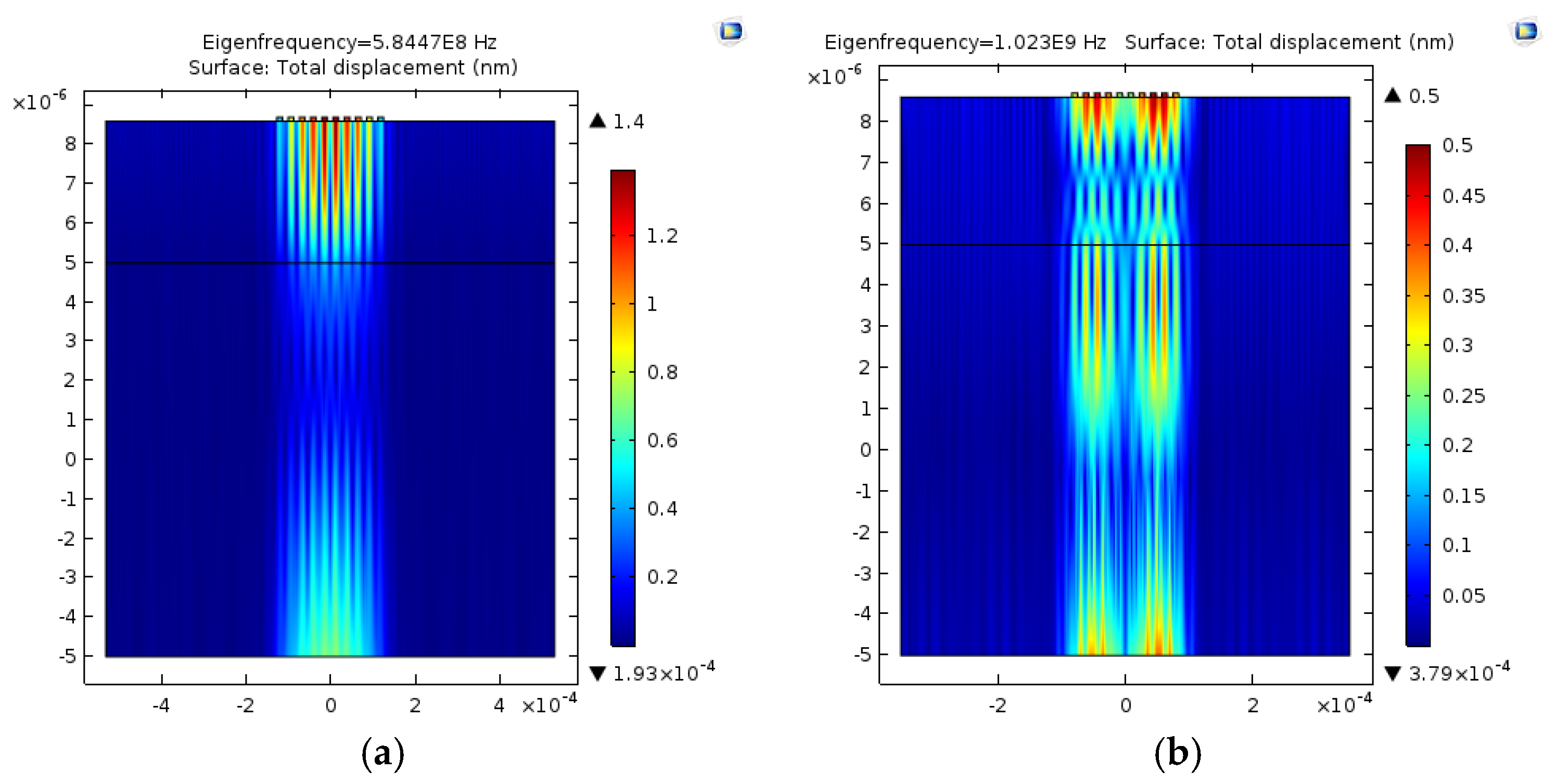
As an example,
Figure 3a,b show the field profile of the ZGV points referred to the modes 3 and 6 (hereafter named ZGV3 and ZGV6). The total displacements of these modes were determined by an eigenfrequency 2D FEM analysis with applied boundary conditions: the color bar is representative of the relative particle displacement. As it can be seen, the acoustic field of the ZGV3 and ZGV6 modes are localized in the active region of dimension approximately equal to 5 wavelengths.
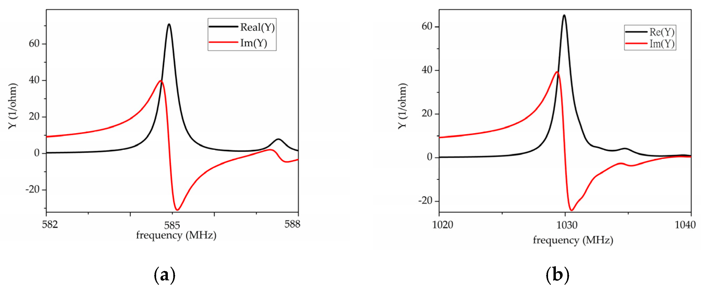
The real and the imaginary part of the ZGV3 and ZGV6 resonators admittance were calculated and the results are shown in
Figure 4a,b. The electroacoustic coupling efficiency (K
2) and the Q factor were calculated from the formula:
and
, being f
s, f
p, f
r and δ the series, parallel, and resonant frequencies, and the -3dB bandwidth; the following vales were calculated, K
2 = 0.17% and Q = 1462 for ZGV3, K
2 = 0.27% and Q = 844 for ZGV6.
3. Diamond/AlN-Based TFBARs
A thin film bulk acoustic resonator (TFBAR) was supposed to be monolithically implemented on the same AlN/diamond suspended membrane consisting of a pair of metal electrodes (Pt 0.1 μm thick, and 350 μm × 350 μm the area) sandwiching the piezoelectric thin film, with AlN and diamond layers 3.6 and 10 μm thick. The TFBAR is based on the propagation of longitudinal bulk acoustic waves (LBAWs) along the composite plate as the AlN layer is supposed to be c-axis oriented normal to the diamond layer surface. These devices are utilized in telecommunications field, as well as for sensors operating in air but not in liquid as the LBAWs, as opposed to the shear horizontal bulk waves (SHBAWs), are very much damped by acoustic emission into the liquid. TFBARs based on the propagation of mixed LBAWs and SHBAWs can be obtained with AlN film showing c-axis tilted by an angle ϑ with respect to the film normal [
6]. A pure shear and longitudinal mode excitation can be obtained for specific ϑ values as the K
2 of both the longitudinal and shear modes is affected by ϑ. A Matlab routine was written to numerically calculate the velocity
v and K
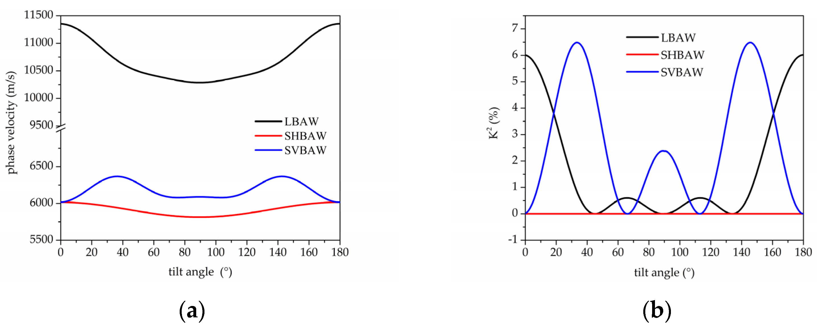
2 of the LBAW, SHBAW and SVBAW (shear vertical BAW) propagating along AlN substrate for different c-axis tilt angle ϑ, and the results are shown in
Figure 5a,b.
A ϑ ranging from 20° to 45° provides sufficiently high values of the K2 of the shear mode; a single pure shear mode propagates at ϑ = 46.1° and 90°, and a pure longitudinal mode propagates at ϑ=0° and 67.1°; at about 19°, the longitudinal and shear BAWs have the same K2 (about 3.8%). Compared with the longitudinal wave K2, the SHBAW has higher coupling (up to 6.5%) thus it provides a better choice for the design of higher bandwidth filter. Thus an easy discrimination of the two modes can be obtained by choosing ϑ = 45° as only the shear mode is electrically coupled.
FEM has been performed by Comsol Multiphyics software to model the admittance Y vs. frequency curves and to investigate the resonators K
2 (the AlN mechanical loss tanδ = 0.002 was accounted for).
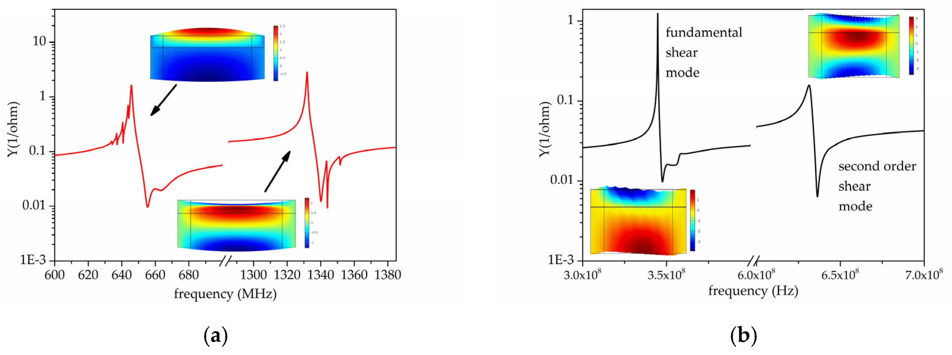
Figure 6a shows the absolute value of the admittance vs. frequency curves of the first two longitudinal resonances of the FBAR based on c-AlN/diamond: the resonant frequencies correspond to f
p = 650 and 1350 MHz, and K
2 = 3.71 and 1.54% respectively.
Figure 6b shows the absolute value of the admittance Y vs. frequency curves for the first two shear resonances of the FBAR based on 45°-tilted AlN/diamond; the resonant frequencies correspond to f
p = 345 and 633 MHz, and K
2 = 2.08 and 1.91%, respectively. The K
2 values were estimated from the eigenfrequencies of each mode, with and without the piezoelectricity effect. The two insets in
Figure 6 also show the longitudinal and shear modes displacement field.

