Proceeding Paper

An Experimental Study on the Propagation of the Pressure Fluctuations Induced in a Tube Array under Forced Vibration †

Energy Department, Oviedo University, 33205 Oviedo, Spain
*
Author to whom correspondence should be addressed.
Presented at the 2nd International Research Conference on Sustainable Energy, Engineering, Materials and Environment (IRCSEEME), Mieres, Spain, 25–27 July 2018.
Proceedings 2018, 2(23), 1501; https://doi.org/10.3390/proceedings2231501
Published: 7 November 2018

Abstract

:
Tube arrays subject to cross flow may exhibit large amplitude self-excited vibrations referred to as Fluidelastic Instability (FEI). Due to its potential for damaging the equipment in an extremely sort operational time, FEI is considered the most destructive mechanism within the flow induced vibration phenomena and has been extensively analysed in the literature in the past, however, the underlying mechanism for FEI onset remains unclear. A number of models, based on very different assumptions about the fluidmechal phenomenon has been developed with the common conclusion that the key factor for stability onset is in the relationship between tube motion and flow perturbation in terms of amplitude and phase. In the present study an experimental approach in a water channel especially designed and developed by the authors for the present investigation is proposed. The empirical set-up, consisting in a tube array in which one tube is forced to vibrate while pressure fluctuations due to is motion are monitored in several points of the array, allows to correlate tube motion and pressure perturbations. The FFT postprocess of those signals allows for the study of the perturbations propagation pattern and indeed in the understanding of the FEI phenomenon. Finally present experimental results will allow for the validation, adjust and improvement of a CFD model previously developed by authors.

1. Introduction

The development of self-excited vibrations in cylinder arrays subject to cross-flow such as in shell-and-tube heat exchangers, usually referred to as fluidelastic instability (FEI) has been described basically by three theoretical frameworks: the “wavy-wall” model (Lever and Weaver, 1986) [1,2]; the quasi-static model (Connors, 1970) [3]; and the quasi-steady model (Price and Paı¨doussis, 1984) [4]. There are also a number of empirical models and numerical simulations of using Large Eddy Simulation, Reynolds Averaged Navier Stokes (de Pedro et al., 2016) [5]. and vortex methods. A review of the various models can be found in Price (1995) [6]. FEI, can be triggered by either a fluid damping or a fluid stiffness controlled mechanism [7,8]. The latter requires several degrees of freedom, but the fluid-damping mechanism only requires motion of one single cylinder in one direction, with lower critical flow velocity for the oscillations in the transverse direction than streamwise. The phenomenon is attributed to the phase lag between the instantaneous fluid forces applied on the tubes and their position during each oscillation, though different origins have been proposed to explain that lag. Lever and Weaver [8,9] used the fluid inertia concept to build a quasi-analytical model in which the main flow passes through the array along wavy channels or streamtubes. Paidoussis and Price [8] associate that effect to the delay in the reorganization of the flow in the wake. Granger and Paidoussis [9] describe it as a memory effect due to the diffusion of thin vorticity layers from the oscillating tube surface into its boundary layer, to be finally convected downstream.
There have been few studies intended to verify how disturbances lag and decay while they are transmitted in the flow, which is key in Lever and Weaver’s model. The most notorious experimental study corresponded to Khalifa et al. [10], who observed that velocity fluctuations originated near the flow separation region behind the oscillating tube. And propagated both up and downstream with a speed proportional to the gap velocity and decaying amplitude while separating from the origin.
This paper presents a novel experimental study on the fluctuations induced in the flow by a single vibrating tube in a parallel triangular array with P/d = 1.57, very similar to the array tested by Khalifa et al. [10]. Pressure fluctuation observed at several points of the array due to the forced motion in the transverse direction of one single in the middle of the array where measured in several experimental campaigns. After each series of tests, pressure fluctuations recorded were FFT processed allowing to correlate motion and the generated fluctuations in amplitude and phase along the channels of the array.

2. Experimental Set-Up

Experimental set-up consisted in tube array subject to cross flow in a specifically designed water channel, geometry of the tube array is shown in Figure 1 while the overall set-up for the water channel producing the water cross-flow stream can be seen in Figure 2.
In the middle of the array one single tube is forced to vibrate transversally by means of an eccentric rotating mechanism connected to the top of tube TV while in the top of tubes T1, T2, T3 and T4 (see Figure 1) pressure transducers are located in order to correlate tube motion and pressure perturbations. Figure 3 shows configuration for both tube motion mechanism and pressure transducers mounting.

3. Experimental Procedure and Signal Processing

Series of experimental measurements at different reduced velocities for the cross-flow were carried out and both tube motion and pressure fluctuations recorded and FFT post processed in order to correlate their interaction in terms of amplitude and phase. Typical spectra for accelerometers and pressure transducers is shown in Figure 4.

4. Results

Figure 5 show some results obtained after the mentioned FFT post-process, as can be seen in Figure 5a with the described mechanism the resulting motion takes places principally in the transverse direction as was the objective for the present study. Regarding the amplitude of pressure perturbations it is observed that amplitude in the cylinder downstream the vibrating tube is higher and also phase is closer to tube motion one compared to results of the tube upstream, this is attributed to the effect of the own cross flow, as perturbations that are being transmitted through the water stream also are dragged downstream for it. As expected, pressure perturbations are lower for higher cross flow reduced velocities, as tube velocity generating those perturbations is getting less important in comparison to cross flow velocity.

5. Conclusions

A novel experimental study on the fluctuations induced in the flow by a single vibrating tube in a parallel triangular array with P/d = 1.57 has been presented. Pressure fluctuation where measured in several experimental campaigns. Experimental results were FFT processed allowing to correlate motion and fluctuations in terms of amplitude and phase.
Specific conclusions obtained in the present study can be summarized as follows:
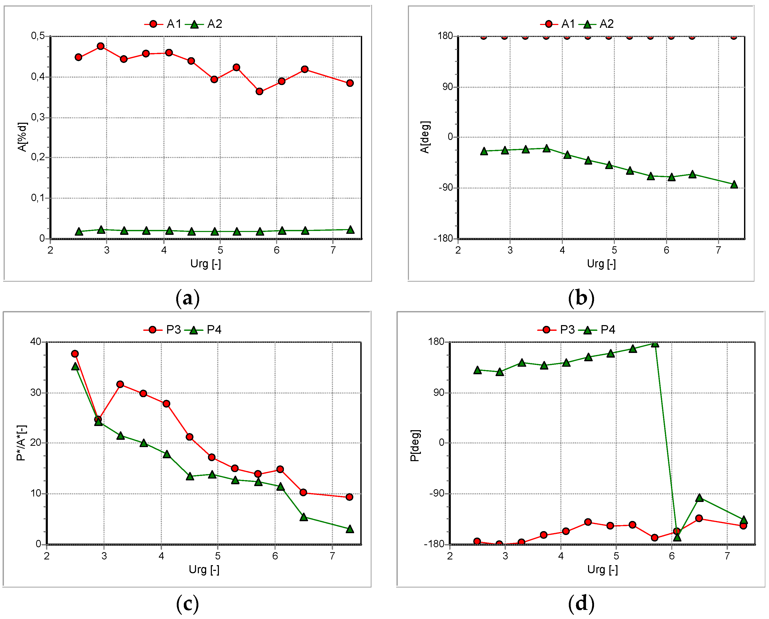
  • Amplitude of pressure perturbations in the cylinder downstream the vibrating tube is higher and also phase is closer to tube motion one compared to results of the tube upstream, as perturbations that are being transmitted through the water stream also are dragged downstream for it.
  • Pressure perturbations are lower for higher cross flow reduced velocities, as tube velocity generating those perturbations is getting less important in comparison to cross flow velocity.
  • Although the present work is still an ongoing study, results obtained with the experimental methodology developed are promising, future experimental campaigns will be undertaken to extract more information of the empirical test and contrast results with CFD calculations obtained with the previous numerical model [5].

Author Contributions

L.T., B.d.P. and J.P. conceived and designed the experiments; L.T. performed the experiments; J.P. and B.d.P. analyzed the data; G.L. contributed theoretical analysis tools; B.d.P. wrote the paper.

Acknowledgments

The authors gratefully acknowledge the financial support received from the Spanish Ministry of Economy and Competitiveness (project MCE-DPI-2012-36464) as well as the Ph.D. grant BP-12054 awarded to Beatriz de Pedro by the Principality of Asturias Government.

Conflicts of Interest

The founding sponsors had no role in the design of the study; in the collection, analyses, or interpretation of data; in the writing of the manuscript, and in the decision to publish the results.

References

  1. Lever, J.; Weaver, D. On the stability of heat exchanger tube bundles. Part I: Modified theoretical model. J. Sound Vib. 1986, 107, 375–392. [Google Scholar] [CrossRef]
  2. Lever, J.; Weaver, D. On the stability of heat exchanger tube bundles. Part II: Numerical results and comparison with experiments. J. Sound Vib. 1986, 107, 393–410. [Google Scholar] [CrossRef]
  3. Connors, H.J. Fluidelastic vibration of tube arrays excited by cross flow. In Flow-Induced Vibration in Heat Exchangers; Reiff, D.D., Ed.; ASME: New York, NY, USA, 1970; pp. 42–56. [Google Scholar]
  4. Price, S.J.; Paidoussis, M.P. An improved mathematical model for the stability of cylinder rows subject to cross-flow. J. Sound Vib. 1984, 97, 615–640. [Google Scholar] [CrossRef]
  5. de Pedro, B.; Parrondo, J.; Meskell, C.; Fernández-Oro, J. CFD modelling of the cross-flow through normal triangular tube arrays with one tube undergoing forced vibrations or fluidelastic instability. J. Fluids Struct. 2016, 64, 67–86. [Google Scholar] [CrossRef]
  6. Price, S.J. A review of theoretical models for fluidelastic instability of cylinder arrays in cross-flow. J. Fluids Struct. 1995, 9, 463–518. [Google Scholar] [CrossRef]
  7. Chen, S.S. Instability mechanisms and stability criteria of a group of circular cylinders subjected to cross-flow, part II: Numerical results and discussion. J. Vib. Acoust. Stress Reliab. Des. 1983, 105, 253–260. [Google Scholar] [CrossRef]
  8. Paidoussis, M.P.; Price, S.J. The mechanisms underlying flow-induced instabilities of cylinder arrays in cross-flow. J. Fluid Mech. 1988, 187, 45–59. [Google Scholar] [CrossRef]
  9. Granger, S.; Paidoussis, M. An improvement to the quasi-steady model with application to cross-flow-induced vibration of tube arrays. J. Fluid Mech. 1996, 320, 163–184. [Google Scholar] [CrossRef]
  10. Khalifa, A.; Weaver, D.; Ziada, S. An experimental study of flow-induced vibration and the associated flow perturbations in a parallel triangular tube array. J. Press. Vessel Technol. 2013, 135, 030904. [Google Scholar] [CrossRef]
Figure 1. Parallel triangular tube array configuration and geometrical parameters used in the study.
Proceedings 02 01501 g001
Figure 2. Hydraulic channel experimental overall configuration.
Proceedings 02 01501 g002
Figure 3. Tubes experimental set up (a) Forced vibration mechanism for the vibrating tube (b) pressure transducers location in the monitored tubes.
Proceedings 02 01501 g003
Figure 4. Typical spectra observed in accelerometers and pressure transducers for tubes at different positions in the stream channel. (a) Vibration amplitude in X and Y coordinates for de oscillating tube; (b) Pressure perturbations amplitude at different tubes in the array.
Proceedings 02 01501 g004
Figure 5. Amplitude and phase measurements observed in accelerometers and pressure transducers respectively: (a) Amplitude of vibration in Y = A1 and X = A2 coordinates; (b) Phases for tube motion in Y = A1 and X = A2 coordinates; (c) Amplitude of pressure perturbations in P4 = T2 and P3 = T3 locations in the array (see Figure 1); (d) Phase of pressure perturbations in P4 = T2 and P3 = T3 locations in the array (see Figure 1).
Proceedings 02 01501 g005
Publisher’s Note: MDPI stays neutral with regard to jurisdictional claims in published maps and institutional affiliations.

