Proceeding Paper

Structural Properties Ni20Cr10Al2Y Coatings for Geothermal Conditions †

1
Metav-R&D, 31 C.A. Rosetti St., Bucharest 020011, Romania
2
Tehnoid Com Ltd., 48 Baritiu Str., Bucharest 011259, Romania
3
Engineering and Management of Metallic Material.s Production Department, University “Politehnica” Bucharest, 313 Splaiul Independentei, Bucharest 060042, Romania
*
Author to whom correspondence should be addressed.
Presented at the 2nd International Research Conference on Sustainable Energy, Engineering, Materials and Environment (IRCSEEME), Mieres, Spain, 25–27 September 2018.
Proceedings 2018, 2(23), 1434; https://doi.org/10.3390/proceedings2231434
Published: 8 November 2018

Abstract

:
The chromium carbide hard phases powders are used for the high velocity oxygen fuel (HVOF) coating technique. This paper investigates samples coated with Ni20Cr10Al2Y on carbon steel plates. The coatings were designed to improve the erosion corrosion properties of carbon steel. The specific agglomerated nanosized Cr3C2 particles on the coated layer provide new physical, mechanical and chemical properties. The multilayer composite technique could be successfully used to protect turbine working in geothermal system. The samples were investigated using nanoindentation to determine the coated samples mechanical properties. The experimental procedure involved obtaining X-ray diffraction patterns of the specimens, micro mechanical tests and SEM investigation to provide detailed information about adhesion of protective layers and morphological modifications.

1. Introduction

Geothermal sources are very aggressive natural environments in terms of corrosion and erosion. High temperature and pressure conditions, as well as corrosive salts, represent a major threat to the integrity of the various components of geothermal power plants. Carbon steel which has poor resistance to corrosion, is commonly used in geothermal application because of its low cost and availability and weld ability. The High Velocity Oxygen Fuel Deposition (HVOF) process has emerged as a suitable and effective surface engineering technology and is widely used to apply wear, erosion and corrosion protective coatings [1,2,3] in various kinds of industrial applications. Cr3C2-based coatings have been applied to a wide range of industrial components. Structural components Cr3C2–NiCr coatings offer greater corrosion and oxidation resistance, have a higher melting point and maintain high hardness, good strength and wear resistance up to a maximum operating temperature of 900 °C. The corrosion resistance is provided by NiCr matrix while the wear resistance is mainly due to the carbide ceramic phase [4,5,6]. Complex powder Nickel based composites coatings show good high-temperature wear and corrosion resistance. The good resistance is given by the addition of some percent of Cr and Al elements to the powders. Better performances in oxidizing environments would be achieved with systems based on NiCrAlY type alloys, which are accordingly employed to prevent oxidation and hot corrosion. Pure NiCrAlY is unsuitable for direct tribological applications due to its reduced hardness. In this case the manufacturing of complex composite coatings based on NiCrAlY alloys reinforced by cermet agglomerate nanostructurate powders of Cr3C2 appears as a viable solution in order to couple the oxidation resistance of the metal matrix to the hardness and chemical stability of the ceramic phase [6,7]. In thermal HVOF technology the Cr3C2-NiCr cermet coatings have been extensively used to mitigate abrasive and erosive wear at high temperatures up to 850–900 °C. Researchers agree that carbide-based coatings provide excellent erosion protection but disagree on the optimum amount of carbide for maximum erosion resistance [8,9]. The combination 75Cr3C2–25NiCr coatings are primarily designed for wear applications either at elevated temperatures or in corrosive environments. In most of the cited references, such NiCrAlY composites were deposited by thermal spray processes, their main advantages include high productivity and flexible coupling of a large variety of coating and substrate materials [10]. The field literature [10,11] mentioned that adherence of the sprayed particles occurs generally by a mechanical adherence, simultaneously with the attachment of particles during their cooling and contracting phase. This papers aims to investigate the NiCrAlY coating on a carbon steel substrate, sprayed using HVOF process. The investigation was performed in terms in coating characterization to see if the obtained material could be an option for using in geothermal environment.

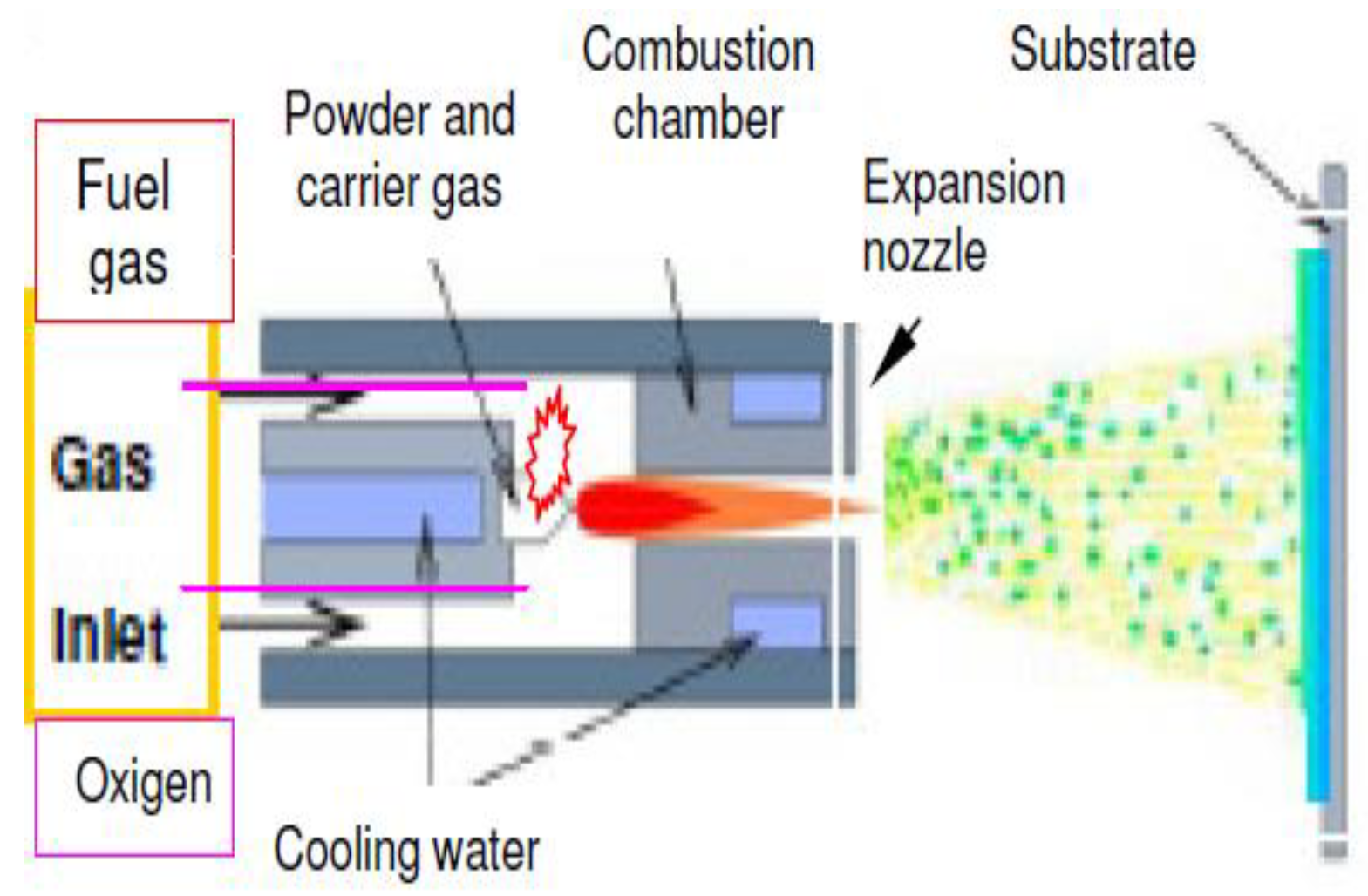
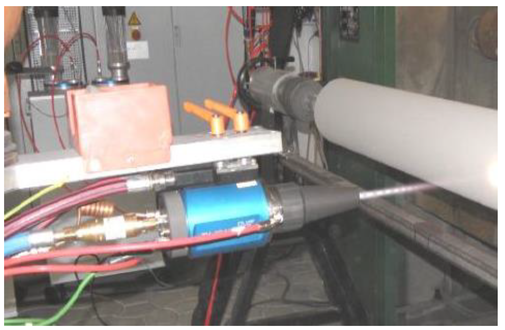
2. Materials and Methods

For the protection of carbon steel surfaces using multi-composite materials, HVOF has emerged as a suitable technique to obtain apply wear, abradable and corrosion protective coatings for metallic components. Plasma coatings are relatively heterogeneous, anisotropic, micro porous and contain micro cracks. The characterization of the coatings was conducted for producing powder used NiCrAlY alloy, whose characteristics are included in Table 1. The apparent density of the powder was measured according to ASTM B212 and the flow rate was measured using ASTM B964. As a substrate for coatings samples there were used hot-rolled carbon steel standard EN 10025-2:2004 (Table 1).
For the sizing determination of the powder, we used a sizing machine type Retsch AS200. The used sizing method was volumetric dry sieving. The machine worked at a vibration powder of 45 min. The complex composite coatings manufacturing, based on NiCrAlY alloys reinforced by refractory agglomerate nanostructurate powders of Cr3C2-NiCr appears as a viable solution in order to couple the oxidation resistance of the metal matrix, to the hardness and chemical stability of the ceramic phase. In the nanocrystalline state, due to the small grain size, some of the physical properties show no manifestation of anisotropy. Fine Cr3C2 particles are incorporated into the Ni20Cr base metallic matrix using the ball milling operations [11,12]. The powders particles were homogenizing two hour in a high velocity ball milling Retsch type, using an argon protective atmosphere and stainless steel vial and balls. The addition of Cr3C2 to HVOF spraying powders, improves the hardness and elastic modulus with lowering the cracking susceptibility and reducing the number of pores. The parameter of HVOF process deposition regarding gas and flows pressures are presented in Table 2.
Pulsed detonation system (Figure 1), which can provide high-velocity gas jet with significantly lower heat flux, is an alternative to plasma technologies. The high power of the gas jet in pulsed systems, has a dominating kinetic component. The powder in these jets acquires high kinetic energy and this can form a lamella coating structure on a hard substrate. Figure 2 presents the HVOF supersonic jet (2000 m/s) and the formation of stationary shock waves in plasma process deposition of layers by Diamond Jet Gun.
The spraying distance is an important parameter to be considered for tuning the processing conditions and thus to maintain or even improve the adhesion of the coatings. For the experiment presented in this paper we used the spraying distance of 250 mm based on the authors past experience in composite deposition. The experimental procedure for the structural prosperities investigation involved obtaining X-ray diffraction patterns of the specimens-XRD, analyses by X-ray Diffractometer Panalytical X’Pert Pro MPD with Cu Kα radiation. Scanning Electron Microscopy analysis (SEM) and energy dispersive spectroscopy (EDX), was used to analyze the interface diffusion behavior of the bond coat elements and to provide detailed information about adhesion of protective layers and morphological modifications. SEM has been used to study all aspects of particles morphology, including size, shape, surface topography, coating characteristics. The obtained samples have been SEM analyzed using a Quanta Inspect F scanning electron microscope equipped with a 1.2 nm resolution field emission gun (FEG) and a 130 eV MnK resolution X-ray energy. On the composite HVOF layers deposition, there were observed new phases, microstructure and texture, which results in varied physical properties including hardness, strength, toughness, ductility, and wear resistance. In this application, the Nano-Mechanical Tester type CSM Instrument Identation is used to measure the mechanical properties of a multi-phase metallurgical sample. The Nano Indenter enables users to measure Young’s modulus and hardness in compliance with ISO 14577. The capabilities of the Nano Platform can be extended to facilitate specific testing, expanded load capacity up to 10 N. Tribological characterization of the samples was to determine roughness (Ra), friction coefficient and wear rates, with a standard tribometer pin on disk, equipped with rotary module (CSM Instruments, Switzerland, according to SR EN ISO 3274:2001, SR EN ISO 4288:2002, DIN 50324 and ASTM G 133-95 [15,16,17,18].

3. Results and Discussion

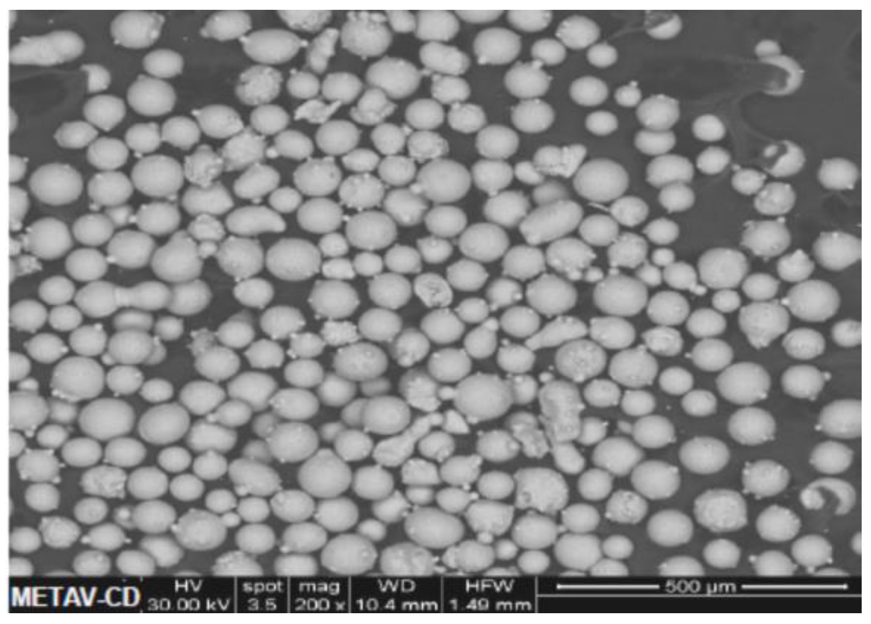
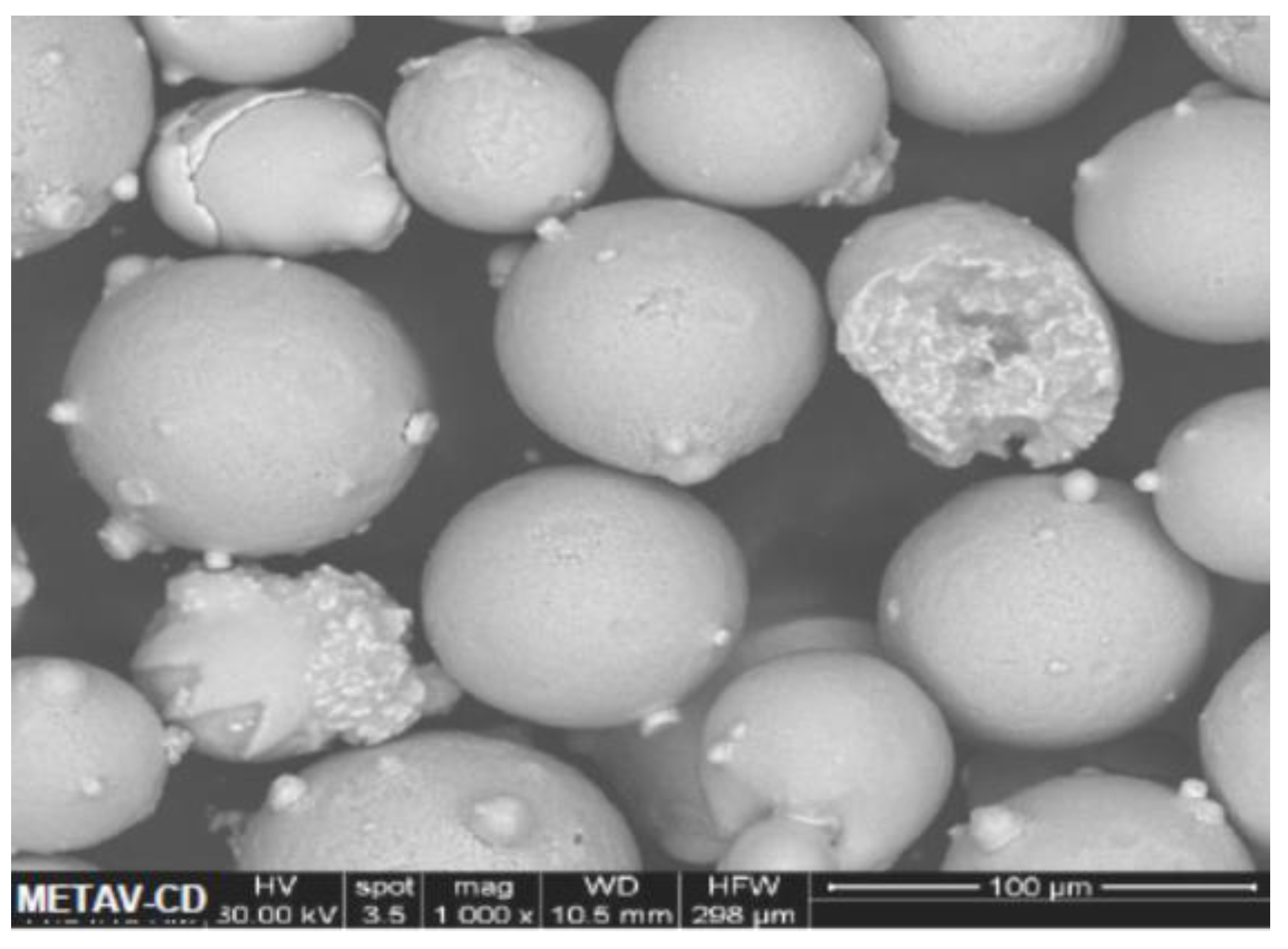
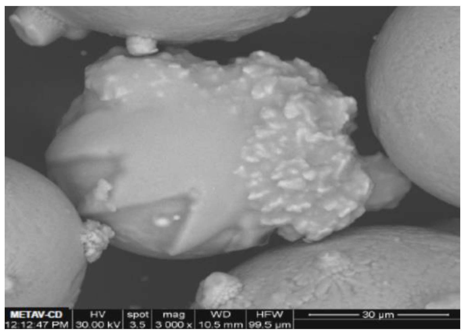
3.1. Initial Powder Characterization

The complex powders used for coating were characterized in order to determine the characteristics necessary for coating application using HVOF procedure. The investigation revealed that the powders have an adequate flowing rate (As shown in Table 3 and Figure 3) as well as a size distribution allowing the HVOF process. A determination of the flow rate of a powder is important in high-volume manufacturing which depends on the rapid, uniform, and consistent filling of the cavity. Poor flow characteristics (Figure 3) cause no uniform feeding and difficulties in ensuring HVOF processing.
Flow characteristics are dependent on several variables including particle shape and size, type of material, environmental factors, and weight of the bulk. The presence of oxide films on powder particle surfaces modify the friction between particles and increase flow rate and have a major influence on the theoretical density and on other characteristics, such as adhesive and cohesive surface properties [13,14]. Nickel based powders has excellent flow ability and feed through the system.
The shape of powder affects the flow rate; as a result, very low deposition rates for angular powders are commonly observed. The spheroidization is detected and we can see a significant increase of equivalent diameter. The relative occurrence of the dimensions has been found to depend of the distributed of elemental powder on the particle surfaces. The powder morphology is predominantly spherical particles (Figure 4). In SEM image the particle shape and surface topography can be observed (Figure 5) a representative sample of the particle size distribution.
Figure 5 reveals SEM micrograph displaying and the typical rounded shape of the composites powder with a particle diameter around 50 µm. There were also smaller particles and satellite particles adhered to it (Figure 6). The finer grades of powder require higher pressures and small molten metal streams of complex mixture 20%Cr10%Al2%Y. The EDS qualitative studies show a characteristic spectrum which indicates the presence of chemical elements present in the powders and the relative percentage. An elemental EDS mapping was also performed to determine the distribution of Ni,Cr,Al in them. Figure 7 show the results of this mapping and also that the alloying elements NiCrAl are homogeneously distributed. In the EDS spectrum (Figure 8) was observed with low intensity and broadened width, indicating that Y2O3 particles into the complex-powders samples.

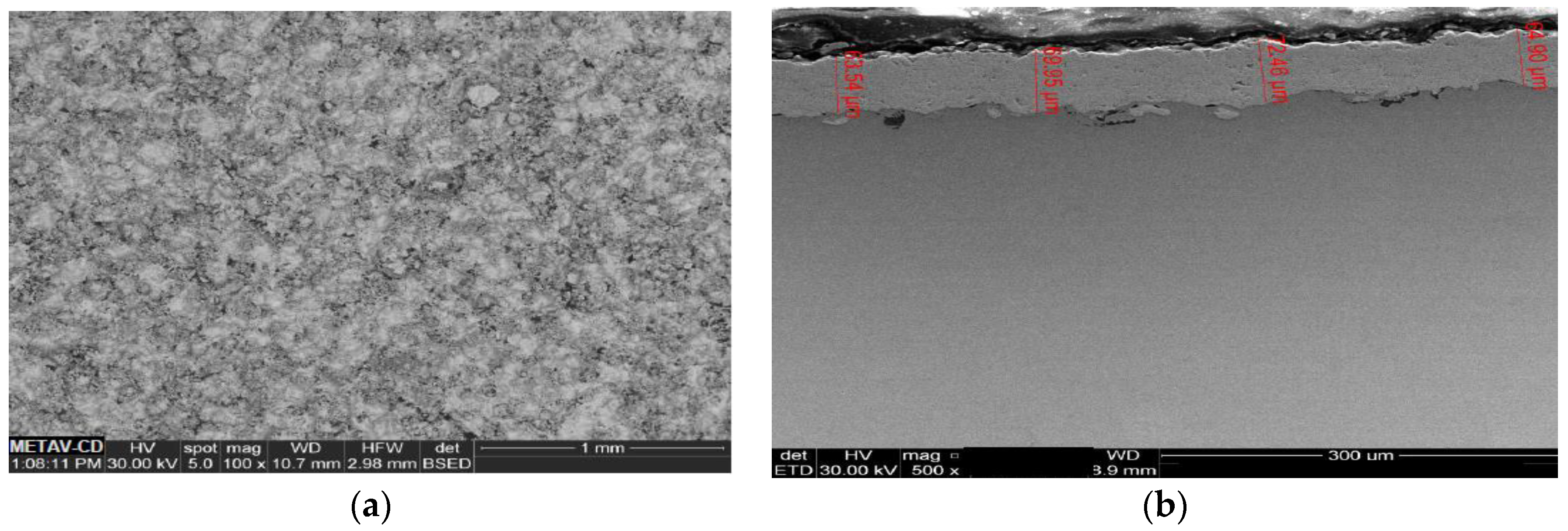
3.2. HVOF Coatings Characterization

The HVOF process, with high kinetic energy and low thermal energy comparative with the plasma ASP method, results in a positive effect on the coating characteristics and the technique is favorable for spray materials such as carbide coatings. When nickel is alloyed with chromium, this element oxidizes to Cr2O3 at rates which could make it suitable for use up to about 1200 °C [19]. In practice, the use is limited to temperatures below about 800 °C, and in this situation it’s recommended for uses in geothermal power plant components or for gases combustion systems [20]. HVOF coatings however produce very dense layers (Figure 9) with porosity under 0.5–1%. Formation of chromatic solute anions prevented sulphidation of the Ni20Cr10Al coated steel components, revealed that the coating exhibited good corrosion resistance and slurry wear. For typical ASP plasma coating deposition have approximately more one to two percent porosity. The addition of YO2 and NiCr to HVOF on sprayed fine Cr3C2 particles, improves the wetting and bond strength of the coatings to the substrate which decreases the tendency of brittle peeling during thermal deposition. These coating layers have higher hardness and improved elastic modulus with less cracks and pores.

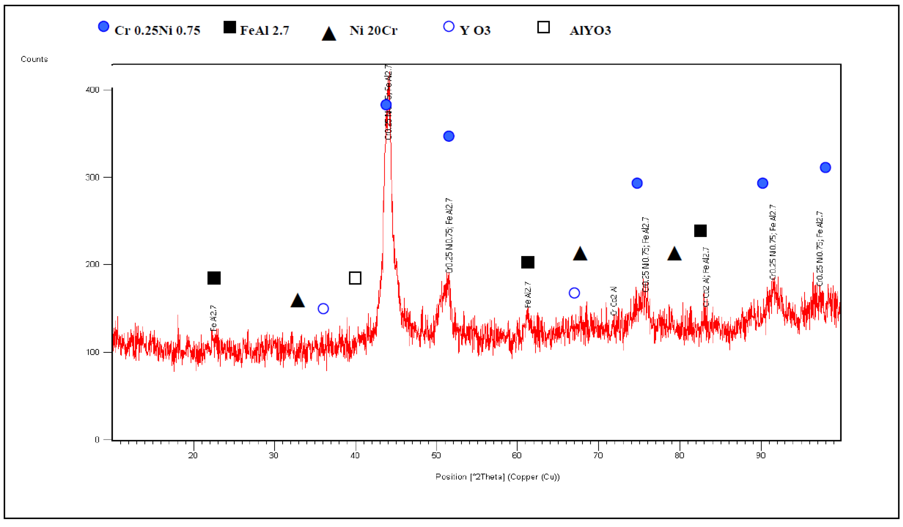
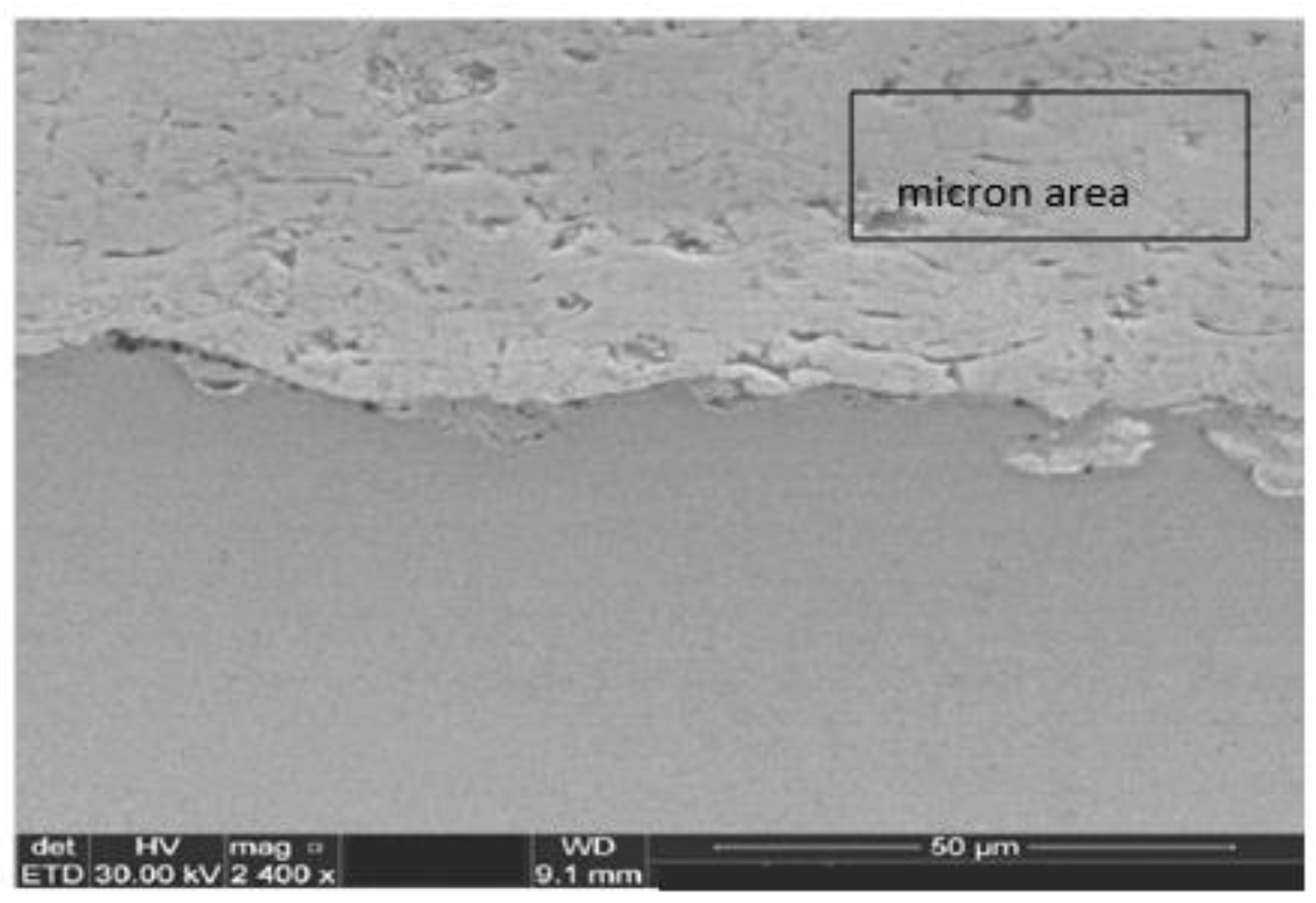
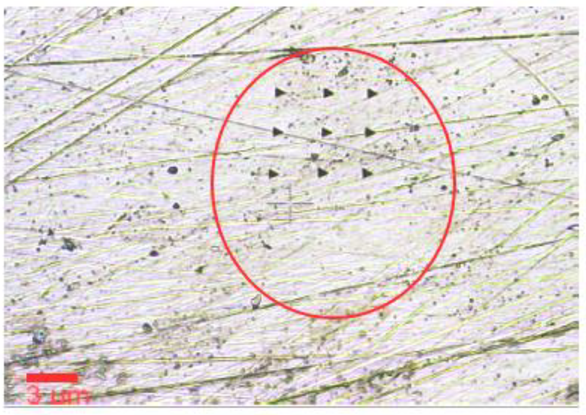
3.3. Microstructure and X-Diffraction

In this experiment the XRD analysis is a technique for the rapid determination of the samples homogeneity. It displays the spectrum of composition existing in a given inhomogeneous phases from the shape of diffraction peak broadened (Figure 10) by a range of lattice parameters in the phase. In the HVOF experimental deposition, the matrix has been built from (Ni,Cr)3Al, and Ni-Cr phases with small amounts of Al. The components Ni(Cr)–Y with different levels of Y were detected. Phase analysis by XRD method revealed that diffraction peaks correspond to Ni3Al and Ni phases. Additionally, Ni–Y compounds of NiY and Ni7Y type were confirmed as well. Probably, tertiary compounds from Ni–Y–Al system can exist as well.
The analysis by X-ray mappings for NiCrAlY-carbon steel coated indicate a scale consisting of a top layer containing oxides of nickel, chromium and aluminum. In the lower portion of the samples Ni-rich splats are encircled by oxides of aluminum. The element Cr is also seen forming stringers along the splat boundaries. Formations of spinel i.e., NiCr2O4 and Cr23C6, Cr7C3 phases have given their contribution to increase the oxidation resistance of coated carbon steel samples. The XRD pattern showed the brooded multiple diffraction peaks with low intensity, confirming the crystalline and fine size of the NiAl and the presence of Y2O3 components in the composites. The Y2O3 improves adherence and appalling resistance of oxide layer, and hence improves oxidation, sulfidation, and carburization resistance of surfaces composites. The major cubic Cr0.25Ni0.75 and orthorhombic FeAl2.7 phases and the minor Ni3Al phase were observed in the samples. The XRD pattern showed the brooded multiple diffraction peaks with low intensity, confirming the crystalline and fine size of the NiAl and Y2O3 components in the composites. The Y2O3 improves adherence and appalling resistance of oxide layer, and hence improves oxidation, sulfidation, and carburization resistance of surfaces composites. It is evident from the SEM micrographs of the coating deposition (Figure 11) that the Cr3C2-Ni20Cr powder gives a clear contrast between the carbide and NiCr matrix phases and the layer deposition shows shaped morphology. Figure 12 showing the Cr3C2-Ni20Cr HVOF coating. The detail illustrating the distribution of fine Ni20Cr carbides in the matrix.
The Cr3C2-NiCr coatings offer a greater corrosion and oxidation resistance. They also have a higher melting point, maintain high hardness, strength and wear resistance up to a maximum operating temperature of 900 °C. In addition to these features, the coefficient of thermal expansion of Cr3C2 (10.3 × 10⁻⁶ °C−1) is nearly similar to that of iron (11.4 × 10⁻⁶ °C−1) and nickel (12.8 × 10⁻⁶ °C−1); that constitute the base of the most high temperature alloys. The formation of phases like Cr2O3 and NiCr2O4 in the protective scale of the coatings was suggested to induce requisite resistance for geothermal carbon components steels.

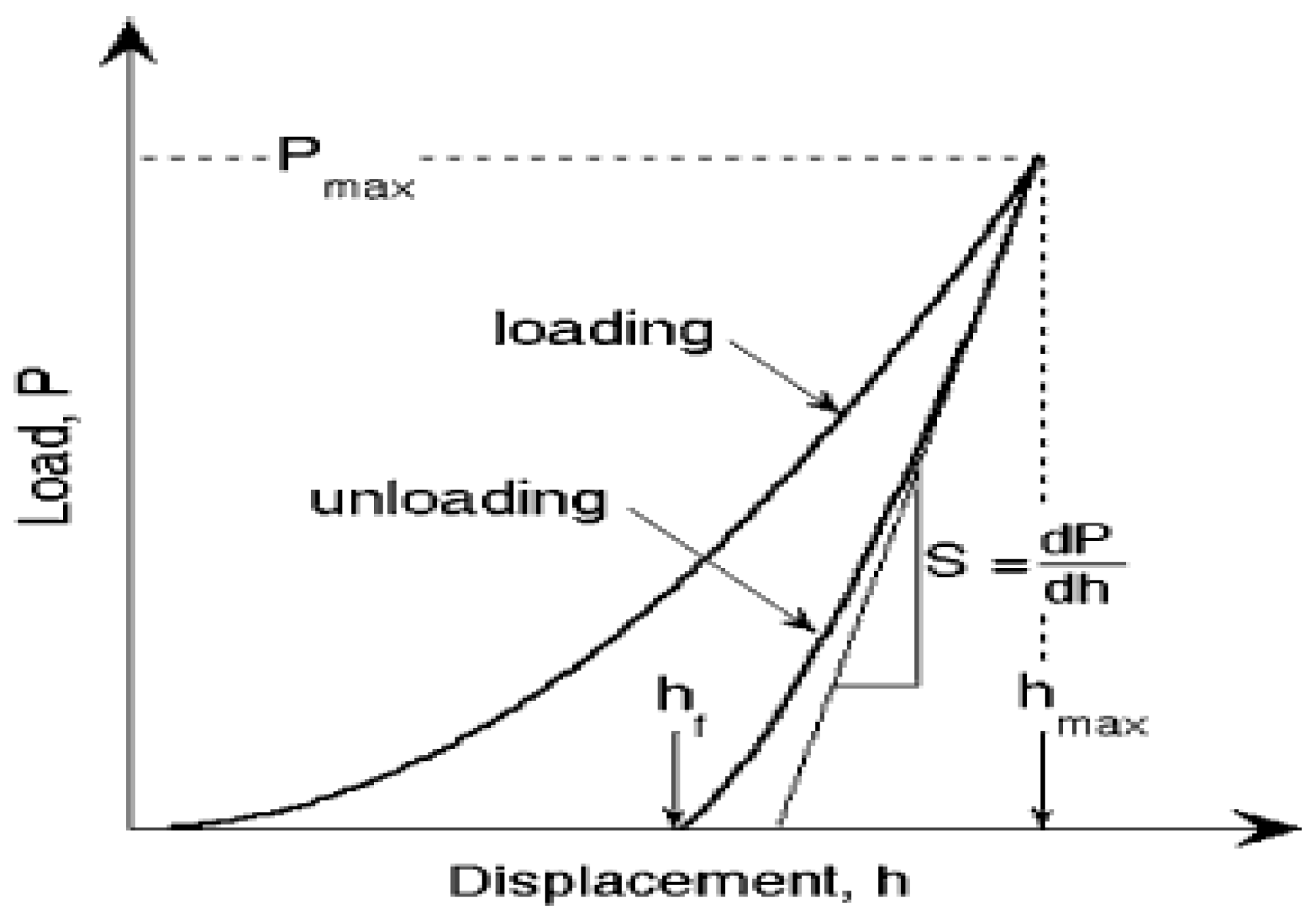
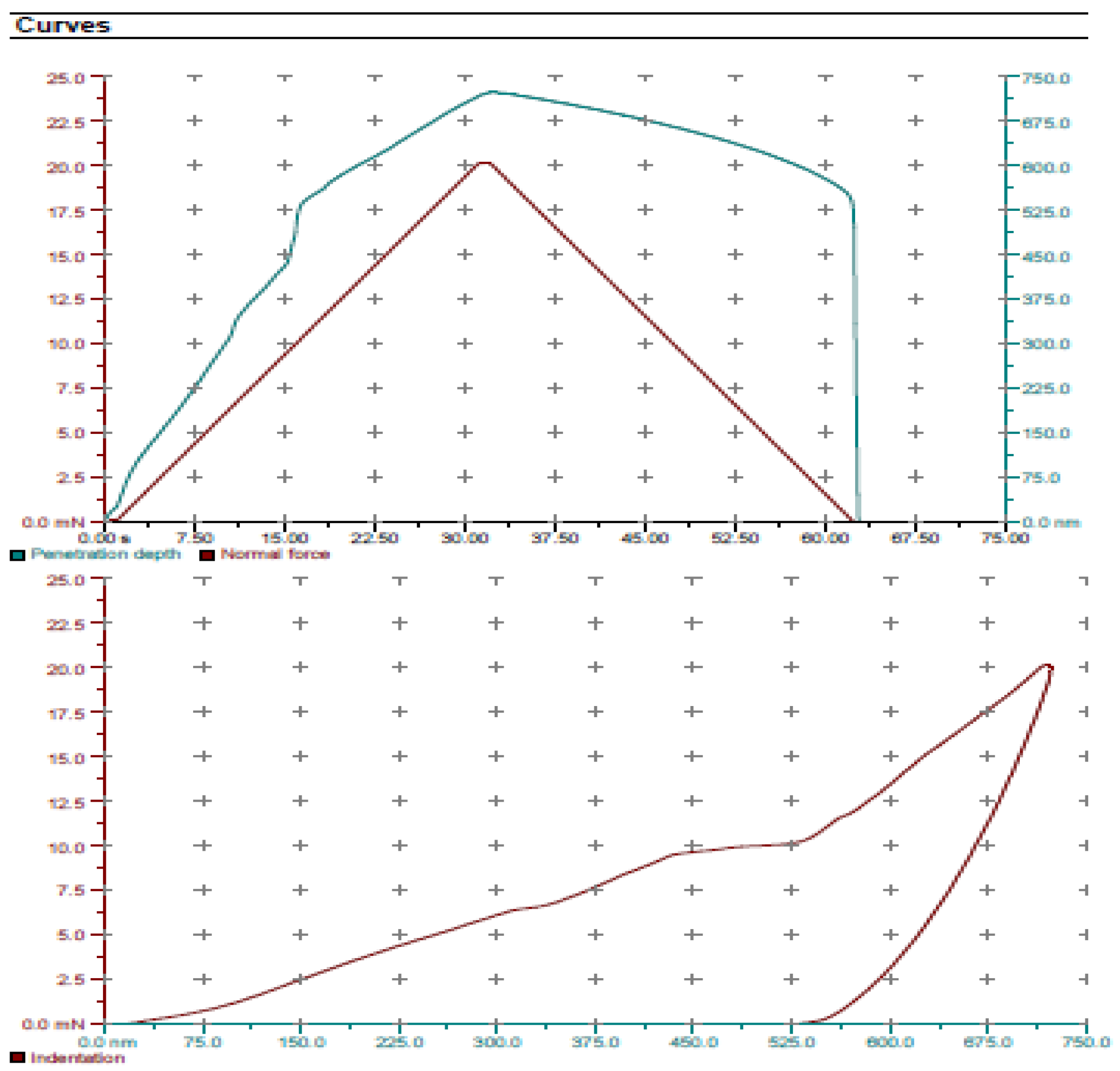
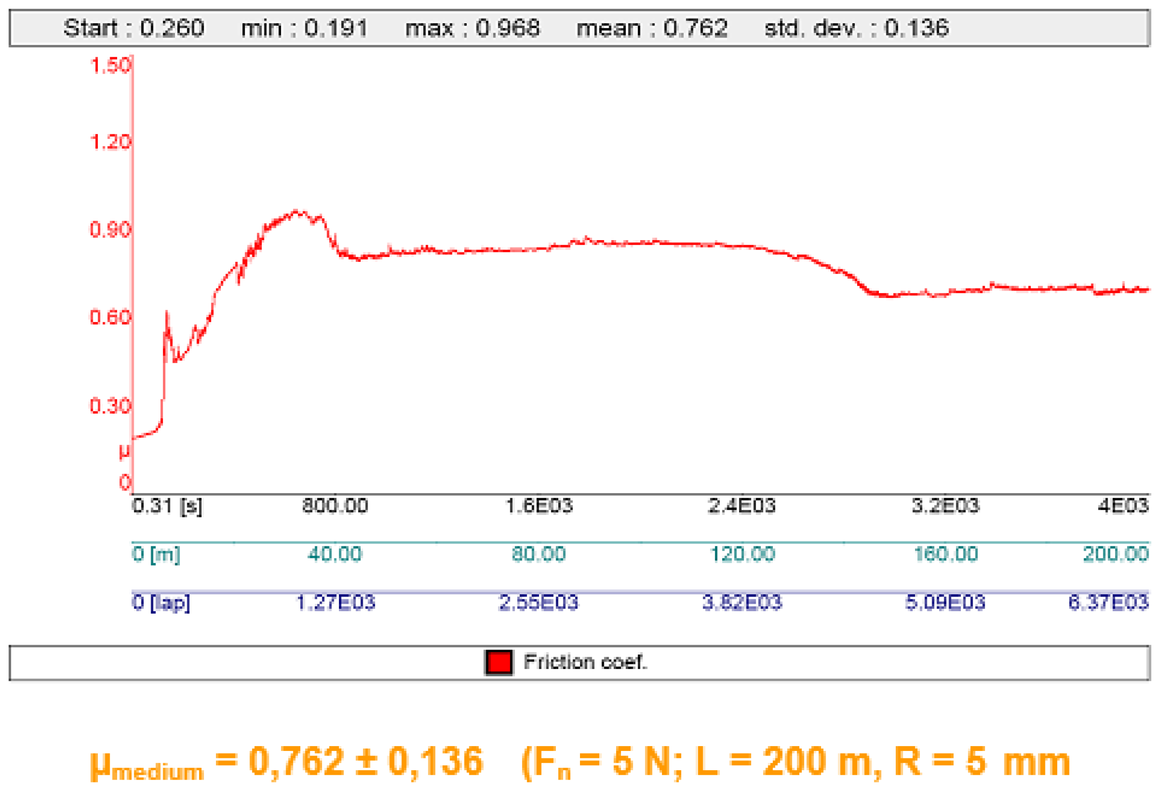
3.4. Mechanical Properties

A better understanding of the service behavior of such coatings is needed in order to determine metallurgical and mechanical interactions of these materials. The detailed evaluation of nano-mechanical properties in terms of hardness and Young’s modulus of composites HVOF coating have been evaluated by nano-indentation technique. The small indentation force (Figure 13) applied using the nano-indentation technique provides an ideal non-destructive mechanical testing solution to prevent damage to s coatings. The mechanical properties have been correlated with characteristics of the coating. Values of E are calculated from the load-displacement (Figure 14) data usually following the procedure proposed by Oliver and Pharr [21]. The pure elastic and elasto-plastic indentation curves were obtained by adjusting the indentation load magnitude (Figure 15). Tribological characterization by Pin on disc tests and determination of the friction coefficient and specific wear rate are presented in Figure 16.
The wear rate of coatings exhibited better tribological behaviors than the untreated steel. The characteristic plateau (Figure 16) corresponds to the quasi-constant wear rates. The characteristics were studied by nano-indentation test at ultra-low loads with a Berkovich indenter. The contact area function of the indenter was calibrated repeatedly under nano-scales and the indenter was estimated under different indentation depths reactively. Due to the heterogeneous and porous microstructure, the scatter of all collected experimental data was analyzed through the statistic method. In this context it is interesting to observe that the hardness exhibits an apparent reverse indentation size effect under very small depths. The Young’s modulus in boarded coating varies from 213 to 246 GPa due to the carburization effect. True hardness of layers increases from as-received 72.9 GPa to a top value 79.7 GPa. The boundary conditions of hardness measurement described should be considered to be a minimum requirement for elastic modulus measurements. Standard procedures are described in ASTM E 1876-99. A mechanical property mapping of composite coatings can play a key role in determining the mechanism and stages of the degradation layers of the coating process.

4. Conclusions

The XRD pattern showed the brooded multiple diffraction peaks with low intensity, confirming the crystalline and fine size of the NiAl and Y2O3 components in the composites. The Y2O3 improves adherence and appalling resistance of oxide layer, and hence improves oxidation, sulfidation, and carburization resistance of surfaces composites. The major cubic Cr0.25Ni 0.75 and orthorhombic FeAl2.7 phases were observed in the samples. Nano-test identation techniques revealed the 79.7GPa hardness measured on the coated surface sample of composite layers. The modulus and hardness of obtained composite depend on enhanced concentrations of particles near the surface and on the indentation depth. For small (1 μm) indentations, were obtained large increases in modulus (+40%) and hardness (+93%) to very high values to 1400 MPa. At no-larger indentation depth (700–800 nm, the modulus E and hardness of the quasi-homogeneous composites Ni20Cr10Al2Y were almost the same, and appropriate to mechanical properties of modulus of elasticity Ni20Cr. During wear test, the layer microstructure exhibited lower wear rate and the wear rate of coatings exhibited better tribological behaviors than the untreated steel.

Acknowledgments

The research leading to these results has received funding from EEA Research Program—GEOTUR 16SEE/2014 EEA and will be further continued by the contract No. LCE-GA-2018-764086, Geo-Coat, H2020.

References

  1. Cabral-Miramontes, J.A.; Gaona-Tiburcio, C.; Almeraya-Calderón, F.; Estupiñan-Lopez, F.H.; Pedraza-Basulto, G.K.; Poblano-Salas, C.A. Parameter Studies on High-Velocity Oxi-Fuel Spraying of CoNiCrAlY Coatings Used in the Aeronautical Industry. Int. J. Corros. 2014, 2014. [Google Scholar] [CrossRef]
  2. Souza, R.C.; Voorwald, H.J.; Cioffi, M. Fatigue strength of HVOF sprayed Cr3C2-25NiCr and WC-10Ni on AISI 4340 steel. Surf. Coat. Technol. 2008, 203, 191–198. [Google Scholar] [CrossRef]
  3. Masuku, Z.H.; Olubambi, P.A.; Potgieter, J.H.; Obadele, B.A. Tribological and Corrosion Behavior of HVOF-Sprayed WC-Co-Based Composite Coatings in Simulated Mine Water Environments. Tribol. Trans. 2015, 58, 337. [Google Scholar] [CrossRef]
  4. Matthews, S.; James, B.; Hyland, M. Erosion of oxide scales formed on Cr3C2-NiCr thermal spray coatings. Corros. Sci. 2008, 50, 3087–3094. [Google Scholar] [CrossRef]
  5. Chatha, S.; Sidhu, H.; Sidhu, B. Characterization and Corrosion-Erosion Behavior of Carbide based Thermal Spray Coatings. J. Miner. Mater. Charact. Eng. 2012, 11, 569. [Google Scholar]
  6. Wang, H.; Zuo, D.; Wang, M.; Sun, G.; Miao, H.; Sun, Y. High temperature frictional wear behaviors of nano-particle reinforced NiCoCrAlY cladded coatings. Trans. Nonferrous Met. Soc. China 2011, 21, 1322–1328. [Google Scholar] [CrossRef]
  7. Cao, Y.; Huang, C.; Liu, W.; Zhang, W.; Du, L. Effects of Boron Carbide Content on the Microstructure and Properties of Atmospheric Plasma-Sprayed NiCoCrAlY/Al2O3-B4C Composite Coatings. J. Therm. Spray Technol. 2014, 23, 716–724. [Google Scholar] [CrossRef]
  8. Shibata, M.; Kuroda, S.; Murakami, H.; Ode, M.; Watanabe, M.; Sakamoto, Y. Comparison of Microstructure and Oxidation Behavior of CoNiCrAlY Bond Coatings Prepared by Different Thermal Spray Processes. Mater. Trans. 2006, 47, 1638–1642. [Google Scholar] [CrossRef]
  9. Wang, B.-Q.; Verstak, A. Elevated temperature erosion of HVOF Cr3C2/TiC-NiCrMo cermet coating. Wear 1999, 233–235, 342–351. [Google Scholar] [CrossRef]
  10. Cunhaa, C.A.; Correaa, O.V.; Sayegb, I.J. High Temperature Erosion-oxidation Resistance of Thermally Sprayed Nanostructured Cr3C2-25(Ni-20Cr) Coatings. Mater. Res. 2017, 20, 994–1002. [Google Scholar] [CrossRef]
  11. He, J.; Ice, M.; Lavernia, E.J. Synthesis of nanostructured Cr3C2-25(Ni20Cr) coatings. Metall. Mater. Trans. A 2000, 31, 555–564. [Google Scholar] [CrossRef]
  12. Cunha, C.A.; Lima, N.B.; Martinelli, J.R.; Bressiani, A.H.; Padial, A.G. Microstructure and mechanical properties of thermal sprayed nanostructured Cr3C2-Ni20Cr coatings. Mater. Res. 2008, 11, 137–143. [Google Scholar] [CrossRef]
  13. SR EN ISO 3274:2001 Standard; Geometrical Product Specifications (GPS), Surface Texture: Profile Method. Nominal Characteristics of Contact (Stylus) Instruments. ISO: Geneva, Switzerland, 2017; Volume 4, pp. 2949–2962.
  14. SR EN ISO 4288:2002 Standard; Geometrical Product Specifications (GPS), Surface Texture: Profile Method. Rules and Procedures for the Assessment of Surface Texture. ISO: Geneva, Switzerland, 2002.
  15. DIN 50324; Tribology; Testing of Friction and Wear Model Test for Sliding Friction of Solids (Ball-on-Disc System). German Standard. 1992.
  16. ASTM G 133-95; Standard Test Method for Linear Reciprocating Ball-on-Flat Sliding Wear. ASTM International: West Conshohocken, PA, USA, 1995.
  17. Tao, K.; Zhou, X.; Cui, H.; Zhang, J. Microhardness variation in heat-treated conventional and nanostructured NiCrC coatings prepared by HVAF spraying. Surf. Coat. Technol. 2009, 203, 1406–1414. [Google Scholar] [CrossRef]
  18. Shukla, V.N.; Jayaganthan, R.; Tewari, V.K. Surface engineering analysis of HVOF sprayed Cr3C2-NiCr coating under high temperature oxidation. Int. J. Surf. Eng. Mater. Technol. 2014, 4, 44–49. [Google Scholar]
  19. Bolelli, G.; Berger, L.; Koivuluoto, H. Tribology of HVOF- and HVAF-sprayed WC-10Co4Cr hardmetal coatings: A comparative assessment. Surf. Coat. Technol. 2015, 265, 125–144. [Google Scholar] [CrossRef]
  20. Chatha, S.; Siduhu, H.S.; Siduhu, B.S. Characterization and Corrosion-Erosion Behaviors of Carbide based Thermal Spray Coatings. J. Mater. Charact. Eng. 2012, 11, 569. [Google Scholar]
  21. Oliver, C.; Pharr, G.M. An improved technique for determining hardness and elastic modulus using load and displacement sensing indentation experiments. J. Mater. Res. 1992, 7, 1564. [Google Scholar] [CrossRef]
Figure 1. HVOF process schematic representation.
Proceedings 02 01434 g001
Figure 2. The process of HVOF gun deposition of composite layers. The supersonic gas jet forms the stationary shock waves in the plasma jet.
Proceedings 02 01434 g002
Figure 3. Comparative flow rate determination for Ni based powders, under atmospheric condition.
Proceedings 02 01434 g003
Figure 4. SEM of gas atomized 20Cr10Al2Y complex powders.
Proceedings 02 01434 g004
Figure 5. SEM of the surface morphology revealing attached satellite particles adhered and the phenomenon of the coalesced particles.
Proceedings 02 01434 g005
Figure 6. SEM image of the surface morphology revealing the phenomenon of the primarily spheroids and highly coalesced.
Proceedings 02 01434 g006
Figure 7. EDS elemental Ni-Cr-Al mapping of powder particles.
Proceedings 02 01434 g007
Figure 8. EDS analysis results of the complex 20%Cr10%Al2%Y matrix-line scanning of the processed powder sample in SEM image.
Proceedings 02 01434 g008
Figure 9. SEM image of Ni20Cr10Al2Y coatings showing HVOF surface deposition (a), relatively uniform and dense structure in the section of the layer (b).
Proceedings 02 01434 g009
Figure 10. Indexing map of the X-ray diffraction pattern of textured matrix Ni20Cr10Al2Y. (2-Theta, deg).
Proceedings 02 01434 g010
Figure 11. The aspect of the Ni20Cr10Al2Y coating deposition.
Proceedings 02 01434 g011
Figure 12. The lamellae aspect of the coating is typical of structure produced on the matrix NiCrAlY by receive Cr3C2-Ni20Cr.
Proceedings 02 01434 g012
Figure 13. Optical imaging of the layer deposition and nano-identation Map in hardness determination of specimen.
Proceedings 02 01434 g013
Figure 14. Schematic illustration of indentation load-displacement data showing important measured parameters.
Proceedings 02 01434 g014
Figure 15. Quasi-uniform composite and dimensional nano-identation curves on coating (indentation depth in nm).
Proceedings 02 01434 g015
Figure 16. Values of the friction coefficient for the tribological samples test in air. (Vl = 5 cm/s, and WC ball of 6 mm diameter).
Proceedings 02 01434 g016
Table 1. Chemical composition of carbon steel substrates.
Elements
(wt %)
C
max
Mn
max
Si
max
P
max
S
max
N
max
Cu
max
Other
Composition0.200.20-0.0400.0400.0120.550.35
Table 2. Feature of the characteristics of experimental HVOF samples deposition.
GasVolumen Flow [SLPM] *Operating Pressure [MPa]
Oxygen250–3501.0
Propane40–800.05
Air450–6000.07
Powder feed35 g/min-
* SLPM = Standard Liters per Minute Gas consumption.
Table 3. Physical characteristics of the powder components.
Chemical Composition (wt%)Nominal Particle Size Distribution (μm)Apparent Density (g/cm3)Flow Rate (s/50 g)Manufacturing Method
Ni base
20%Cr; 10%Al; 2%Y
−53/+153.692.8Atomized particle
Publisher’s Note: MDPI stays neutral with regard to jurisdictional claims in published maps and institutional affiliations.

