Abstract
In this article, the performance of a radial flow turbine is determined in the framework of oscillating water column installations (OWC). The studied turbine redesigned and adapted from previous studies to this application, is analyzed in detail using CFD Fluent v16.2 and TurboGrid for mesh preprocessing. In particular, a 3D numerical model with high-quality hexahedral meshes (necessary to analyze the unsteady phenomena in the blade passages of the turbine) has been developed to obtain an enhanced prediction of the flow patterns. The results obtained through a full unsteady RANS resolution of the viscous and three-dimensional flow structures reveal the optimal performance of the radial turbine and confirm the expected improvements introduced during the redesign of the machine.
1. Introduction
Oscillating water column (OWC) wave energy converter is the primary conversion technique for converting wave energy to mechanical energy by the oscillating motion of the wave. Fluctuating bidirectional air flow generated by oscillating wave requires using a self-rectifying air turbine implying this advantage [1]. As shown in Figure 1 oscillating water column harness energy from the oscillation of the waves inside the hollow chamber which acts directly on the turbine [2].

Figure 1.
OWC schematic.
Radial turbine is a main type of bi-directional air turbines in which flow through rotor blades and the exit to the atmosphere though the OWC chamber is radially configured as it can be observed in McCormick et al. [3] investigated experimentally the performance of the radial turbine in a single-stage setting containing one row of rotor blades and two rows of stator blades comparing between the radial and the axial turbines and it was found higher runaway speed in the radial setting with a value of 25%. Setoguchi et al. [4] conducted an experimental parametric study for the radial turbine varying the inner and outer guide vane angles recommending a 25° orientation for the vanes. Further studies were proposed by Takao et al. (2005) [5] investigating the effect of using pitch-controlled guide vanes and found an increase by 15% compared to fixed guide vanes.
Various numerical studies performed on radial turbine by B. Pereiras et al. [6] modeled a new radial impulse turbine geometry after validating it with previous experimental work [4]. B. pererias [7] went further in studying the Tip clearance phenomena on the performance of the radial turbine leading to introducing a new geometry for the radial impulse turbine [8] increasing the efficiency by 5% compared to [4].
This paper presents the performance calculations for the radial turbine implemented in OWC using a new meshing technique provided by Turbogrid for all blades in Ansys 16.2 package. The main goal of the present study is to numerically investigate the flow and obtain the performance curve of a radial turbine used in a OWC installation. A change in the angle of the Inlet Guide Vanes (IGV) and Outlet Guide Vanes (OGV) has been introduced in order to find an optimized geometry, following a similar idea as [4,8].
2. Numerical Model
To be able to build a proper numerical model for the turbine geometry and correctly solve the flow variables, Ansys V16.2 has been used. The model was built with one row for the IGV, a rotor row and one OGV row. This last OGV stands as an elbow, as can be observed in Figure 2.
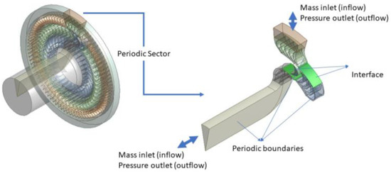
Figure 2.
Numerical model domain and boundary conditions.
Simulation was conducted using FLUENT V16.2 using the finite volume method and sliding mesh technique for the moving parts of the turbine. The speed of the rotor was constant at 234 rpm. Hexaedrical grid consisting of 1 million cells is implemented for simulation, see Figure 3 for a general view.
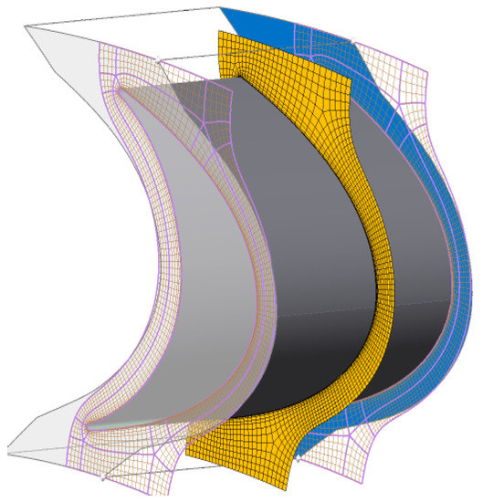
Figure 3.
Blade mesh.
Details of turbine geometry in Figure 4 could be found in Ref. [8]. Using a validated model Ref. [8], the setting angle for IGV and OGV was changed to 25°. Additional geometrical arrangements are shown in Table 1.
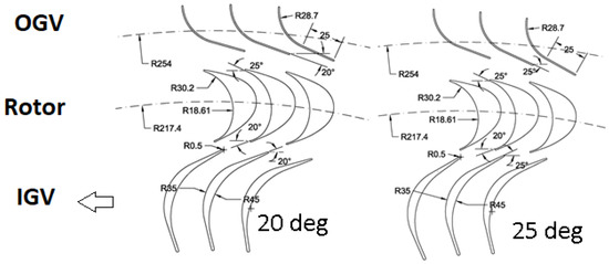
Figure 4.
M16 Geometry 20°/25°.

Table 1.
geometrical characteristics.
Periodic boundary conditions were used to simulate an even part of the turbine as shown in Figure 2 to reduce computational time and to improve numerical accuracy dividing the turbine into 17 equal parts. Realizable K-e turbulence model was used was non-equilibrium wall functions for the incompressible flow model. Highest order MUSCL scheme coordinated in the discretization, simple algorithm has been used in pressure-velocity coupling. Flow characteristics was evaluated by solving equation in 3D turbine geometry.
3. Performance Analysis
3.1. Turbine Characteristics
Steady flow conditions were used in conducting the turbine performance analysis expressed in terms of the torque coefficient CT, input coefficient CA and efficiency η and flow coefficient φ.
3.2. Numerical Model Validation
The model was validated using experimental data from the bibliography. See details in Pereiras et al. Ref. [8].
3.3. Performance Analysis for 25° Setting Angle
Results were conducted after changing the setting angle for the IGV and the OGV of the turbine Figure 4. On the other hand, Figure 5 analyzes the turbine performance in 3 means first the CT and it has been found increase in the rotor torque as a result of changing the angle of IGV guiding more flow towards the rotor blades in the inflow process despite no change was noticed in the outflow process assuring that the orientation of the OGV don’t affect the rotor torque. Same phenomena could be found the input coefficient for the turbine showing increase only in the inflow process not the outflow. The efficiency curve concludes what had been notified in the CT and the CA showing an obvious increase in the efficiency during the inflow but same during the outflow.
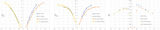
Figure 5.
Performance criteria for M16 geometry with 25° setting angle.
4. Conclusions
In this article, it has been developed a numerical model using TurboGrid which is a very powerful tool for generating meshes special for blades and vanes. This model improved by changing the setting angles of the guide vanes resulting in increase in the turbine efficiency.it has been noticeable increase in the turbine efficiency at 0.75 flow coefficient as a result of increasing torque coefficient and input coefficient accordingly with the flow coefficient. The increase in the efficiency prove that the guide vanes is the main source of energy loss specially the IGV as the loss is accompanied with the spline of the vane.
References
- Heath, T.V. A review of oscillating water columns. Phil. Trans. R. Soc. A 2012, 370, 235–245. [Google Scholar] [CrossRef] [PubMed]
- Evans, D.V. The oscillating water column wave-energy device. IMA J. Appl. Math. 1978, 22, 423–433. [Google Scholar] [CrossRef]
- McCormick, M.E.; Rehak, J.G.; Williams, B.D. An experimental study of a bidirectional radial turbine for pneumatic wave energy conversion. In Proceedings of the OCEANS’92, Mastering the Oceans Through Technology, Newport, RI, USA, 26–29 October 1992; Volume 2, pp. 866–870. [Google Scholar]
- Setoguchi, T.; Santhakumar, S.; Takao, M.; Kim, T.H.; Kaneko, K. A performance study of a radial turbine for wave energy conversion. Proc. Inst. Mech. Eng. Part A J. Power Energy 2002, 216, 15–22. [Google Scholar] [CrossRef]
- Takao, M.; Fujioka, Y.; Homma, H.; Kim, T.W.; Setoguchi, T. Experimental study of a radial turbine using pitch-controlled guide vanes for wave power conversion. Int. J. Rotat. Mach. 2006, 2006, 17379. [Google Scholar] [CrossRef]
- Pereiras, B.; Castro, F.; El Marjani, A.; Rodríguez, M.A. Radial Impulse Turbine for Wave Energy Conversion: A New Geometry. In Proceedings of the ASME 2008 27th International Conference on Offshore Mechanics and Arctic Engineering, Estoril, Portugal, 15–20 June 2008; pp. 841–850. [Google Scholar]
- Pereiras, B.; Castro, F.; el Marjani, A.; Rodríguez, M.A. Tip clearance effect on the flow pattern of a radial impulse turbine for wave energy conversion. J. Turbomach. 2011, 133, 041019. [Google Scholar] [CrossRef]
- Pereiras, B.; Castro, F.; El Marjani, A.; Rodríguez, M.A. An improved radial impulse turbine for OWC. Renew. Energy 2011, 36, 1477–1484. [Google Scholar] [CrossRef]
Publisher’s Note: MDPI stays neutral with regard to jurisdictional claims in published maps and institutional affiliations. |
© 2018 by the authors. Licensee MDPI, Basel, Switzerland. This article is an open access article distributed under the terms and conditions of the Creative Commons Attribution (CC BY) license (https://creativecommons.org/licenses/by/4.0/).