1. Introduction
The misalignment is the most common latent anomaly in a rotating system after imbalance. Several factors can cause this failure and lead to other future operating anomalies such as: strong imbalances, material wear, bearing failures, bearing supports, lubrication failures, etc. The cyclic charges can produce microscopic surface discontinuities, that act as tension concentrated, and therefore, as nucleation sites of cracks [
1,
2].
The horizontal shaft turbines have a model similar to the
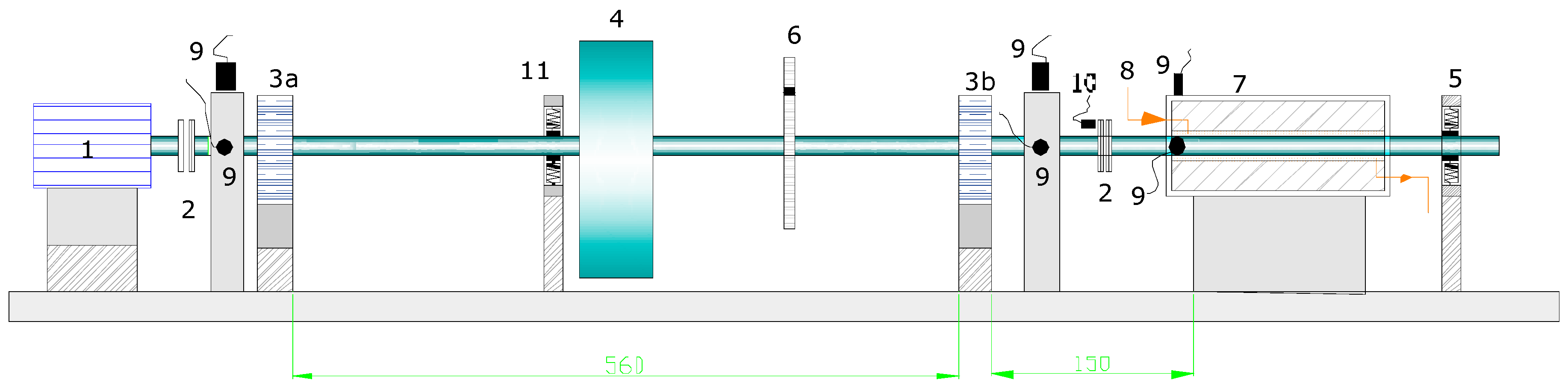
Figure 1, where a transmission shaft receives the thrust of the rotor at low rpm (30 rpm), and then a gear multiplier 1/50 raises this speed and is coupled to the electric generator, at 1500 rpm.
In the first shaft of transmission of the rotor, that is the longest, two induction transducers must be installed located at 90° in the vertical and horizontal plane (marks 1 and 2 in
Figure 1) and another in the middle of this shaft to identify modal analysis (mark 3 in
Figure 1). The transducers 1 and 2 will serve to analyse the differences of the response to vibration in both planes and for the configuration of the orbit that describes the centre of the shaft.
The process is carried out in differentiated steps: The test is started with a crack located at a distance of 12 mm from the bearing 3b (
Figure 2), with a “v” shape, a depth of 10% on a steel shaft of diameter 9.5 mm, a disc/rotor of mass 0.47 kg and a length between bearings of 560 mm. Subsequently, a radial load is introduced which will be increased in progressive values to simulate the load that the misalignment would produce, and thus the propagation of the crack will be observed.
2. Materials and Methods
The dynamic system of rotation that is analysed, corresponding to a Tidal Turbine, can be assimilated to the possible failures in a rotor of tests, for the best simulation of the real models of Tidal Turbines that are experienced.
The dimensions of rotor are 165 × 340 × 789 mm, shaft diameter of 9.5 mm and maximum speed of 10,000 rpm. It also has a coupling device to the shaft, that constitute a mechanical seal or bearing in a pressurized fluid environment contained in a transparent polycarbonate shell, and its accessories: two induction transducers and another phase reference, plus a load spring frame to simulate shaft eccentricities.
The model of rotor tested is indicated in the
Figure 2 that is similar to the model of the horizontal shaft turbine of the
Figure 1, where: 1. 75 W cc drive motor, 2. flexible coupling, 3. antifriction/bronze bearings, 4. 1.63 kg disc-rotor, 5. shaft centring support with four springs, 6. aluminium disc for controlled imbalances, 7. mechanical seal of 50 mm in length with radial clearance of 220 μm and a circuit pressure of 10,342 Pa, 8. pressurized oil circuit in the gap of the seal, 9. horizontal and vertical induction transducers and phase reference transducer, 10. induction transducers for axial vibration, 11. radial load application spring.
The model tested responds to the “Jeffcott rotor” type, with a single disc/mass, supported by two elastic bearings. In this model, it is assumed that it has the same stiffness in the “
x” and “
y” axes:
k =
kx =
ky; being the mathematical model of the movement [
3]:
where:
m = mass of the rotor,
h = eccentricity of the mass,
g = acceleration of gravity,
d = shaft damping coefficient,
ξ and
η are the rotary axes,
kη and
kξ = shaft stiffness in the directions of the crack and perpendicular to it, respectively,
kξη and
kηξ are the coupling stiffness between both shafts,
ω the speed of rotation, and
δ the angle between the centre of gravity and the geometric centre.
The characteristics of this test rotor, before originating the crack in the shaft, that were calculated as indicated [
4], are: Natural rotor frequency, without crack, 2535 rpm (265.47 rad/s); Modal stiffness coefficient, K = 4.65 × 10
3 KN/m.
3. Results
The process is carried out in differentiated steps:
1. The test is started with a crack located at a distance of 12 mm from the bearing 3b with a “v” shape (Figure 2), a depth of 10% of the diameter on a steel shaft of diameter 9.5 mm, a disc/rotor of mass 0.47 kg and a length of shaft between bearings of 550 mm, but without added radial load, in order to obtain in principle the following parameters: Natural frequency = 258 rad/s = 2463.71 rpm.; Modal stiffness coefficient K = 3.65 × 10³ KN/m.
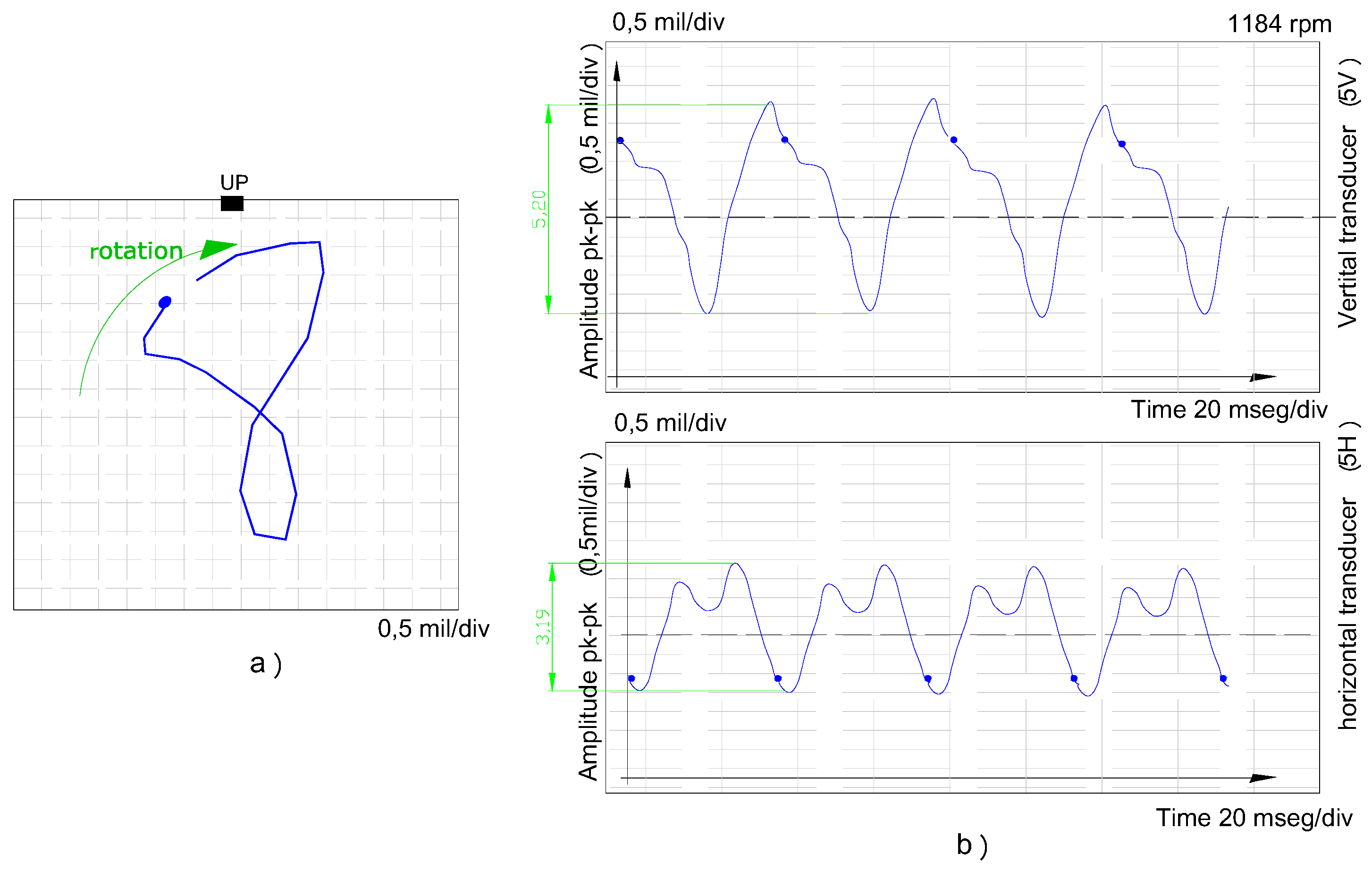
2. Then, by applying the spring (numbered 11 in Figure 2) a radial load is induced in the vertical plane of 81 N, and the test is carried out holding this load for a time of 16 h. The response of Figure 3 is obtained, in which the internal loop in the orbit in the form of “eight” can already be observed (graphic a) of Figure 3), which is identified with the appearance of the 2X response as a consequence of the radial load, as well as an asymmetry in the signal of both transducers .
At the end of the period of time analysed, the propagation of the crack is already significant and the answer obeys to
Figure 3, in which this asymmetry is reached: 5,20 mils and 3,19 mils in the vertical and horizontal transducers, after 16 h (graphic b) of
Figure 3).
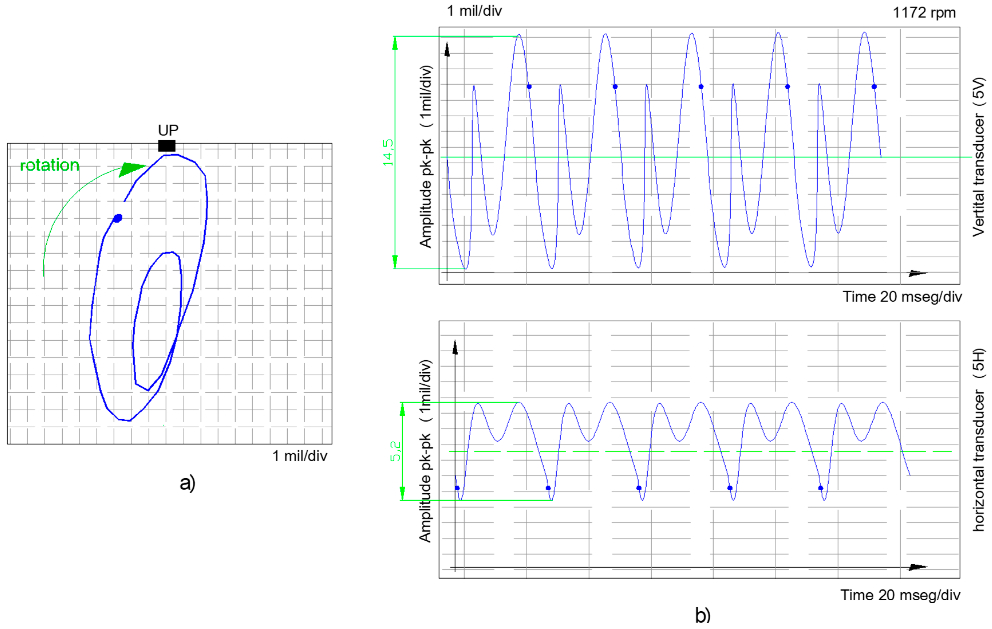
3. Afterwards, the test of the propagation of the crack is retaken by applying the radial load made with the spring module. The next load that is applied increases to a value of 118 N, which is maintained for a period of 12 h. The orbit shapes and the signals of the transducers installed at 90° are shown in Figure 4, where a large asymmetry is already noticed between the vertical plane that corresponds to the radial load introduced and the other horizontal plane.
A clear propagation of the crack [
5] is deduced in
Figure 4, the amplitude increases up to 14.5 mils in the 5 V transducer, identified on the axis containing the crack, while in the perpendicular direction, transducer 5 H, the amplitude does not show that increase, only reaches 5.2 mils.
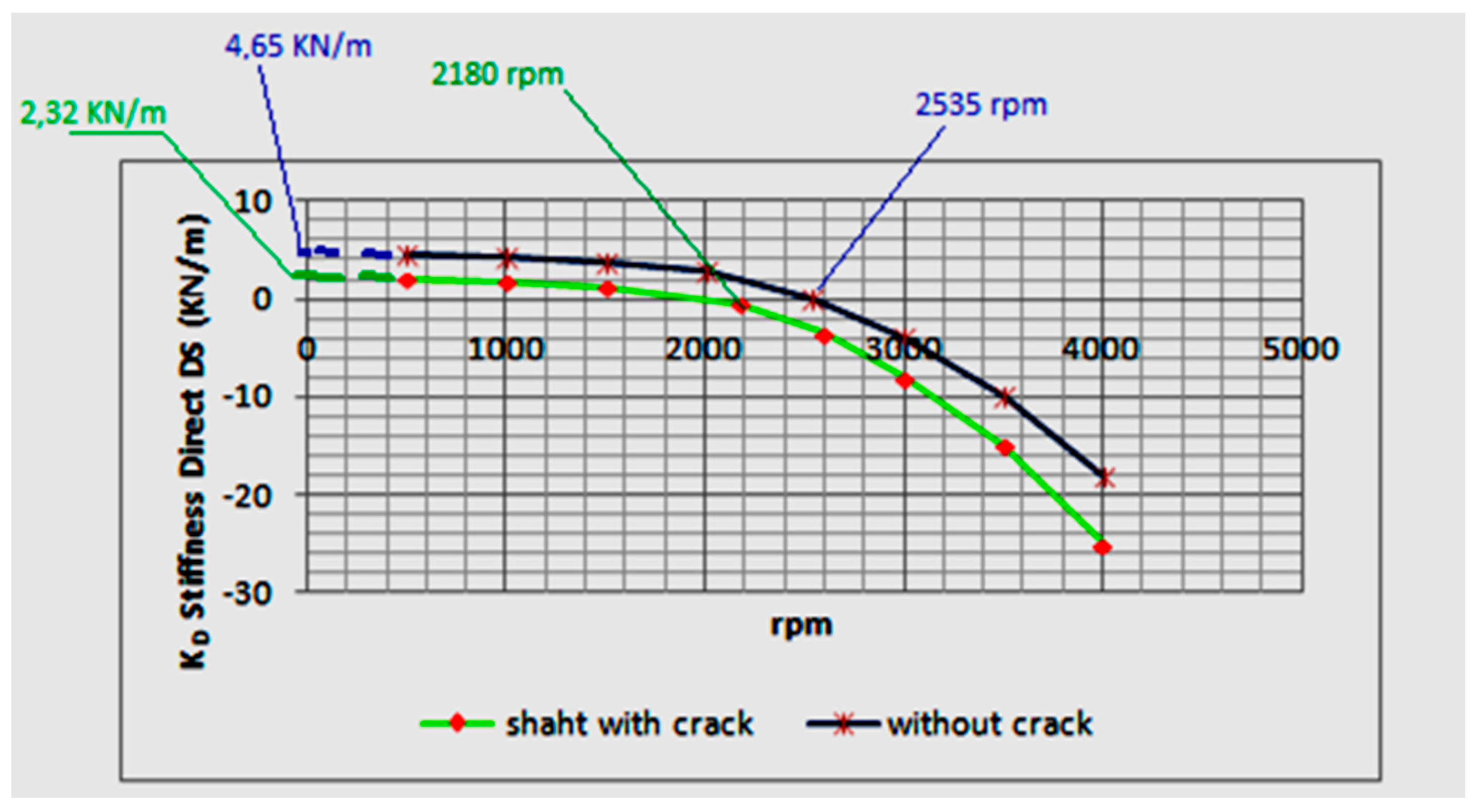
4. Another important characteristic of the crack is the reduction of the stiffness of the shaft and, consequently, of the resonance frequency [6].
Different tests, with the same determined weight of imbalance 0.1 g < 90° and a radial position of 70 mm at different speeds of rotation, give rise to the responses of
Figure 5: a parabola for the component of the real dynamic stiffness Z
D = K − MΩ
2. In this figure it is observed how this K
D component, which is determined by extending the parabola to the ordinate axis (Ω = 0 rpm), is 2,32 × 10
3 N/m with the propagation of the crack, thus decreasing with respect to the value of that rotor without crack of 4,65 × 10
3 N/m. Likewise, the first natural frequency of resonance decreases, of 2535 rpm (without crack) at 2180 rpm, in this case, facts that are clearly identified with the crack made and grown by the radial load [
7].
