Extended Abstract

Power Flow Management in a Wind Generation System Using a Dual Feed Induction Generator †

by
Pedro Hernández Tenorio
1,
Jaime José Rodríguez Rivas
1,
Oscar Carranza Castillo
1,2,*,
Rubén Ortega González
1,2 and
José Victoriano Chávez Aguilar
1
1
Instituto Politécnico Nacional, Escuela Superior de Ingeniería Mecánica y Eléctrica, Ciudad de Mexico 07738, Mexico
2
Instituto Politécnico Nacional, Escuela Superior de Computo, Ciudad de Mexico 07320, Mexico
*
Author to whom correspondence should be addressed.
Presented at Environment, Green Technology and Engineering International Conference (EGTEIC 2018), Caceres, Spain, 18–20 June 2018.
Proceedings 2018, 2(20), 1269; https://doi.org/10.3390/proceedings2201269
Published: 22 October 2018

Abstract

:
The management of the power flow of a wind generation system is presented. This system is made up of a doubly fed induction generator and a Back to Back converter. The analysis focuses on the grid-side converter. The control loops of the current to the grid and the voltage of the DC-Link are designed based on proportional-integral controllers. These controls allow to manage the active and relative power that is injected into the grid. The Converter is simulated in Simulink of Matlab, where its operation as a rectifier and inverter is validated. This is able to be done due to the vector control technique used in the control structure of the wind generation system, in addition an adequate power exchange is obtained between the generator and the grid.

1. Introduction

Photovoltaic energy, as well as, wind energy has been placed as alternative energy sources to conventional ones, since they do not produce greenhouse gases, apart from being from renewable sources, such as sun energy and wind energy [1]. For this work a Wind Generation Systems (WGS) based on a generator of the Double Fed Induction Generator (DFIG) type is considered as shown in Figure 1. In this generation topology, there is a variable speed wind turbine, which is connected to a DFIG through a gearbox, the winding of the stator of the DFIG is connected to a winding of a three-phase transformer, while the winding of the rotor, is connected to an Electronic Power Converter (EPC), better known as Back-to-Back Converter (BBC).
The BBC is made up of two three-phase converters, which are joined by a DC_Link, where the Generator Side Converter is connected to the rotor winding, providing the voltage of the DC_Link, while the Grid Side Converter (GSC) is powered by the voltage on the DC_Link. Therefore, both converters have the ability to work as a rectifier or as an inverter, depending on the direction of the power flow. The BBC guarantees the generation of power at nominal frequency of the grid and nominal voltage of the grid, regardless of the speed at which the rotor rotates [2]. This work focuses on the control of the Grid Side Converter, analyzing its two modes of operation: as a DC voltage supply source (rectifier mode), where the power flows from the grid to the BBC, and in the operating mode as an inverter, where the power flow goes from the BBC to the grid. To carry out the control of the GSC, the Vector Control is used and the voltage and current controllers are designed, in charge of controlling the voltage on the DC_Link and controlling the active and reactive power generated. The converter is validated by simulation.

2. Grid Side Converter

First, it is necessary to model the grid in a Synchronous Reference Framework (SRF), to subsequently apply the Vector Control, so it is required to transform the coordinates of a Three Phase Stationary Frame (Xabc) to a SRF (Xdq), using the Clarke and Park transformations, respectively. In Figure 2, the electrical diagram of the three-phase grid and the GSC is shown. The converter is modeled with bidirectional switches, where the ideal switch is usually created by IGBT (Insulated Gate Bipolar Transistor) with a diode in antiparallel. To carry out the connection of the GSC with the grid, an L filter is used, where the resistance of the inductor is included.
The three-phase system abc in the Synchronous Reference Frame (MRS) with components dq is composed of a real part and an imaginary part [3], as shown in (1):
V d f = R f i d + L f d ( i d ) d t ω s i n c L f i q + V d   and V q f = R f i q + L f d ( i q ) d t + ω s i n c L f i d + V q
In (1), there is a coupling due to iq in Vdf and id in Vqf, applying the vector control, it is possible to obtain the decoupling of said currents. To make this possible, the axis d of the synchronous frame is aligned with the spatial vector of the grid voltage V d q [2].
V d = | V d q |     and       V q = 0
Due to 2, (1) is modified:
V d f = R f i d + L f d ( i d ) d t       and   V q f = R f i q + L f d ( i q ) d t    
From (3), the current controllers required to control the GSC current are obtained, because the two functions are identical, the design for one controller is applied and applied to the other.

3. Current Controller Design

Applying the Laplace transform to (3), the transfer function of the GSC current controller is obtained, for both axes d and q:
I d ( s ) V d ( s ) = 1 s L f + R f = I q ( s ) V q ( s )
The open-loop transfer function ( G l a _   i ) and the closed loop transfer ( G l c _   i ) function are:
G l a _   i ( s ) = ( k p i + k i i s ) ( 1 s L f + R f )   and   G l c _   i ( s ) = ( G l a _   i 1 + G l a _   i )    
The values of R f = 0.5585 Ω and L f = 9.0897 mH are known. For the current controller, a crossover frequency ω c _ i = 300 Hz and an MF = 60° is proposed [4]. With the data that is calculated k p i = 14.5589 and k i i = 17,060.0.

4. Voltage Controller Design

The DC_Link is in constant exchange of energy; its main purpose is to maintain the established voltage in its terminals. To ensure that a power supply will provide a regulated output voltage, established by a setpoint or reference signal, a closed loop must be present. The transfer function of the DC_Link voltage regulator is obtained:
v ^ C D ( s ) i ^ d ( s ) | v ^ d = i ^ g = 0 = V d s C V C D + I g = V d s C V C D I g  
For the design of the voltage controller, the open-loop transfer function of the DC_Link ( G l a _   C D ), consider all the elements that are in your direct path:
G l a _   C D ( s ) = ( k p C D + k i C D s ) ( G l a _   i 1 + G l a _   i ) ( V d s C V C D I g )
Therefore, a bandwidth is proposed for the voltage loop, 10 times less than the bandwidth of the current controller. So, the crossover frequency is ωc_CD = 30 Hz and an MF of 60˚ is established. It is known that VLL = 220 V, VCD = 360 V, C = 2200 μF. The values of the gains of the tension controller are obtained: k p C D = −0.5804 and k i C D = −61.8415. When a controller contains integrating elements, when performing the integration process on the error signal, a very high value can be obtained, which causes the integrator to saturate, this is known as “windup” or saturation effect [5]. For this work an antiwind-up technique is applied through a conditional integration, this technique consists in disabling the integrating part until an established condition is fulfilled.

5. Results

The simulation results that were made in this work are presented. The load of the DC_Link capacitor, with the anti-windup and Delay function, is shown in Figure 3. In a first stage, only proportional control is applied, due to this an error is obtained between the voltages of VCD of the converter and the voltage VCD* reference, which is marked between two arrows. When disabling the antiwind-up condition, in time 0.24 s, the proportional-integral control is applied, causing the error between both voltages to be practically zero.
Figure 4 shows the active and reactive power generated by the converter, where the active power generated in this mode of operation is minimal and close to zero (P = 0 W), since the output of the voltage controller is zero when the complete control (PI) is applied, while the reactive power generated has a value Q = −1100 VARs.
Figure 5 shows that the active power generated by the converter is P = 1100 W, while the reactive power has a value close to zero (Q = 0 VARs), this is because the reference in the q axis is zero. Figure 6, it is observed that in the time 0.02 s, the converter begins to generate currents, where the currents are in phase with the voltages of the grid.

6. Conclusions

The management of the power flow in the wind generation system is carried out in a stable manner. This is because the current and voltage control loops are designed properly. The results were adequate in the two modes of operation of the grid-side converter, that is inverter mode and rectifier mode. With the technique of vector control, a correct decoupling of currents from the converter is achieved, which allows total control over the active and reactive power that is exchanged between the wind generation system and the grid.

References

  1. Hamdan, M.O.; Hejase, H.A.; Noura, H.M.; Fardoun, A.A. ICREGA’14-Renewable Energy: Generation and Aplications; Springer: Cham, Switzerland, 2014. [Google Scholar]
  2. Abad, G.; López, J.; Rodríguez, M.A.; Marroyo, L.; Iwanski, G. Doubly Fed Induction Machine, Modeling and Control for Wind Energy Generation; Wiley: Hoboken, NJ, USA, 2011. [Google Scholar]
  3. Bose, B. Modern Power Electronics and AC Drivers; Prentice Hall: Upper Saddle River, NJ, USA, 2002. [Google Scholar]
  4. Garcerá, G.; Figueres, E.; Abellán, A. Conversores conmutados: Circuitos de Potencia y Control; Servicio de Publicaciones: Valencia, Spain, 1998. [Google Scholar]
  5. Seok, J.K.; Kim, K.T.; Lee, C.D. Automatic Mode Switching of P/PI Speed Control for Industry Servo Drives Using Online Spectrum Analysis of Torque Command. Industrial Electronics. IEEE Trans. 2007, 54, 2642–2647. [Google Scholar]
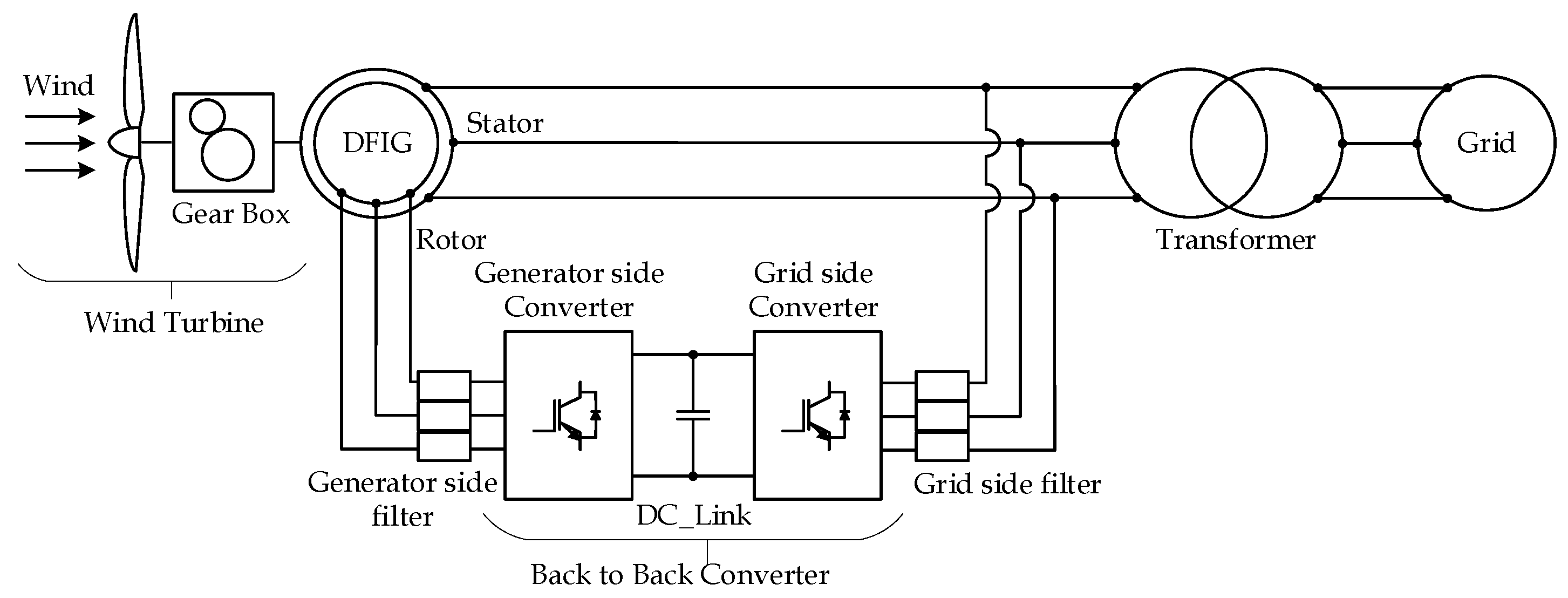
Figure 1. Wind Generation System with a Double Fed Induction Generator.
Proceedings 02 01269 g001
Figure 2. Electrical diagram of the three-phase grid and converter on the side of the grid.
Proceedings 02 01269 g002
Figure 3. Load of the DC_Link.
Proceedings 02 01269 g003
Figure 4. Reactive power generated.
Proceedings 02 01269 g004
Figure 5. Active power generated.
Proceedings 02 01269 g005
Figure 6. Converter currents and grid voltages.
Proceedings 02 01269 g006
Publisher’s Note: MDPI stays neutral with regard to jurisdictional claims in published maps and institutional affiliations.