1. Introduction
In the past, a lot of work has been carried out in the field of piezoelectric energy harvesters. From literature, three categories of piezoelectric energy harvesters can be identified namely, thin film/bulk piezoelectric energy harvesters [
1], piezoelectric nanowire energy harvesters [
2], and piezoelectric nanofiber energy harvesters [
3]. Piezoelectric polymer-based energy harvesters are particularly attractive because of their lightweight, low cost, and mechanical flexibility. Of all the piezoelectric polymers, polyvinylidene fluoride (PVDF) and its copolymers are most widely used.
This work presents the optimization of electrospinning parameters for electrospun PVDF nanofibers fabricated by the far field electrospinning (FFES) process. The electrospun nanofiber webs are characterized by means of scanning electron microscopy and Fourier transform Infrared (FTIR) spectroscopy to study their piezoelectric properties and morphologies. Finally, a nanofiber web fabricated with the optimized electrospinning parameters is subjected to a series of tapping tests for demonstrating their suitability for sensing and energy harvesting applications.
2. Experimental
For electrospinning experiments, PVDF powder (MW 534,000) (1.5 g), is mixed with dimethylformamide (DMF) (3 mL), and Acetone (7 mL) (all the required chemicals were purchased from Sigma Aldrich) to prepare a 15% (w/v) polymer solution. The polymer mixture is stirred overnight at an elevated temperature of 70 °C using a standard hot plate magnetic stirrer. To make the solution completely homogenous, the resulting solution is incubated in a hot air oven at the same temperature (70 °C) for 30 min, just before the electrospinning experiment.
The motivation behind this work is to investigate the effect of electrospinning parameters like electrospinning voltage, rotating collector speed on nanofiber morphology and piezoelectric β-phase content. For all the experiments presented in this work, an electrospinning setup purchased from InovensoTM with rotating mandrel collector is used. For electrospinning, the polymer solution is fed to an 18 G needle by using a 10 mL syringe and a syringe pump with a constant solution flow rate of 1 mL h−1. A constant temperature (22 °C) is maintained inside the electrospinning setup throughout all the experimental procedures. For understanding the effect of electrospinning voltage/field on nanofiber morphology and piezoelectric β-phase content, four different voltages (10 kV, 12 kV, 15 kV and 18 kV) are applied while maintaining a constant gap of 15 cm between the needle tip and base of the rotating mandrel collector. To understand the effect of rotating mandrel collector on the electrospun nanofiber morphology, experiments are carried out for two different drum speeds (1000 rpm, 1900 rpm) keeping the electrospinning electric field constant (at 12 kV and maintaining tip to collector gap of 15 cm).
The morphologies of electrospun nanofibers are studied using field-emission scanning electron microscope (FE-SEM) (model FEI Nova NanoSEM 230). For studying the presence of piezoelectric β-phase in the electrospun nanofibers, Fourier Transform Infrared (FTIR) Spectroscopic technique is employed. To demonstrate the strain sensing/energy harvesting capability of the fabricated flexible membrane, a tapping test is conducted by tapping the secured flexible membrane at a constant frequency of 1 Hz. The output from the device is recorded using a National Instruments data acquisition card (NI-DAQ) (at a sampling rate of 1 kHz).
3. Results and Discussions
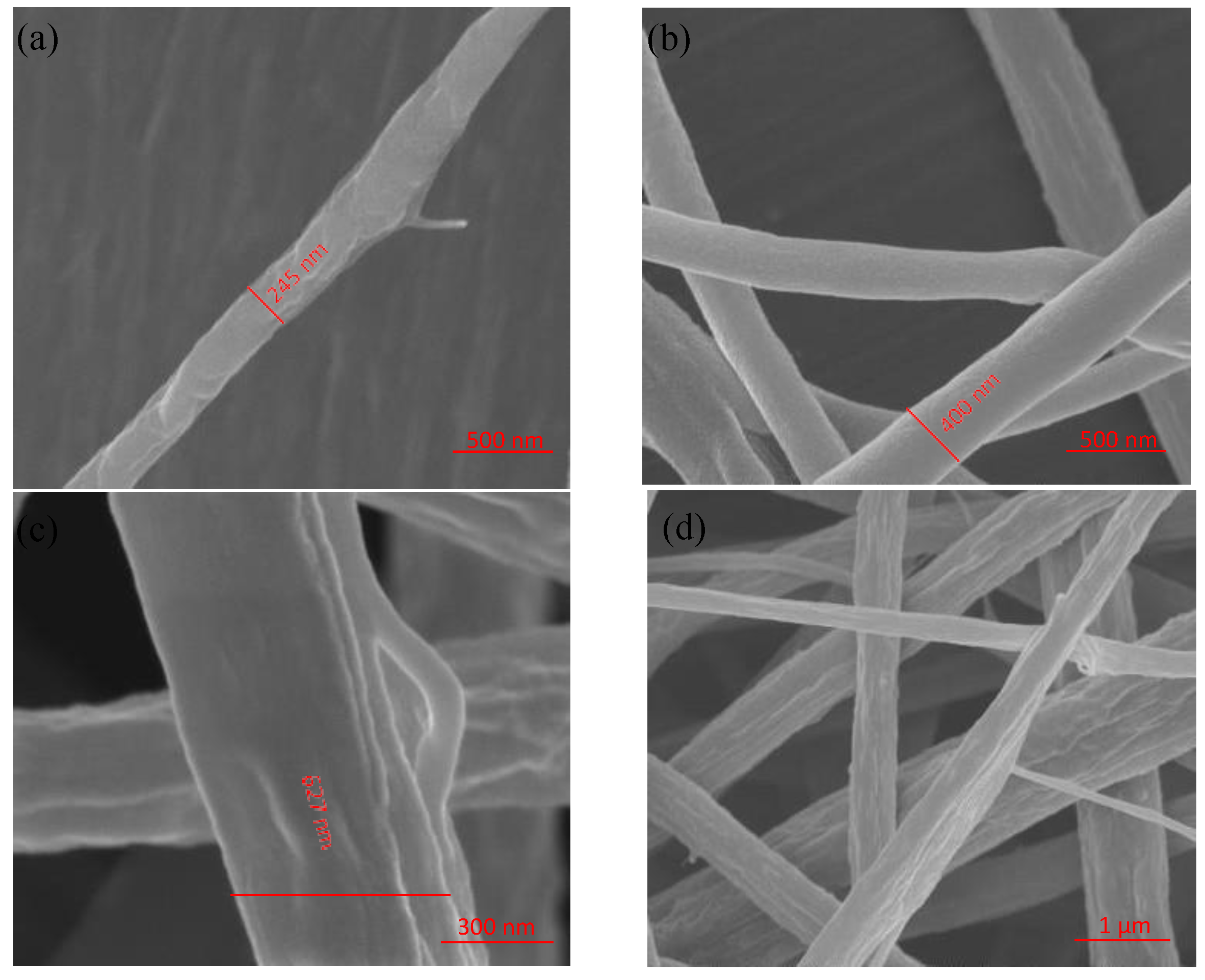
The electrospun nanofibers are visually inspected by employing FE-SEM (
Figure 1). The diameters of individual nanofibers are measured for each electrospinning voltage and tabulated in
Table 1. The effect of drum-speed on nanofiber diameters is also studied and the results are tabulated in
Table 2.
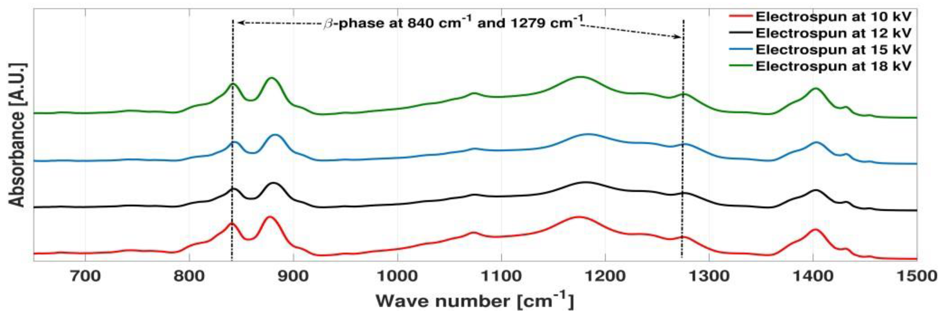
The effect of electrospinning parameter on the percentage of piezoelectric β-phase is studied using FTIR spectroscopy (
Figure 2). The fraction of piezoelectric β-phase for different electrospinning voltage calculated from the FTIR spectral plots using Beer-lambert formula [
4] is tabulated (
Table 3). A gradual increase in the fraction of β-phase: F(β) is observed in the electrospinning voltage range 12–18 kV. This can be explained by the fact that electrospinning process causes mechanical stretching and in-situ electrical poling simultaneously. Thus, increasing of electrospinning voltage leads to enhanced stretching and poling which aids the process of phase transformation from non-piezoelectric α-phase to piezoelectric β-phase [
4].
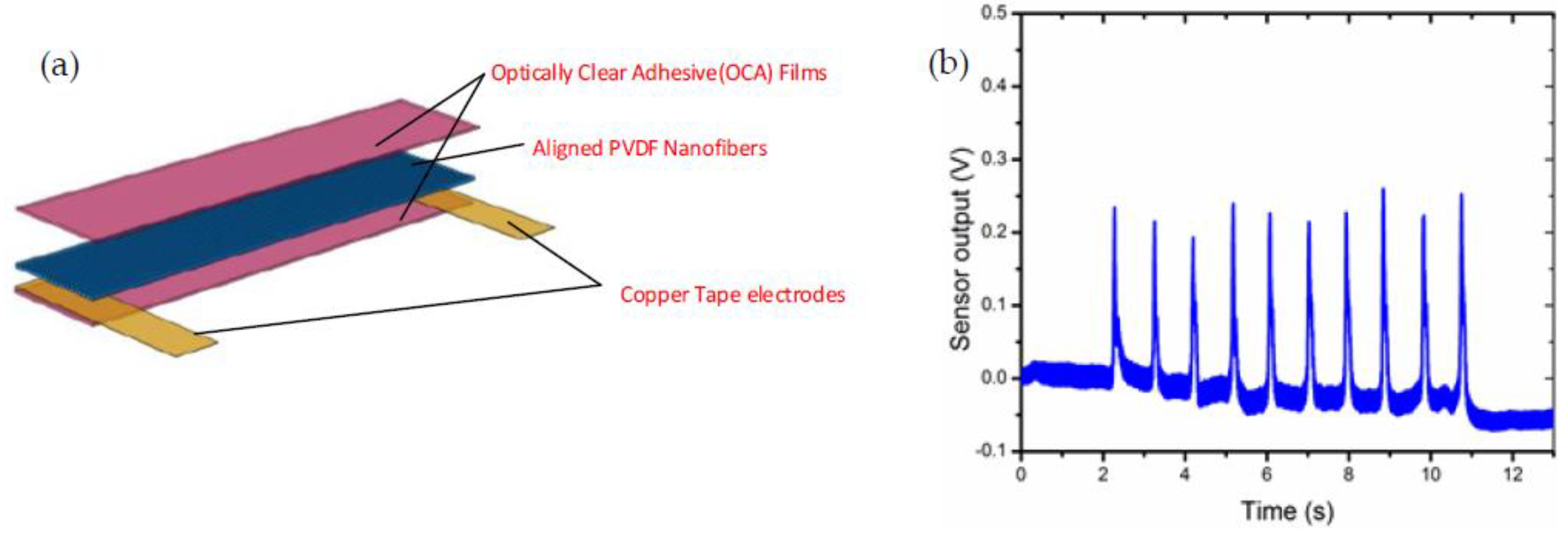
The optimized electrospinning recipe is used for fabricating uniform and well-aligned nanofiber web on an aluminum foil substrate, which is then transferred to an optically clear adhesive (OCA) film. Another OCA film is placed on top of the nanofiber web and pressed to seal the top and bottom OCA films, thus sandwiching the PVDF nanofiber web in between them forming a membrane. A series of conducting copper tapes are mounted on both sides of the PVDF membrane, which form the contact pads for each sensor. The
Figure 3a shows the schematic representation of the device fabrication. The fabricated PVDF energy harvesting membrane is subjected to a series of tapping tests and the open-circuit voltage thus generated is recorded using a national instrument data acquisition card (NI-DAQ) (at a sampling rate of 1 kHz). The following plot (
Figure 3b) shows the open-circuit voltage generated by the energy harvesting membrane when subjected to tapping tests at 1 Hz frequency. A maximum voltage output of 250 mV is observed in case of the tapping test.
4. Conclusions
In this work, a systematic study to optimize the electrospinning process for fabricating a piezoelectric PVDF-based flexible energy harvester is demonstrated. The piezoelectric β-phase content in the nanofiber bundles is demonstrated to have been maximized by increasing the electrospinning field voltage. Both, field voltage and rotating collector speeds are shown to affect the nanofiber morphology directly. Finally, a tapping test is conducted to show the energy harvesting capability of such nanofiber bundles when subjected to oscillatory stimulus. Flexible sensors of the kind presented in this work could find applications in wearable devices and smart skin applications.


