Proceeding Paper

A Gradiometric Magnetic Sensor System for Stray-Field-Immune Rotary Position Sensing in Harsh Environment †

1
Melexis, 2022 Bevaix, Switzerland
2
Melexis, 3980 Tessenderlo, Belgium
3
Melexis, 8900 Ieper, Belgium
*
Author to whom correspondence should be addressed.
Presented at the Eurosensors 2018 Conference, Graz, Austria, 9–12 September 2018.
Proceedings 2018, 2(13), 809; https://doi.org/10.3390/proceedings2130809
Published: 13 December 2018
(This article belongs to the Proceedings of EUROSENSORS 2018)

Abstract

:
Contactless magnetic position sensors are used in countless industrial and automotive applications. However, as a consequence of the electrification trend the sensors can be exposed to parasitic magnetic stray fields, and their desired robustness may be compromised. In this paper we publish for the first time how this challenge is addressed and constructively solved using a complete paradigm change leaving conventional magnetic field measurement behind and entering into the realm of magnetic field gradient measurement. Our novel sensor system consists of an integrated Hall sensor realized in 0.18 μm CMOS technology with magnetic concentrators and a four-pole permanent magnet. The intrinsic angular accuracy was assessed comparing the rotary position of the permanent magnet with the sensor output showing angle errors below 0.3°. Additional end-of-line calibration can be applied using built-in memory and processing capability to further increase the accuracy. Finally, we demonstrate the immunity against stray fields of 4000 A/m which led to errors below 0.1°, corresponding to 0.06% of the sensors fullscale angular range. In conclusion, this novel sensor system offers a compact and flexible solution for stray-field immune rotary position measurement in harsh environment.

1. Introduction

Magnetic sensors in general and magnetic position sensors in particular are increasingly popular means for manifold measurement tasks in industrial, automation, robotics, consumer, and automotive applications [1]. Their strength is the contactless, compact, and cost-effective position sensing nearly free from wearout and aging effects. In addition, magnetic vector position sensors feature thermal stability and are therefore suitable for harsh environment [2].
Modern vehicles however, with their electric drives, current flow between batteries, power inverters, and motors, as well as wireless charging induce parasitic magnetic fields [3]. This represents a tough challenge for conventional magnetic position sensors as the accuracy may be compromised by the parasitic fields [4] which not unlikely reach values up to 20 kA/m.

2. Concept

In contrast to conventional magnetic position sensors our novel sensor system exploits the inplane magnetic flux density gradients therefore being robust against uniform external magnetic fields. The system consists of a four-pole permanent magnet and an integrated CMOS Hall sensor with integrated magnetic concentrators [5], as shown in Figure 1a.
The four-pole permanent magnet can be based on various basic shapes, e.g., disk or ring shapes. Its alternating magnetization along the axial direction produces the desired in-plane flux density gradients ∂Bx/∂x, ∂By/∂y, ∂Bx/∂y, ∂By/∂x under the center of the magnet. At the same time the three components of the magnetic flux density vector Bx, By, Bz disappear.
Henceforth the useful flux density gradients are sensed by the CMOS Hall sensor microsystem consisting of eight circularly arranged Hall elements H0...H7 and magnetic concentrators. The combination of the raw signals VH0...VH7 with alternating signs, as shown in Figure 1b is a measure for the in-plane flux density gradients and simultaneously eliminates the impact from parasitic stray fields of arbitrary direction and intensity. As a result, we obtain the quadrature sensor signals C = VH0VH2 + VH4VH6 and S = VH1VH3 + VH5VH7 representing cos(2α) and sin(2α), respectively, having naturally a phase shift of 45°, as shown in Figure 1c.

3. Materials and Methods

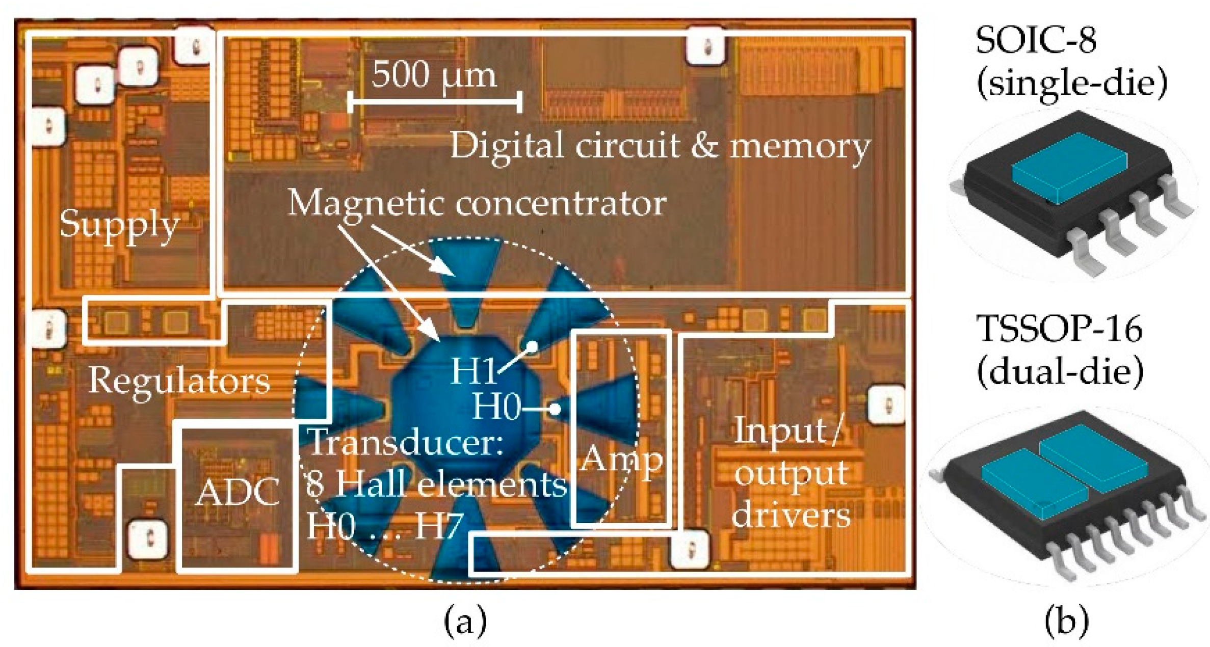
The Hall sensor microsystem was realized in a standard 0.18 μm CMOS technology with advanced circuitry for biasing, Hall read-out, and signal processing [6]. The eight Hall elements arranged on a virtual circle with a radius of 250 μm are complemented with 23-um-thin magnetic concentrators. An optical micrograph of the sensor microsystem is shown in Figure 2a.
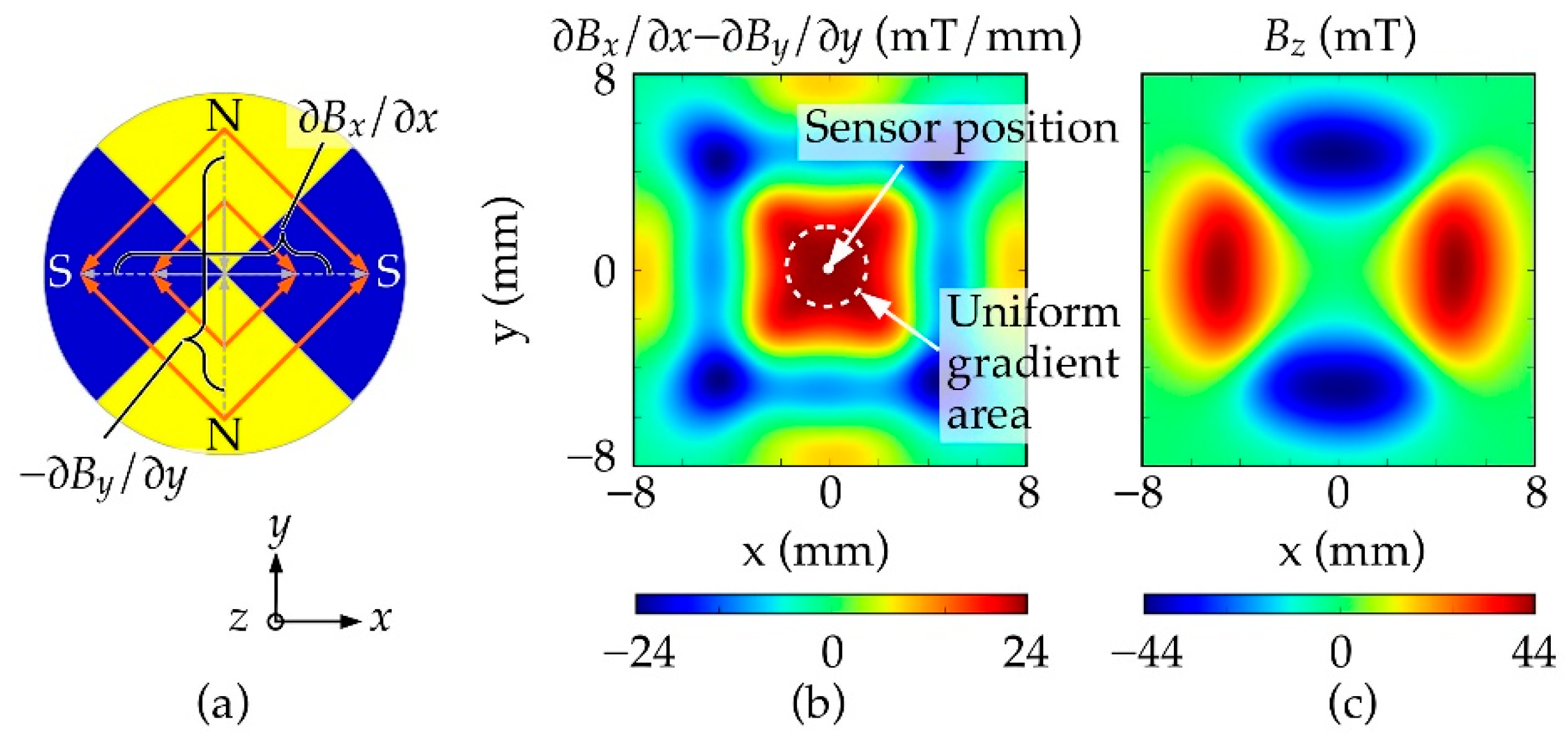
A particular feature of the novel sensor system is the use of a four-pole permanent magnet and its resulting flux density gradients, as illustrated in Figure 3a. Despite the fact that a great variety of magnet shapes and sizes can be used, we show results obtained from a ring-shaped magnet with an outer diameter of 14 mm, inner diameter of 5 mm and a thickness of 3.5 mm. This injectionmolded magnet is made of anisotropic bonded ferrite material and magnetized axially, i.e., in directions parallel and anti-parallel to the rotation axis. The resulting in-plane flux density gradient G = ∂Bx/∂x − ∂By/∂y and the out-of-plane flux density Bz are shown in Figure 3b,c, respectively, for a vertical distance (airgap) of 1.5 mm.

4. Results

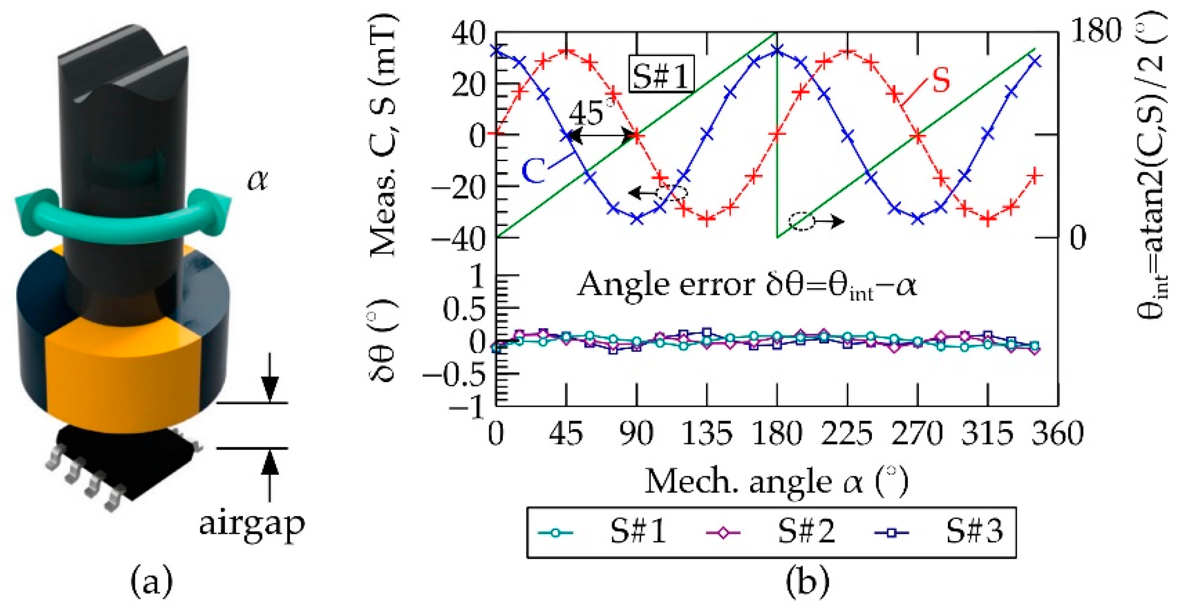
The sensor microsystem was exposed to the rotation of the four-pole magnet at various mechanical angles α between 0° and 360°, as schematically shown in Figure 4a. For a flux density gradient of G = 20 mT/mm signal amplitudes of about 33 mT were measured, being the product of Hall plate lateral distance and magnetic gain of the concentrator. Hence, a magnetic concentrator gain of gC = 0.83 mm was reached. Comparing the sensor’s detected angle θint to the mechanical reference α showed deviations δθ lower than 0.3°. This represents the intrinsic accuracy of the position sensor system without any post-processing nor trimming whatsoever. The measured signals and angle errors are shown in Figure 4b.
Finally, the stray-field-immunity was assessed by measuring the sensor’s angular position θint for various directions of the parasitic stray field, as schematically illustrated in Figure 5a. Stray fields with magnitudes of 20,000 A/m and 4000 A/m were applied, which led to angle errors δθ below 0.5° and 0.1°, respectively, as shown in Figure 5b. Therefore, the error at 4000 A/m strayfield-exposure was found to be as low as 0.06% of the sensors fullscale range of 180°. Further details are unveiled in our companion article [7].

5. Discussion and Conclusion

We presented a novel absolute rotary position sensor system based on an integrated Hall magnetic gradiometer and a four-pole permanent magnet. In contrast to the existing and ubiquitously applied magnetic position sensors [1], our sensor measures the in-plane magnetic field gradients and is therefore inherently insensitive to parasitic magnetic stray fields. In-depth experimental characterization revealed intrinsic angle errors below 0.3° and stray-field (4000 A/m) related errors typically below 0.1°. Overall, the solution outperforms the state of the art [7].

Acknowledgments

The authors would like to thank their colleagues for the fruitful collaboration and their constant support and commitment to realize and industrialize this solution.

Conflicts of Interest

The authors declare no conflict of interest.

References

  1. Granig, W.; Hartmann, S.; Köppl, B. Performance and Technology Comparison of GMR Versus Commonly used Angle Sensor Principles for Automotive Applications; SAE Technical Paper 2007-01-0397; SAE International: Warrendale, PA, USA, 2007. [Google Scholar] [CrossRef]
  2. Hiligsmann, V.; Riendeau, P. Monolithic 360 degrees rotary position sensor IC [automotive applications]. In Proceedings of the IEEE SENSORS, Vienna, Austria, 24–27 October 2004. [Google Scholar] [CrossRef]
  3. Karabetsos, E.; Kalampaliki, E.; Tsanidis, G.; Koutounidis, D.; Skamnakis, N.; Kyritsi, T.; Yalofas, A. EMF measurements in hybrid technology cars. In Proceedings of the 6th International Workshop on Biological Effects of Electromagnetic, Bodrum, Turkey, 10–14 October 2010. [Google Scholar]
  4. Schneider, D.; Urban, M. Magnetic Position Sensors and Stray Field Interference; AMS AG: Premstätten, Austria, 2014. [Google Scholar]
  5. Schott, C.; Racz, R.; Huber, S. Smart CMOS Sensors with Integrated Magnetic Concentrators. In Proceedings of the IEEE SENSORS, Irvine, CA, USA, 30 October–3 November 2005. [Google Scholar] [CrossRef]
  6. Leroy, S.; Rigert, S.; Laville, A.; Ajbl, A.; Close, G.F. Integrated Hall-based magnetic platform for position sensing. In Proceedings of the ESSCIRC, 43rd IEEE European Solid State Circuits Conference, Leuven, Belgium, 11–14 September 2017. [Google Scholar] [CrossRef]
  7. Dupré, N.; Dubrulle, O.; Huber, S.; Burssens, J.-W.; Schott, C.; Close, G. Experimental Demonstration of Stray-Field Immunity beyond 5 mT for an Automotive-Grade Rotary Position Sensor. Proceedings 2018, 2, 763. [Google Scholar]
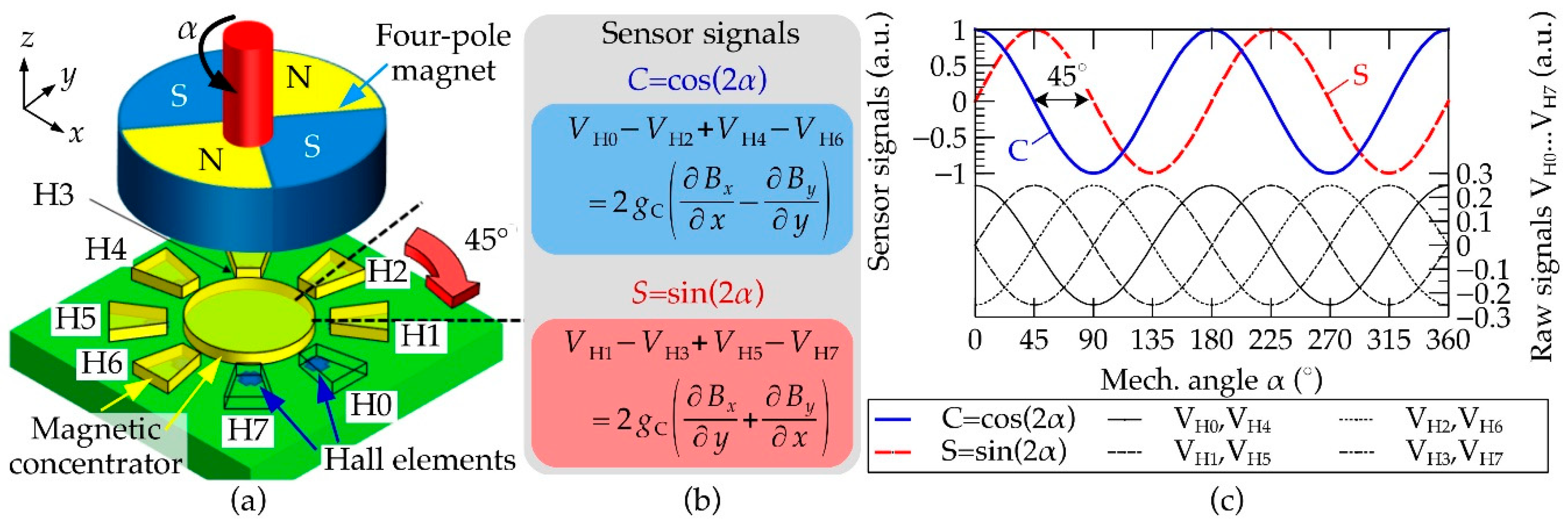
Figure 1. Concept of the rotary position sensor system. (a) The four-pole magnet provides in-plane flux density gradients to the sensing device consisting of eight circularly arranged Hall elements and a magnetic concentrator. (b) The in-plane flux density gradients in combination with the concentrator gain gC give rise to eight raw signals VH0...VH7 out of which the sensor signals C = VH0VH2 + VH4VH6 and S = VH1VH3 + VH5VH7 are composed, representing cos(2α) and sin(2α), respectively. (c) Calculated values of the raw signals and the sensor signals.
Proceedings 02 00809 g001
Figure 2. (a) Optical micrograph of the sensor microsystem implemented in a standard 0.18 μm CMOS technology. The eight circularly arranged horizontal Hall elements are complemented with an accurately structured 23-μm-thin magnetic concentrator [5] in order to exploit the in-plane magnetic field components. The integrated circuitry is discussed in-depth in [6]. (b) assemblies into SOIC-8 and TSSOP-16 molded plastic packages for the single-die and redundant, side-by-side dual die versions, respectively.
Proceedings 02 00809 g002
Figure 3. (a) Schematic illustration of the flux density gradients under a four-pole magnet. (b) Measured flux density gradient G = ∂Bx/∂x − ∂By/∂y and (c) magnetic flux density Bz at a vertical distance of 1.5 mm under a four-pole bonded ferrite ring magnet with an outer diameter of 14 mm, an inner diameter of 5 mm, and a thickness of 3.5 mm. The flux density gradient of G = 24 mT/mm representing the sensor’s useful field source was found to be uniform in a 4 mm by 4 mm large area.
Proceedings 02 00809 g003
Figure 4. (a) Schematic representation of the measurement setup. (b) Measured sensor signals C and S of sample S#1 showing an amplitude of about 33 mT at a field gradient of G = 20 mT/mm. Consequently, a magnetic concentrator gain of gC = 0.83 mm was found. As expected, the calculated angular position θint was confirmed to alternate twice for a full 360° rotation and its deviations δθ from the mechanical reference α were found to be below 0.3°. For the sake of legibility, results of three samples S#1, S#2, and S#3 are shown.
Proceedings 02 00809 g004
Figure 5. Impact of the applied parasitic stray field on the measured angle. (a) Sample S#1 was exposed to stray fields of 4000 A/m and 20,000 A/m from various directions φ and ψ. (b) The observed typical changes in the measured angle δθ were below 0.1° and 0.5°, respectively.
Proceedings 02 00809 g005
Publisher’s Note: MDPI stays neutral with regard to jurisdictional claims in published maps and institutional affiliations.