1. Introduction
For the maintenance of manufacturing plants, macroscopic elapsed-hour counters often roughly indicate upcoming service requirements. Usually the maintenance intervals are based on empiric data, not covering individual machine and component-specific wear.
More focused maintenance routines can be achieved by the surveillance of the critical components using autonomous sensors. This allows to register unusual operating conditions, such as vibrations, shocks or the violation of temperature limits. However, the integration of such sensors is often limited by the need of sufficient electrical energy. Since constant environmental energy flow is needed for effective energy harvesting, these systems are not suitable for applications with unstable conditions. As an alternative to energy harvesting, new sensor concepts focus on systems where no electrical energy is needed at all for sensing and storing of the measurement results. In many cases, only the violations of off-limit conditions with corresponding high signal amplitudes are of interest. Therefore, energy can be absorbed directly from these intense signals to trigger a micromechanical system, which senses and saves the measurement results non-electrically.
In [
1] we presented the basic idea of a 2-bit micromechanical binary counter realized in surface MEMS. Using a ratcheting mechanism, mechanical impulses at the system’s entrance are converted into mechanically saved binary counts. In this contribution, we present an optimized version of the counter, featuring a MEMS-based digital-to-analog converter, that allows to convert mechanically saved binary code into an analog voltage. The concept presented, allows to mechanically count any physical threshold violation without the need of electrical energy. For an electronical read-out of the mechanical storage, the saved binary code is converted into an analog voltage, making the system suitable for the connection to RFID interfaces.
2. System Design
2.1. Binary Counting Mechanism
The micromechanical binary counter is based on a two-dimensional mechanism, allowing its fabrication in surface MEMS technology.
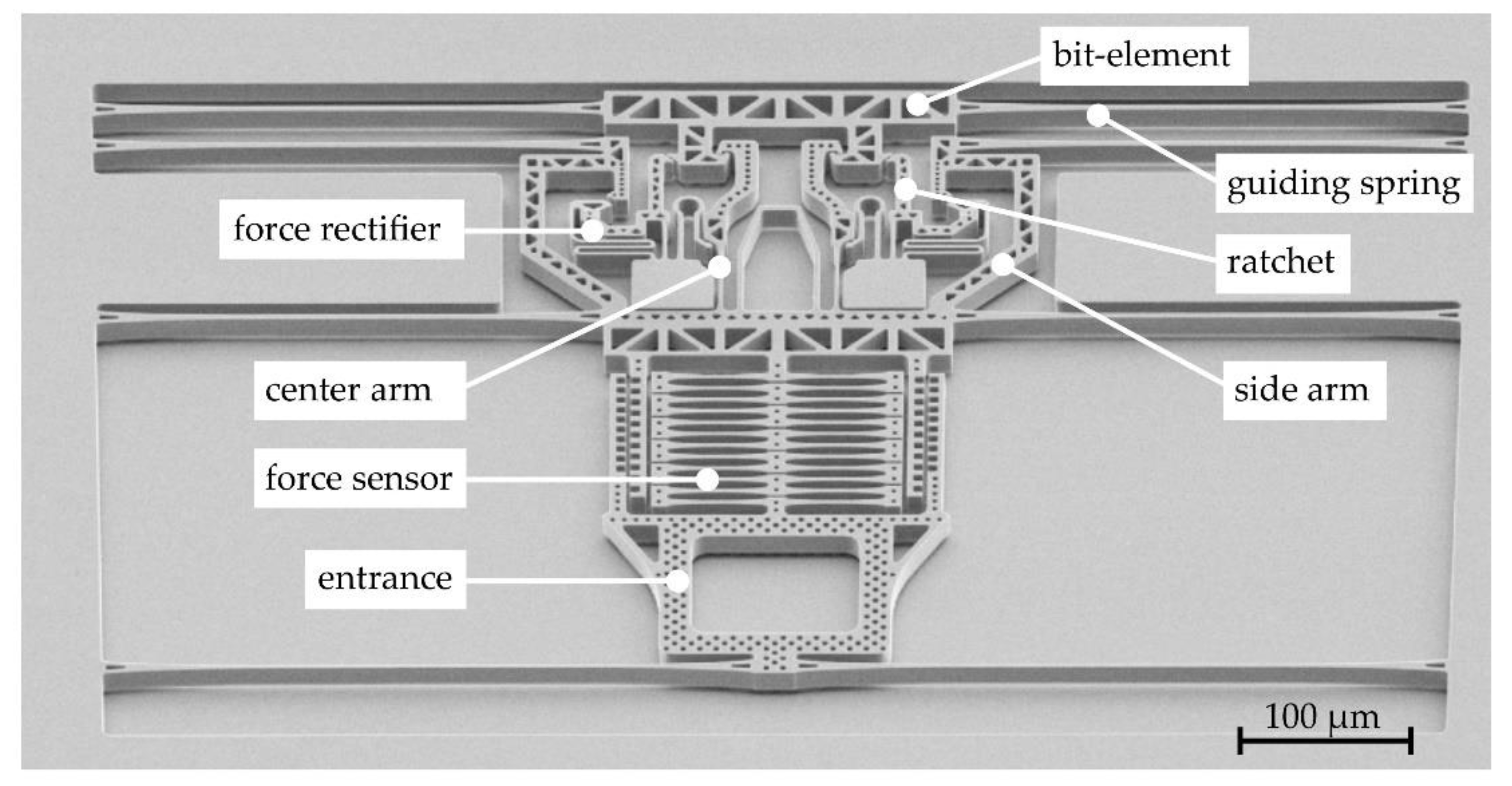
Figure 1 shows a 1-bit system with the main mechanical components. By connecting multiple of these bi-stable elements (referred to as
bits) in a serial arrangement, an n-bit mechanical counter can be created. Each bit can be set in two stable states, namely a low (0) and a high (1) state. The low state is defined as the state whereas the
guiding springs at the
bit-element are deflected and the
ratchet is hooked to the
bit-element.
To increment the counter, a mechanical impulse at the system’s entrance, such as a mechanical shock is needed. The least significant bit (LSB) connected directly to the entrance (bit 0) is then provoked to change its state from low (0) to high (1). If, for a next impulse, the LSB changes its state again from high to low, the subsequent bit in the serial arrangement is triggered to change its state, too. Similar to a shifting register, impulses at the system's entrance are shifted from the LSB through the serial arrangement to the most significant bit allowing a mechanical count on a binary basis.
For a better understanding of the mechanical transition process from one state to the next one, a schematic description of the transition from 0-0 to 1-0 for a 2-bit counter is provided in
Figure 2.
2.2. MEMS-Based Digital-to-Analog Converter
MEMS-based digital-to-analog converters (DAC) are known for converting electrical binary code into a mechanical displacement or force [
2,
3]. The inverse conversion from a mechanical binary signal to an analog electrical signal is presented in this contribution.
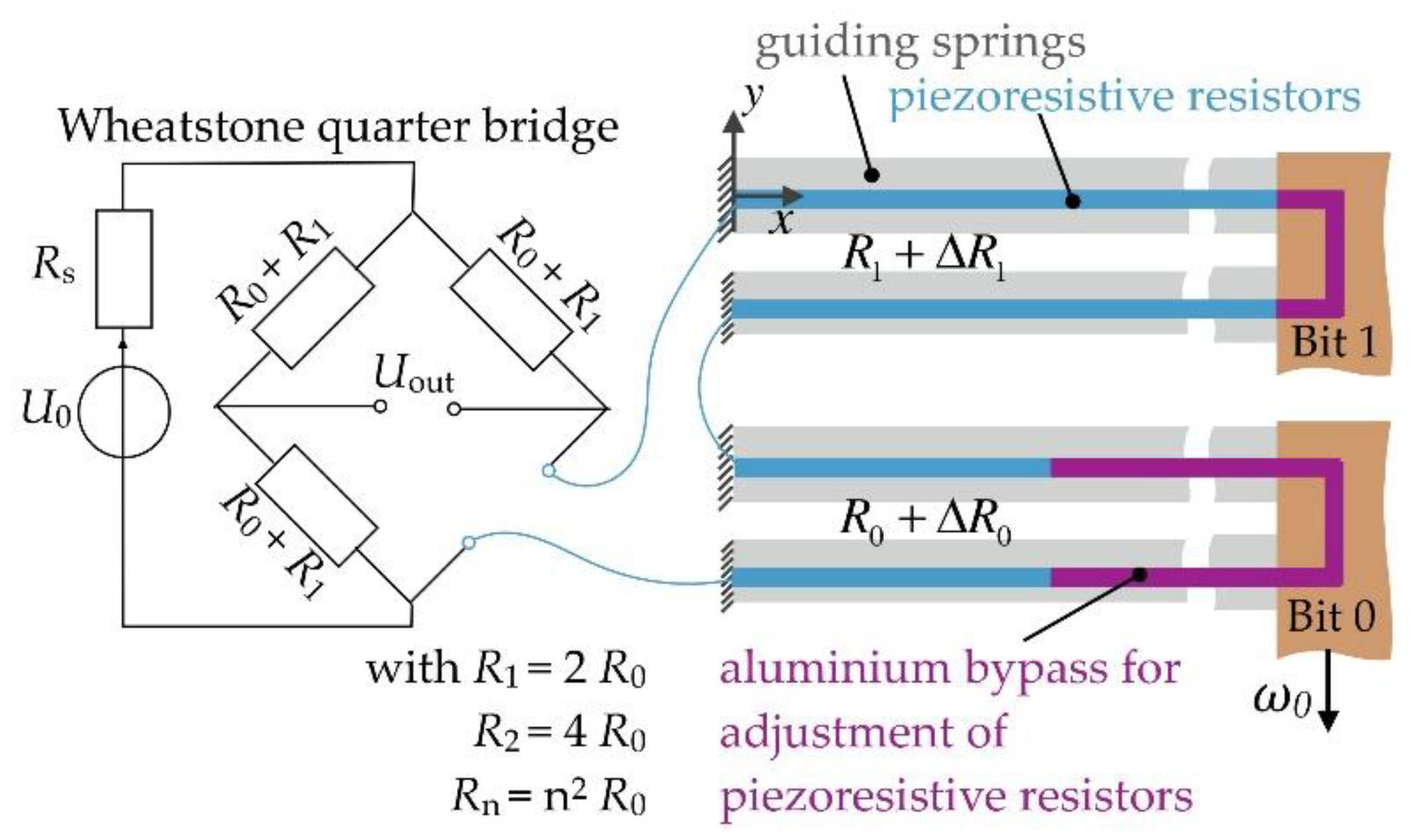
The working principle of the cross-domain DAC is illustrated in
Figure 3. Piezoresistive strain gauges with different resistance values are used as transducers. The strain gauges are positioned at the guiding springs of each bit. Depending on the bit-state, the correlating strain gauge can be either strained or relaxed.
To eliminate cross-sensitivity to temperature changes, the strain gauges are arranged in a quarter Wheatstone bridge. The basic resistances of each strain gauge strictly depend on the associated bit position
i, which can be determined by:
Note that the value of the reference resistors within the Wheatstone bridge is the combined resistance value of all strain gauges that are connected in series.
Assuming that the maximum deformations
εt and the gauge factor
k of all strain gauges are identical, the magnitude of the resistance change ∆
Ri depends only on the bit-position
i, due to the associated basic resistance:
The ratio of the bridge voltage
Uout to the input voltage
Uin and therefore the digital-to-analog conversion law for the modified Wheatstone bridge can be easily determined by:
Here
takes the Boolean status 0 or 1 of the respective bit. Since for the binary counter, strained guiding springs indicate the low state, the value for
z needs to be negated first. This means that if the counter is set to the maximum binary count of 11…1, none of the guiding springs are strained, therefore
= 0, ∀𝑖 ∈ ℕ and
Uout becomes zero. For the 2-bit DAC as shown in
Figure 2, the status table is shown in
Table 1.
3. Experiment
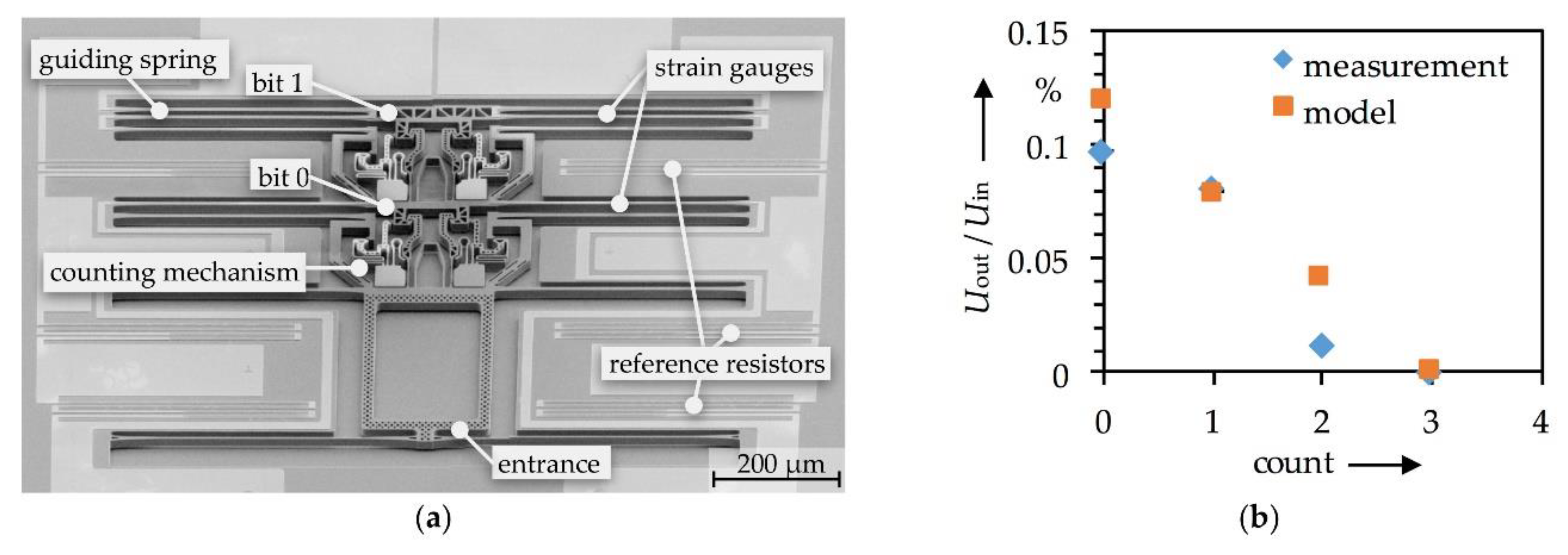
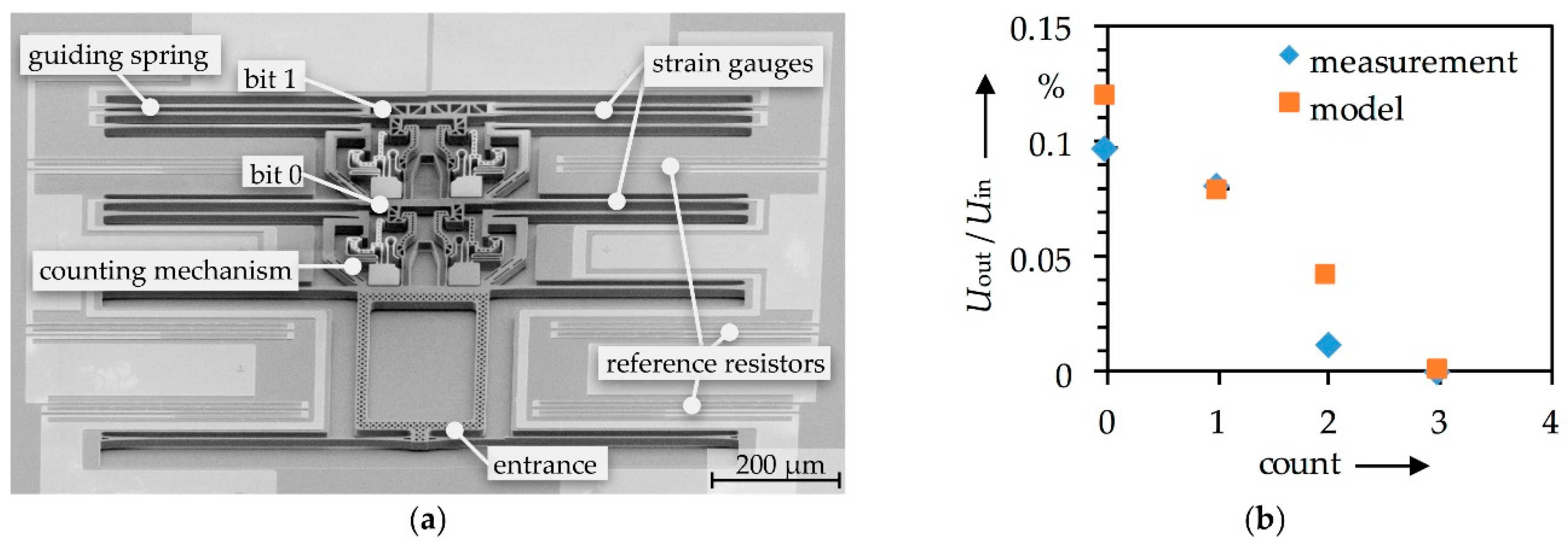
The microsystem, as shown in
Figure 4a, was fabricated utilizing a standard silicon-on-insulator substrate (SOI). For the realization of the piezo resistive strain gauges, P-doped polycrystalline silicon with a gauge factor of 15.8 were deposited by LPCVD.
For the electrical characterization, the output of the MEMS-DAC was connected to an instrumentation amplifier with an amplification factor of 100. The amplified signal was then analyzed using an oscilloscope. After adjusting the initial offset with the instrumentation amplifier, the counter was successively incremented manually with a tungsten needle clamped to a piezo linear stage.
Figure 4b shows the measured digital-to-analog conversion without amplification. The modelled values are obtained from Equations (2) and (3), assuming a deformation of
εt = 0.03% and a basic resistance of
R0 = 196 kΩ. The variation shown between the model and the measurement results at count 0 and 2 are assumed to be based on a variation of the total strain at the guiding springs of bit 0 and bit 1.
4. Summary and Conclusions
We presented a micromechanical binary counter which is suitable for counting physical threshold events by applying mechanical impulses at the entrance of the system. For the first time, we present a MEMS-based digital-to-analog converter integrated in a mechanical binary counter that allows to convert mechanically saved binary code into an analog voltage. With first experimental results the proof of principle for this concept of a cross-domain DAC was demonstrated.


