1. Introduction
Compared to the closed PAS described and simulated in [
1,
2], the open PAS described in this publication has a smaller size factor which makes it more attractive for mobile applications. The more compact nature of this sensor comes at the cost of an increased thermal coupling within the package which needs to be accounted for in the simulations to be able to accurately predict performance. At the same time, acoustic coupling at the microphone also plays an important role and needs to be modeled as well. The proposed co-simulation approach is a judicious combination of different software tools and gives the designer enough flexibility to cope with the impairments mentioned above.
A key step in the generation of a reliable system model is the validation against measurements performed in the lab on the target samples. To this end the thermo-acoustic and the photo-acoustic signals at the output of the microphone need to be extracted for several working frequencies of the infrared emitter and compared against the simulated values. Once the validation step is completed, the system models can be used to ensure that the performance accuracy of the sensor meets a given target when environmental conditions such as pressure, temperature or humidity change. Similarly, signal processing algorithms can be enhanced to be able to deal with noise and acoustic interference.
In the following Sections the sensor’s working principle and simulation approach will be described. Furthermore, several examples will be provided of how a calibrated system model can be used to explore algorithm, and system modifications which are often difficult to be reproduced in a lab environment.
2. Approach Description
The objective of this work is to develop simulation models that are able to reliably predict the behavior of an open PAS in various scenarios and for various choices of the key system parameters.
The working principle of an open PAS is outlined in
Figure 1a. Here the radiation of the infrared emitter is periodically chopped at a given frequency and then filtered with an optical filter which selects only those wavelengths at which CO
2 absorption can take place. The pressure variation originated in the absorption chamber is directly proportional to the CO
2 gas concentration and can thus be measured with a microphone placed in the same volume.
Our co-simulation approach is represented in
Figure 1b and it consists of State-of-the-Art and affordable tools which are popular in system modeling practice. More precisely, the core of our simulator is a specially pre-configured and extended version of the SIMetrix SPICE/Verilog-A environment. Scripting and interactive development of simulations and data-analysis, as well as plotting and reporting are supported using the widely-used and powerful Python scripting language.
As far as our application is concerned, the thermal behavior of the package is first characterized in terms of its building blocks (infrared emitter, optical filter, cavity and microphone), materials and geometry, and then mapped onto a SIMetrix SPICE schematic. Here, pairs of thermal resistors and capacitors are modeled in properly designed Verilog-A blocks representing the heat flowing through the different layers of the sensor and generating an additional pressure variation in the volume cavity. This additional pressure signal represents some sort of ‘noise’ which adds up to the pressure variation caused by the photoacoustic effect. The latter is described in a Python code which is provided with several key ingredients such as the absorption curve of the gas for the given temperature, pressure and humidity, the optical filter characterization, and the assumed optical path in the volume cavity.
In the sensor volume acoustic noise or interference and other coupling effects can occur and impact the final performance of the sensor. In our system simulation these disturbances are modeled depending on the specific usecase and applied to the acoustic port of the microphone output.
Finally the simulation output signals of our co-simulations are sampled and processed in Python where performance metrics are extracted and compared for different values of the system parameters (such as infrared emitter frequency, package sizes and geometry, gas concentrations, etc.).
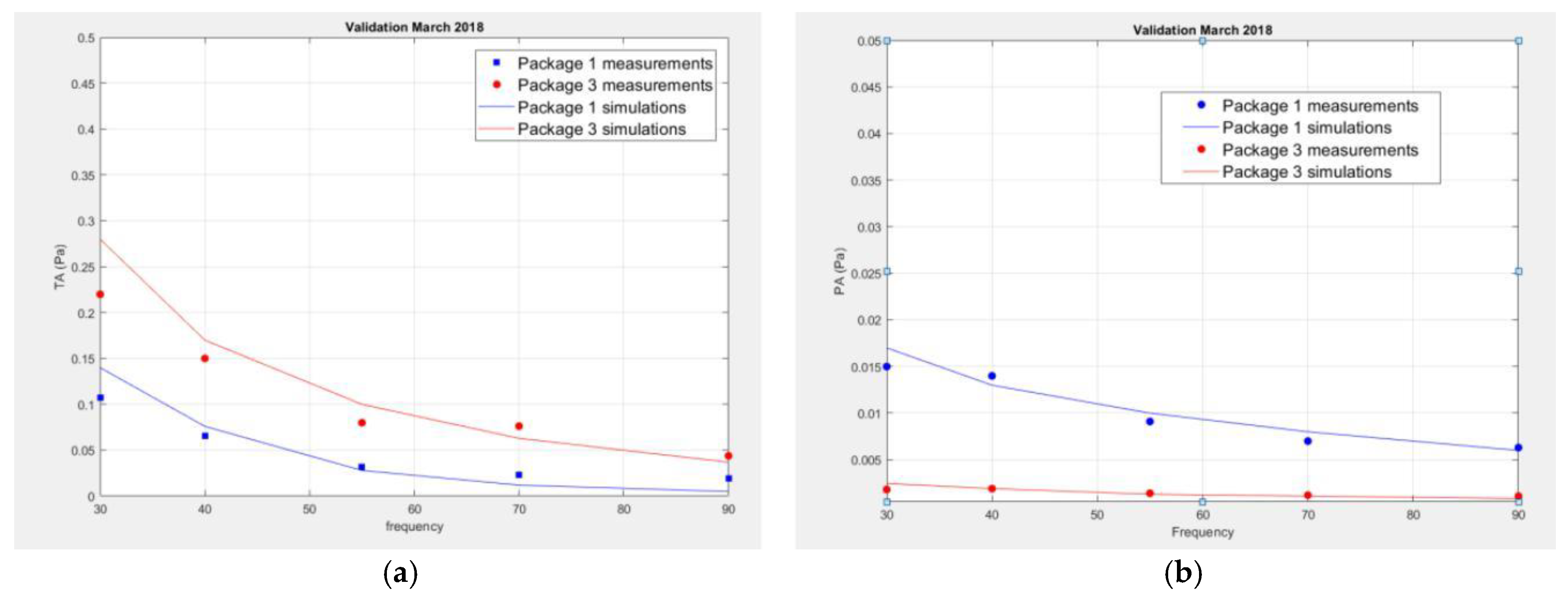
It is clear that, before using the proposed system models for algorithm explorations and further optimizations, a validation campaign needs to be carried out in order to verify that models can correctly predict the measured sensor behavior at least for the key system parameters and their ranges of interest. To obtain a good match an iterative procedure is often needed where different hardware options are tested and correlated among each other and models are then adjusted until the relative trends are correctly predicted and the absolute values of the signals are within an acceptable tolerance as shown in
Figure 2. Here we provide the amplitude of the thermo-acoustic (TA) and photo-acoustic (PA) signals for two package geometries and different infrared emitter frequencies. Simulation and measurements results match quite well and the proposed system models can be used for the explorations of use-cases that are difficult to reproduce in the lab as discussed in the next Section.
3. Exploration and Optimization with the System Model
As mentioned above an open PAS with its small form factor faces several challenges whose impact on the final estimation accuracy needs to be carefully evaluated. A validated system model can help explore those usecases that are difficult to be reproduced in the lab such as variations in the environmental conditions or the presence of various acoustic noise coupling effects.
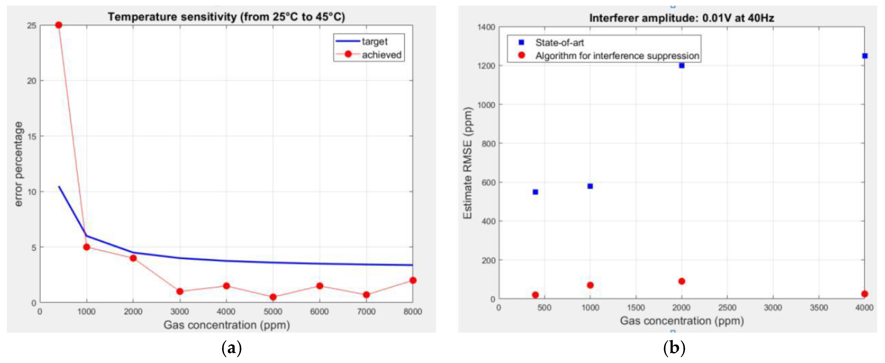
Figure 3a illustrates the behavior of the sensor when the temperature of the surrounding environment changes from the standard condition at which the sensor has been calibrated (25 °C) to a new higher value (45 °C). A change in the outside temperature (but also in the pressure or humidity) implies modifications to both the thermos-acoustic model—to account for changes in material properties such as heat capacity, viscosity and thermal conductivity—and to the photo-acoustic model – to account for changes in the gas absorption.
The relative error of the generic estimation algorithm is provided as the CO2 gas concentration increases from 400 to 8000 ppm. It is seen that, despite the increase in temperature, at concentrations ≥1000 ppm the accuracy requirement of 3% ± 30 ppm is still achieved. At lower concentration values a recalibration of the estimation algorithm will be needed based on a coarse estimate of the actual temperature. A similar analysis can be repeated for variations of the pressure and humidity values to assess the robustness of the system and to predict whether and how often the estimation algorithm needs to be recalibrated based on external measurements provided by other environmental sensors (e.g., a pressure or humidity sensor).
Another relevant aspect in the analysis of an open photoacoustic gas sensor is its behavior in the presence of acoustic noise coupling. Depending on the specific application (e.g., home or mobile), different scenarios can be defined and simulated, such as narrowband acoustic interferers, wind noise, vibrations and other noise profiles measured in typical environments such as offices, flats, halls and so on. To this end, a Verilog-A block implementing the spectrum of the selected noise scenario can be generated and coupled to the acoustic port of the microphone in the SIMetrix schematic.
In
Figure 3b we illustrate the effect of a narrowband interferer at the same frequency of the infrared emitter for different concentrations of the gas in ppm. While a state of the art algorithm will exhibit large estimation errors, new approaches can be devised thanks to the proposed system models so as to improve the accuracy of the sensor output.
4. Conclusions
In this contribution we have presented a new co-simulation approach for the system characterization of an open photoacoustic gas sensor which encompasses different physical quantities and various coupling effects.
Next steps are the evaluations of new sensor geometries and the incorporation of more physical effects into our system simulation combined with a continuous validation and refinement effort to improve the models accuracy in various realistic scenarios.


