Proceeding Paper

Highly Confined Love Waves Modes by Defects States in a Phononic Crystal Based on Holey-SiO2/ST-Cut Quartz Structure †

Univ. Lille, CNRS, Centrale Lille, ISEN, Univ. Valenciennes, UMR 8520 IEMN, LIA LICS/LEMAC, 59650 Lille, France
*
Author to whom correspondence should be addressed.
Presented at the Eurosensors 2018 Conference, Graz, Austria, 9–12 September 2018.
Proceedings 2018, 2(13), 729; https://doi.org/10.3390/proceedings2130729
Published: 13 December 2018
(This article belongs to the Proceedings of EUROSENSORS 2018)

Abstract

:
We investigate the properties of highly confined Love modes in a phononic crystal based on an array of holes made in SiO2 deposited on ST-cut Quartz substrate. An optimal choice of the geometrical parameters of the holes enables us to obtain wide stop-bands frequency for shear wave’s modes. The introduction of defect by removing lines of holes leads to nearly flat modes within the band gap and consequently paves the way to implement advanced design of electroacoustic filters and high-performance cavity resonators based on shear wave modes. The calculations are performed using finite element method based on the commercial software (COMSOL-Multiphysics). For transmission spectra, piezoelectric excitations are applied by considering the interdigital transducers, with results corroborating well the band structure predictions and the position of defects modes within the band gap.

1. Introduction

Phononic crystals (PnCs) are widely investigated for their potential applications in various areas. The introduction of defects into PnC is at the origin of multiple applications such as waveguide, filter, cavity and multiplexer [1,2,3]. The applications of sensors, especially the bio-sensors, are based on the Love waves and antisymmetric Lamb waves, which are compatible with the liquid environment [4,5]. However, Lamb waves propagate on the extremely thin slabs, making them comparably fragile and therefore difficult to be manipulated. Whereas Love waves, a shear horizontal (SH) polarized surface acoustic waves (SAW), exist in the guiding layer deposited on a semi-infinite substrate, which guarantees both the confinement of the energy and the robustness of the device. In recent years, the band-gap effect of PnC on Love waves has been reported [6], the studies concern the improvement of Q-factor of resonator surrounded by PnC. Nevertheless, the exploitation of Love waves interacting with the defect states in PnC remains to be investigated. In this work, we first demonstrated the defect modes for Love waves propagating in the PnC.

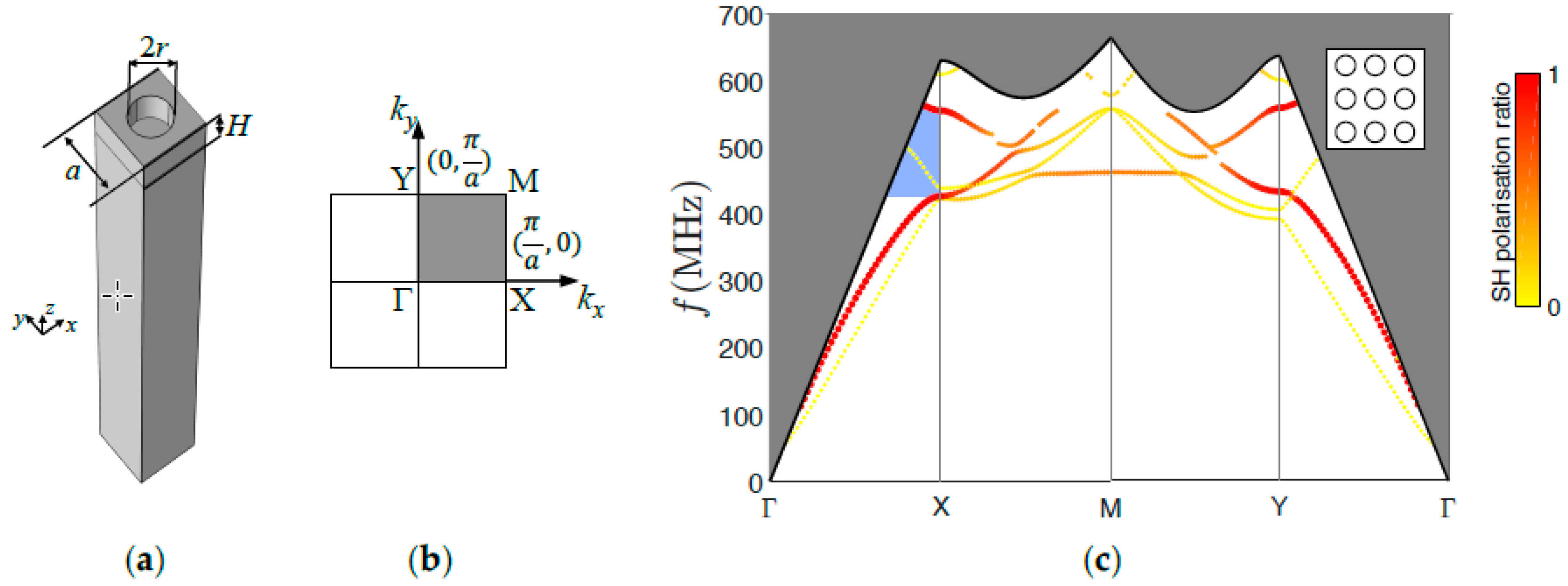
2. Materials and Methods

The guiding layer of Love waves is a H = 2.4 µm height of silica (ρ = 2200 kg/m3, E = 70 GPa, v = 0.17) covering a 90ST-cut quartz substrate (Euler angles = (0°, 47.25°, 90°), LH 1978 IEEE), which has been rotated 90 degrees around the z-axis from the ST-cut quartz, for a fast SH wave (5000 m/s) can be generated. The shear wave velocity in the silica film is 3438 m/s, less than that in 90ST-cut quartz substrate, indicating the existence of Love waves. The cylindrical holes in the silica film have a radius of r = 0.8 µm. The period of square array or the lattice constant is a = 4 µm. The air hole is chosen because of its strong contrast in density and elastic constants with regard to the silica. A unit cell of the PnC constructed in COMSOL, showing in Figure 1a, is employed to calculate the dispersion curves or the band structure. Floquet periodic boundary conditions are applied along the x and y directions. The Love waves propagate along the x-axis (y-axis of ST-cut quartz) where the electromechanical coupling of Rayleigh type SAW to the generated electric field is zero [6]. The first Brillouin zone (BZ) of the PnC is shown in Figure 1b, the irreducible BZ is a square bounded by Γ-X-M-Y-Γ. The surface of PnC coincides with the plane z = 0. The wavelength normalized energy depth (NED) is calculated to select the surface modes for which is less than 1.
NED = D 1 2 T i j S i j * ( z ) d x d y d z λ D 1 2 T i j S i j * d x d y d z
where 𝑇ij is the stress and 𝑆ij the strain. The star symbol (*) signifies the complex conjugate. 𝒟 denotes the whole domain of unit cell. 𝜆 is the wavelength. The NED can well select the surface modes with a relatively large wave vector k (below the dispersion relation of the SH wave in the substrate). For the modes with a relatively small k, 𝜆 is fixed to 2𝑎. The ratio of SH polarization is calculated to distinguish the Love waves and the Rayleigh waves.
SH   ratio = D u S H u S H * d x d y d z λ D ( u x u x * + u y u y * + u z u z * ) d x d y d z
where 𝑢x, 𝑢y and 𝑢z are respectively the displacement along the x, y, z direction. 𝑢SH is the SH displacement component that can be expressed as 𝑢x cos 𝜃 − 𝑢x sin 𝜃, which is perpendicular to the wave vector 𝒌. 𝜃 is the angle between 𝒌 and the y-axis with tan θ = k x k y .
The resonator is realized by removing one lines of holes along the y direction in the lattice of PnC, forming a cavity perpendicular to the propagating direction. A supercell is constructed and shown in Figure 2a, with 𝑊 the width of the cavity. Periodic boundary condition is applied along y direction. The band structure of Love waves in the defect-containing PnC is calculated along Γ-X.
The transmission spectra are realized by simulating a SAW device consisting of two parts of aluminum inter-digital transducers (IDTs) and a PnC located between the IDTs, with periodic boundary condition applied along y direction. The height of IDTs is hIDT = 200 nm. The IDTs are constructed on the piezoelectric quartz surface to generate the electric field. The model is surrounded by perfect matched layers (PMLs) for absorbing the undesired reflections from the boundary. One of the IDTs performing as a transmitter are given a harmonic voltage signal, with an amplitude of 1 V. The IDTs on the other side perform as a receiver. This frequency response is then normalized by that of the matrix (without PnC) to show the transmission loss contributed by the PnC only. The width of the fingers of IDT 𝐿IDT has been updated for every frequency in the spectrum according to the relation L I D T = λ 4 = υ 4 f . 𝜐 is the velocity of Love waves for 𝐻 = 0.6𝑎, resulting from the basic dispersion relation of Love waves.

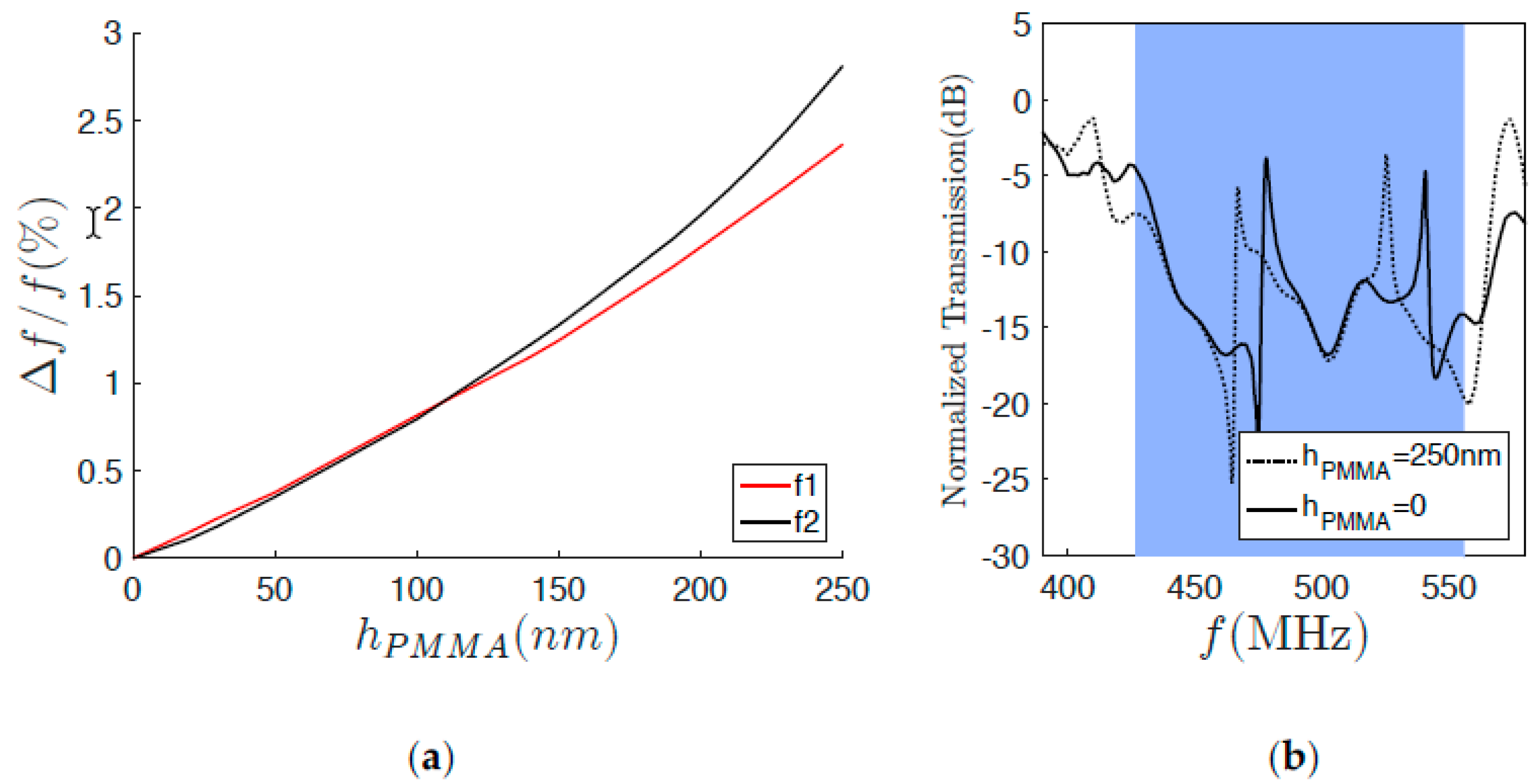
3. Results and Discussion

The complete band structure is shown in Figure 1c. The gray part is the radiation zone, where the waves diffuse to the volume (the bulk waves). The black line is the dispersion relation of the SH waves (here the fast shear waves) in the substrate, according to υ = 2 π f k . Each curve denotes a surface polarization mode. With the change of propagating direction, certain modes disappear as they start to diffuse into the volume. The colors of the modes are determined by their SH ratio. The red modes have a large SH ratio, indicating the Love modes. The more yellow the modes, the closer they are to the Rayleigh modes. The orange color implies a coupling between the Love modes and the Rayleigh modes. In the Γ-X direction, the Love waves are not coupled to the Rayleigh waves, showing a large band gap ranged from 426.8 to 555.5 MHz between the two Love modes. Due to the exclusive generation of Love waves by the generated electric field along the x-axis, hereafter we will only consider the Love modes propagating in the x direction.
The band structure of Love waves in the defect-containing PnC is calculated along Γ-X and is shown in Figure 2b. The cavity width is set to be 𝑊 = 5𝑎. It is found that two new flat modes, referred as defect modes or cavity modes, appear inside the previously observed band gap, respectively at 479.5 MHz and 538.5 MHz. This band structure is attributed to a coupling between the cavity and the perfect PnC.
Figure 2c shows the normalized transmission spectra with and without the cavity on the PnC, calculated with 4 holes on each side of the cavity (𝑁PnC = 4). Without defect, the attenuation in the predicted band gap zone appears clearly. The normalized transmission spectrum for the PnC containing the cavity shows correspondent peaks at 478 MHz and 540.6 MHz insides the band gap zone, consistent with the predicted resonant frequencies. The two flat cavity modes give rise to the highly confined transmission peaks. This means the cavity enables the propagation of waves that are otherwise forbidden in the perfect PnC. The displacement field of the cavity modes are shown in Figure 2d. The Love waves are well confined at the surface (the silica guiding layer). The displacements are concentrated in the cavity and attenuated at both ends.
PMMA film is then added on the cavity. Figure 3a shows the sensitivity Δ f f of the resonator calculated for different PMMA thickness hPMMA. 𝑓 is the resonant frequency of the cavity modes without the PMMA film, while Δ𝑓 is the difference between the resonant frequencies with and without the polymer. Transmission spectra of the resonator with and without the PMMA film shown in Figure 3b exhibit shifts for the two peaks, showing the possibility of displacing the resonant frequencies of cavity modes by modifying the thickness of the polymer.

4. Conclusions

In summary, we have presented the evidence of a partial band gap for Love waves propagating in a PnC consisting of holey square arrayed silica film on a 90ST quartz. Cavity modes in the phononic band gap for Love waves are first demonstrated by removing lines of holes from the guiding film. The transmission peaks of cavity modes in the band gap of perfect PnC is attributed to the appearance of new flat modes in the band structure. The transmission spectra are proved to be consistent with the band structure predictions. PMMA film added on the cavity proved the possibility of manipulation on the position of transmission peaks. This study could be used for Love waves based potential applications of PnC devices.

Conflicts of Interest

The authors declare no conflict of interest.

References

  1. Khelif, A.; Choujaa, A.; Benchabane, S.; Djafari-Rouhani, B.; Laude, V. Experimental study of guiding and filtering of acoustic waves in a two dimensional ultrasonic crystal. Z. Krist. 2005, 220, 836–840. [Google Scholar] [CrossRef]
  2. Jin, Y.; Fernez, N.; Pennec, Y.; Bonello, B.; Moiseyenko, R.P.; Hémon, S.; Pan, Y.; Djafari-Rouhani, B. Tunable waveguide and cavity in a phononic crystal plate by controlling whispering-gallery modes in hollow pillars. Phys. Rev. B 2016, 93, 054109. [Google Scholar] [CrossRef]
  3. Pennec, Y.; Djafari-Rouhani, B.; Vasseur, J.O.; Larabi, H.; Khelif, A.; Choujaa, A.; Benchabane, S.; Laude, V. Acoustic channel drop tunneling in a phononic crystal. Appl. Phys. Lett. 2005, 87, 261912. [Google Scholar] [CrossRef]
  4. Lucklum, R.; Li, J. Phononic crystals for liquid sensor applications. Meas. Sci. Technol. 2009, 20, 124014. [Google Scholar] [CrossRef]
  5. Ke, M.; Zubtsov, M.; Lucklum, R. Sub-wavelength phononic crystal liquid sensor. J. Appl. Phys. 2011, 110, 026101. [Google Scholar] [CrossRef]
  6. Liu, T.-W.; Tsai, Y.-C.; Lin, Y.-C.; Ono, T.; Tanaka, S.; Wu, T.-T. Design and fabrication of a phononic-crystal-based Love wave resonator in GHz range. AIP Adv. 2014, 4, 124201. [Google Scholar] [CrossRef]
Figure 1. (a) Unit cell of the PnC with cylindrical holes in the silica film deposited on the 90ST-cut quartz; (b) The 1st BZ of PnC. The square in gray is the irreducible BZ; (c) Complete band structure of the holey square arrayed PnC. Red and yellow colors denote the SH polarization ratio. The red indicates the Love modes and the yellow represents the Rayleigh modes. Blue zone is the band gap of Love modes in the Γ-X direction. 𝑟 = 0.2𝑎, 𝐻 = 0.6𝑎, 𝑎 = 4 µm.
Proceedings 02 00729 g001
Figure 2. (a) Supercell of the PnC containing the defect, W is the cavity width; (b) Band structure of Love modes on the defect-containing PnC in the Γ-X direction. Blue zone is the band gap of the perfect PnC; (c) Normalized transmission spectra of Love waves with and without the defect (cavity), 𝑁PnC = 4 on each side of the cavity; (d) Displacement field of the supercell at the resonant frequencies of two cavity modes. 𝑊 = 5𝑎, 𝑟 = 0.2𝑎, 𝐻 = 0.6𝑎, 𝑎 = 4 µm.
Proceedings 02 00729 g002
Figure 3. (a) Sensitivity of the resonant frequencies of cavity modes as function of the thickness of the PMMA film; (b) Normalized transmission spectra for defect-containing PnC with and without the PMMA film around the band gap of the perfect PnC. 𝑊 = 5𝑎, 𝑟 = 0.2𝑎, 𝐻 = 0.6𝑎, 𝑎 = 4 µm, 𝑁PnC = 4.
Proceedings 02 00729 g003
Publisher’s Note: MDPI stays neutral with regard to jurisdictional claims in published maps and institutional affiliations.

