Proceeding Paper

Development of Thin Shear Force Sensor Aimed at Improving QOL for Persons with Disabilities †

1
Research Institute, National Rehabilitation Center for Persons with Disabilities, Saitama 359‐8555, Japan
2
Graduate School of Engineering, Tokyo Denki University, Tokyo 120‐8551, Japan
*
Author to whom correspondence should be addressed.
Presented at the Eurosensors 2018 Conference, Graz, Austria, 9–12 September 2018.
Proceedings 2018, 2(13), 704; https://doi.org/10.3390/proceedings2130704
Published: 14 December 2018
(This article belongs to the Proceedings of EUROSENSORS 2018)

Abstract

:
We have been developing a sheet type shear force sensor. It has a unique structure consisting of two flexible electrode films, a rubber ring, and a liquid electrolyte. One of the electrode films has a central electrode and the other film had four symmetrically arranged electrodes. The diameter of the sensor head was 10 mm and the thickness was about 0.7 mm. We also developed mobile measurement circuit and software for the computer. This system can handle up to four sensors simultaneously. Furthermore, we obtained experimental data by attaching the sensor to a human body using a double-sided adhering tape.

1. Introduction

Shear force measurement on the body surface seems to play potentially important roles in the field of rehabilitation engineering. For example, the shear force between the stump and the inner wall of the prosthesis is related to the attachment of the prosthetic limb [1]. Shear force is also considered to be one of a dominant factor in the formation of wounds [2,3,4]. Though research to measure the shear force applied to the human body surface has been done before, most of these experiments are performed by preparing dedicated measuring instruments, since the shear force sensor becomes bulky. Therefore, we have developed thin shear force sensor [5,6]. This makes it possible to measure shear forces between the instruments used by persons with disabilities and the body without modification of the instrument. The sensor has a simple but a unique structure as shown in Figure 1. All materials used for this sensor is soft so that the sensor follows curved surfaces. A central electrode was fabricated on the upper film and four peripheral electrodes were symmetrically arranged on the lower film. When a shear force is applied, each current between the central electrode and the peripheral electrode change (Figure 2).
We also developed a mobile measurement circuit that operates the sensor and transmits measured data to a personal computer via wireless communication. Furthermore, we developed software for the computer. Although raw current data between electrodes are influenced by temperature and pressure, it was possible to almost eliminate their influences by simple calculation. The corrected data showed a linear response to the shear force [6].
In the meantime, the necessity of simultaneous measurement of shear forces at several places was recognized. Therefore, this time, we developed a multi-sensor system which can measure simultaneously four points at the maximum.

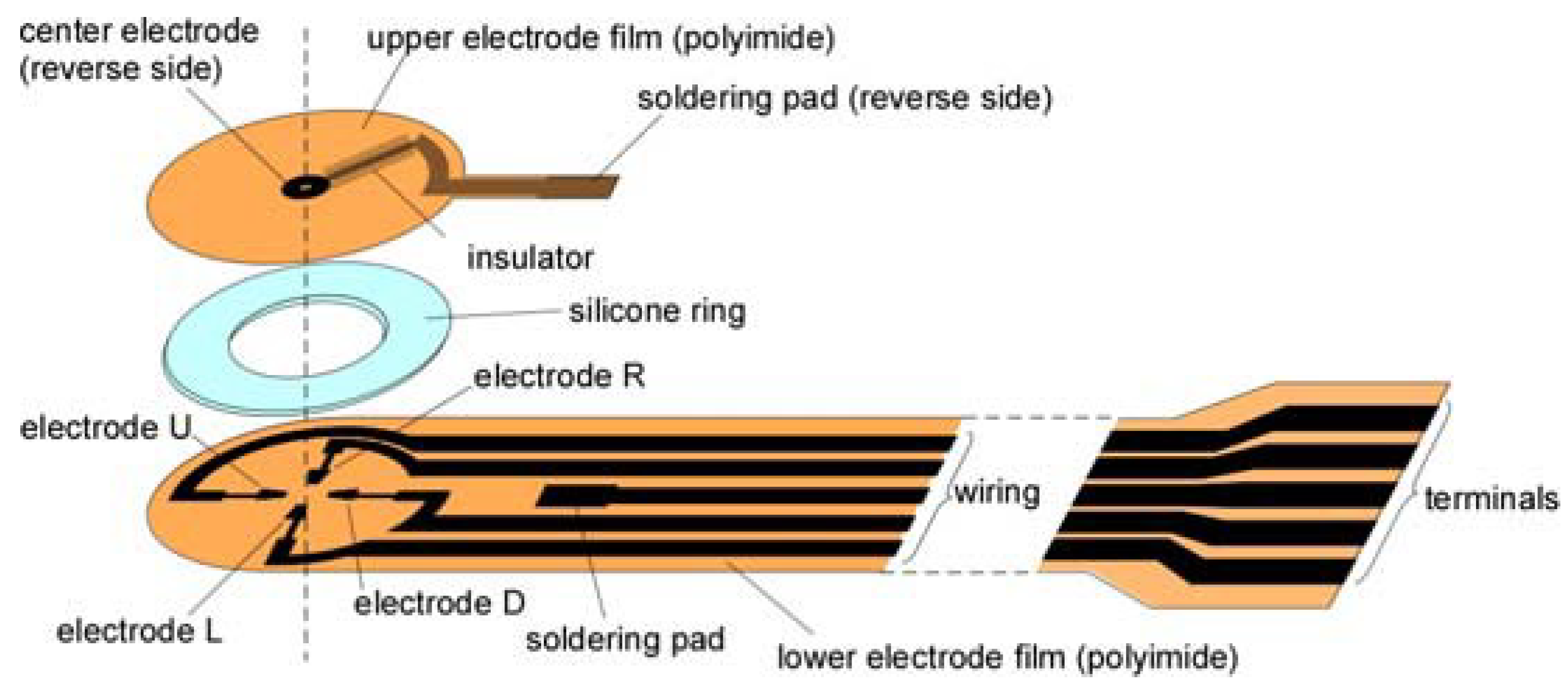
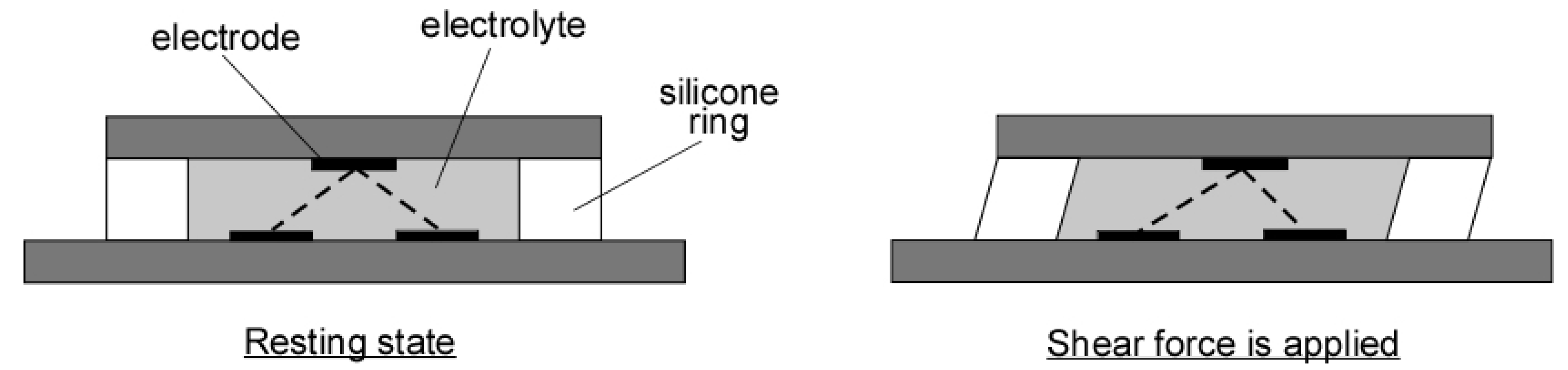
2. Materials and Methods

The sensor was prepared by the method written in our previous paper [6]. We prepared all the parts in our laboratory. The electrode films were prepared using a specially developed method that uses a laser printer and an electron beam evaporator [7]. Since our electrode film is capable of soldering, the electrode patterns of upper and lower films were connected by a spot soldering. The silicone rubber ring was manufactured from a plain rubber sheet (thickness: 0.5 mm) using a cutting plotter. The lamination of the parts was done via an adhesive using our own equipment which enables accurate alignment.
The measurement system consists of a portable measuring circuit and a notebook computer. The configuration and functions of a single sensor system are described in the reference [6], and we explored it as a multi-sensor measurement system. The main part of the circuit was a tiny microcomputer board. A sinusoidal wave (5 kHz, −200 to +200 mV) was applied on each electrode and the corresponding current was amplified, half-wave rectified, smoothed, and finally measured through an analog-to-digital converter of the microcomputer. In the multi sensor system, the signals from the four sensors are sequentially switched by the analog multiplexer.
Response evaluation of the sensor was performed by a self-made evaluation apparatus [6]. This apparatus includes a fixed plate and a movable plate, and a wire cable is connected to the movable plate via a pulley. A sensor is sandwiched between a fixed plate and a movable plate, and a shearing force can be applied by placing a weight on a dish located ahead of the cable.

3. Results and Discussion

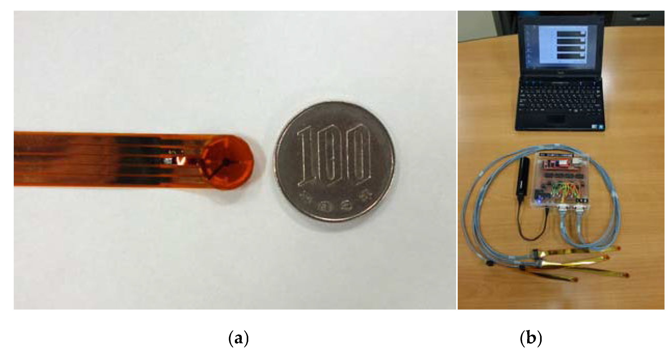
3.1. Sensor and Its Performance

The overview of the sensor and the entire system are shown in Figure 3. The diameter of the sensor head was 10 mm and the thickness was about 0.7 mm (Figure 3a). The entire system as shown in Figure 3b is composed of a mobile circuit and a notebook computer. The typical sensor response is shown in Figure 4. The sensor simultaneously measures the X component and the Y component of the shear load. In this plot, the shear load of 1.96 N and 4.90 N were repetitively added and the sensor response is demonstrated reproducible.

3.2. Application Example

A simple application test was performed using the multi-sensor measuring system and a wheel chair (Figure 5). Two sensors were attached to the buttocks of the pants with double-sided tape (Figure 5a). The mobile measurement circuit was put in the pocket on the back of the wheel chair. After that, we asked the subject to sit in the wheel chair and got various static poses at regular intervals during the measurement. A measurement example is shown in Figure 5b. It can be seen that there are cases where the measurement results are the same direction in the left and right sensors and in the opposite direction. In addition, even if the same tendency is seen, it can be seen that the size differs considerably between the left and right. Also, it can be seen that there is a case that a large force is sustained continuously while keeping the same posture. This sustained continuation of force suggests the possibility of leading to pressure ulcers after inhibiting blood flow and shows the importance of accumulation of careful experiments for simultaneous measurement of shear forces at several places in the future.

4. Conclusions

Our sensor produces reproducible shear force measurements. This time, with the development of the multi-sensor system, simultaneous measurement of the shear force at multiple parts of the body became possible. Using this, we successfully obtained experimental data by attaching two sensors to a human body, suggesting a possibility of various future applications.

Acknowledgments

This work was supported by JSPS KAKENHI Grant Numbers JPC15K01496 and JP18K11419.

Conflicts of Interest

The authors declare no conflict of interest.

References

  1. Sanders, J.E.; Daly, C.H. Normal and shear stresses on a residual limb in a prosthetic socket during ambulation: Comparison of finite element results with experimental measurements. J. Rehabil. Res. Dev. 1993, 30, 191–204. [Google Scholar] [PubMed]
  2. Dinsdale, S. Decubitus ulcers: Role of pressure and friction in causation. Arch. Phys. Med. Rehabil. 1974, 55, 147. [Google Scholar] [PubMed]
  3. Bennett, L.; Kavner, D.; Lee, B.; Trainor, F. Shear vs. pressure as causative factors in skin blood flow occlusion. Arch. Phys. Med. Rehabil. 1979, 60, 309–314. [Google Scholar] [PubMed]
  4. Reichel, S.M. Shearing force as a factor in decubitus ulcers in paraplegics. J. Am. Med. Assoc. 1958, 166, 762–763. [Google Scholar] [CrossRef] [PubMed]
  5. Toyama, S.; Utsumi, S.; Nakamura, T.; Noguchi, T.; Yoshida, Y. A novel thin shear-stress sensor using electrolyte as a conductive element. Sens. Lett. 2013, 11, 442–445. [Google Scholar] [CrossRef]
  6. Toyama, S.; Tanaka, Y.; Shirogane, S.; Nakamura, T.; Umino, T.; Uehara, R.; Okamoto, T.; Igarashi, H. Development of wearable sheet-type shear force sensor and measurement system that is insusceptible to temperature and pressure. Sensors 2017, 17, 1752. [Google Scholar] [CrossRef]
  7. Toyama, S.; Tanaka, Y.; Ishikawa, Y.; Hara, K. Simple fabrication method to produce flexible electrode capable of soldering. Sens. Mater. 2013, 28, 279–288. [Google Scholar] [CrossRef]
Figure 1. The sensor is composed of two electrode films, a silicone rubber ring, and an electrolyte (liquid). An electrode (central electrode) is fabricated on the upper side film and four electrodes are symmetrically arranged on the lower film.
Proceedings 02 00704 g001
Figure 2. Representative scheme illustrating the working principle of the shear force sensor.
Proceedings 02 00704 g002
Figure 3. Photographs of developed (a) sensor and (b) multi-sensor measurement system.
Proceedings 02 00704 g003
Figure 4. Typical sensor responses upon the application of shear load: (a) Shear load was repeatedly applied towards the -X direction; (b) Shear load was repeatedly applied towards the -Y direction.
Proceedings 02 00704 g004
Figure 5. Preliminary experiment; (a) photo showing how sensors were installed; (b) output data of each sensor.
Proceedings 02 00704 g005
Publisher’s Note: MDPI stays neutral with regard to jurisdictional claims in published maps and institutional affiliations.

