Abstract
For the considered application of a Fourier Transform InfraRed (FTIR) spectrometer, a functional package and an inkjet-printed capacitive position sensor are built. The package is made of 3D-printed copper. The copper is then coated with insulator onto which inkjet-printed silver electrodes are subsequently applied. The whole structure builds up a capacitive position sensor. The target application is to measure the position of an electrostatically actuated Micro Electro Mechanical System (MEMS) mirror with nanometer accuracy at high bandwidths and large position offset. The MEMS mirror is part of a Michelson interferometer setup and driven at resonance. The large oscillation amplitude and high required resolution at resonance of the MEMS mirror are also the reason for high demands on the position measurement. Robustness against disturbing frequencies is assured by employment of a carrier-frequency read-out structure.
1. Introduction
Electrostatically driven MEMS mirrors, oscillating at their mechanical resonance, are ideally suited for the application in interferometers: they enable faster measurements with high spectral resolutions (compare [1,2] for a more detailed system description). The application in a Fourier Transform Infrared (FTIR) spectrometer (setup shown in Figure 1) still makes high demands on system performance: Fast position tracking of the MEMS mirror is necessary to keep the measurement time low and to provide a sufficient Signal to Noise Ratio (SNR). Reasonable position measurement accuracy has to be achieved to be able to add spectra congruently and to avoid smearing. Additionally, the high-voltage electrostatic actuation may introduce noise and act as a disturber. Existing devices rely on optical position measurement [3,4]. Such optical feedback represents a fast and accurate way to measure the position, but also increases the weight and size of the devices. Additionally, the optical setup presents tight requirements regarding the diode mounting and poses a variety of engineering challenges. A multilayer, inkjet-printed capacitive position sensor is consequently built to ease the production of miniaturized devices. To provide electrical and mechanical shielding in a customizable housing, 3D-printed copper is used as substrate. 3D-printing is subject to intense research efforts and in the meanwhile offers high accuracy at moderate costs. Thus, 3D-printing is often employed to realize low-volume products which require individual adaptations, especially also for sensory prototypes [5]. Through the variety of materials offered, the fabricated devices can also withstand harsh environmental conditions. Inkjet-printing provides great potential for electronics manufacturing and for sensors in particular [6,7].

Figure 1.
Spectrometer and sensor system overview.
2. System Description
2.1. Spectrometer
A well-studied setup to construct an FTIR spectrometer device is the Michelson interferometer setup. This setup, as illustrated in Figure 1, is composed of an InfraRed (IR) source and two mirrors suspended in an angle of ϕ = 90°. One of the mirrors is moveable. Distinct wavelengths of the IR light are selected which depend on the moving mirror’s position. One movement of the mirror, which covers the full possible pathlength, the mirror can traverse, is called a scan. Important measures are: a high number of scans N to increase the signal-to-noise ratio as SNR N1/2, the congruency of added spectra (adding spectra non-congruently results in a smeared result-spectrum) and prevention of noise as this blurs peaks and could then lead to miss-identification of substances. Consequently, a concise knowledge of the mirror position during each scan is crucial.
2.2. Sensor Front-End
A 3D-printed copper body is used as substrate for a capacitive inkjet-printed sensor. The inkjet-printed silver electrode is printed as multilayer structure [8] with a diameter of de = 5 mm, layer thicknesses and process details can be found in [8]. Two layers, an insulating and a conductive layer have to be printed and cured subsequently. The 3D-printed copper body provides a functional housing because the copper is conductive and can thus be used for shielding as is necessary below the capacitive sensing electrode.
2.3. Analog Readout Hardware
An analog circuitry attached as daughterboard to an FPGA system (see [1,2]), provides ultra-low noise amplification and conditioning of the input signal. A carrier frequency system is used as input circuitry structure and enables separation of the measurement- from other system frequencies, and flexible choice of bandwidth. Here, the measurement capacitance is one component of a voltage divider. The second component is a shunt resistor of Rs = 50 Ω to provide a power-matched system for common communications equipment. In a carrier frequency system, the signal of interest is modulated onto a carrier at the sensor front-end. At the read-out, the input is demodulated to retrieve the measured quantity.
3. Measurement Results
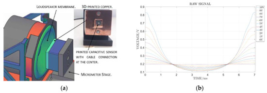
To evaluate the nanometer resolution capabilities of the developed system, a demonstrator was built (Figure 2a). To avoid the necessity of a high quality vacuum, this demonstrator consists of a loudspeaker membrane to which the sensor system is opposed. The sensor is mounted on a μm-stage, so that the position of the micromirror relative to the membrane is measurable in the μm range. In the demonstrator setup, position resolutions of respos = 100 nm at a sensor distance of ds = 0.4 mm could be shown for the dynamic system at a membrane excitation frequency of fexc = 140 Hz. Resolutions down to respos = 20 nm could be demonstrated using the appropriate signal processing [9]. In Figure 2b the measurement results for the membrane approaching the sensor and departing from the sensor are illustrated. These results illustrate also the nonlinearity of the underlying capacitive measurement principle: the position resolution of the path, where the membrane approaches the sensor, is significantly higher than the resolution of the path, where the membrane departs from the sensor.

Figure 2.
Illustration of the demonstrator setup and measurement results. (a) Demonstrator-setup developed to show the resolution capabilities of the printed system. (b) Measurement results with the demonstrator and the printed capacitive sensor mounted in a distance of dsens = 1 mm.
4. Robustness Analysis
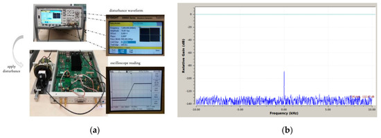
In the considered application for position sensing of the MEMS mirror, a known source of disturbance is the large mirror excitation signal. The developed carrier frequency sensing concept is designed to be unaffected by the mirror excitation. In order to demonstrate this, a PWM, i.e., rectangular, signal of faist = 1 kHz and an amplitude of = 20 V peak-peak is connected to the sensor’s counter electrode (see Figure 3a). Then, the FFT of the received signal is observed. In the resulting FFT, there is no other signal peak than the carrier (Figure 3b): obviously, it can be expected that there is no disturbing influence from the mirror excitation signal. Furthermore, in the true system configuration, the excitation signal is not directly at the sensor’s counter electrode, but at the mirror rim. However, restrictions have to be made for the edge steepness of the PWM signal have to be made. Signals with higher change-rates than rc = 25 V/μs cause saturation of the analog amplifier chain.

Figure 3.
Illustration of the robustness analysis setup and results. (a) Demonstrator-setup to evaluate the robustness against disturbers. (b) Measurement results with a disturbance signal applied to the counter electrode of the mirror position sensor.
5. Conclusions
In this work, we presented robust capacitive position measurement system based on a 3D- and inkjet-printed capacitive sensor system in combination with a carrier frequency system for the read-out. This system is able to achieve nanometer position resolutions at high bandwidths and high position offset in combination with a limited sensor diameter. We can thus show that a successful combination of the read-out strategy and rapid-prototyping technologies enables high resolution sensing at reduced system sizes.
Funding
This work has been supported by the COMET K1 ASSIC Austrian Smart Systems Integration Research, Center. The COMET-Competence Centers for Excellent Technologies-Program is supported by BMVIT, BMWFW and the federal provinces of Carinthia and Styria.
Conflicts of Interest
The authors declare no conflict of interest.
References
- Faller, L.M.; Leitzke, J.P.; Zangl, H. Design of a Fast, High-Resolution Sensor Evaluation Platform applied to a Capacitive Position Sensor for a Micromirror. In Proceedings of the 2017 IEEE International Instrumentation and Measurement Technology Conference (I2MTC), Turin, Italy, 22–25 May 2017. [Google Scholar]
- Faller, L.M.; Mitterer, T.; Leitzke, J.P.; Zangl, H. Design and Evaluation of a Fast, High-Resolution Sensor Evaluation Platform applied to MEMS Position Sensing. IEEE Trans. Instrum. Meas. 2017, 67, 1014–1027. [Google Scholar] [CrossRef]
- Tortschanoff, A.; Lenzhofer, M.; Frank, A.; Kenda, A.; Sandner, T.; Schenk, H. Improved MEMS based FT-IR Spectrometer: Position Encoding and Oosed Loop Control. In Proceedings of the IEEE International Symposium on Optomechatronic Technologies, Istanbul, Turkey, 21–23 September 2009. [Google Scholar]
- Lenzhofer, M.; Tortschanoff, A.; Fank, A.; Sandner, T.; Schenk, H.; Kraft, M.; Kenda, A. MOEMS translator actuator characterisation, position encoding and closed-loop control. Microsyst. Technol. 2010, 16, 901–907. [Google Scholar] [CrossRef]
- Zega, V.; Credi, C.; Bernasconi, R.; Langfelder, G.; Magagnin, L.; Levi, M.; Corigliano, A. The First 3-D-Printed z-Axis Accelerometers With Differential Capacitive Sensing. IEEE Sens. J. 2018, 18, 53–60. [Google Scholar] [CrossRef]
- Blaz, N.; Kisic, M.; Zivanov, L.; Damnianovic, M. Displacement Sensor Fabricated by 3D Additive Manufacturing. In Proceedings of the IEEE 40th International Spring Seminar on Electronics Technology, Sofia, Bulgaria, 10–14 May 2017. [Google Scholar]
- Krivec, M.; Lenzhofer, M.; Moldaschl, T.; Pribosek, J.; Abram, A.; Ortner, M. Inkjet Printing of Multi-Layered, Via-Free Conductive Coils for Inductive Sensing Application. Microsyst. Technol. 2018, 24, 2673–2682. [Google Scholar] [CrossRef]
- Faller, L.M.; Krivec, M.; Abram, A.; Zangl, H. AM Metal Substrates for Inkjet-Printing of Smart Devices. Meter. Charact. 2018, 143, 211–220. [Google Scholar] [CrossRef]
- Faller, L.M.; Zangl, H. Feasibility Considerations on an Ilnkjet-Printed Capacitive Postion Sensor for Electrostatically Actuated Resonant MEMS-Mirror Systems. IEEE J. Microelectromech. Syst. 2017, 26, 559–568. [Google Scholar] [CrossRef]
Publisher’s Note: MDPI stays neutral with regard to jurisdictional claims in published maps and institutional affiliations. |
© 2018 by the authors. Licensee MDPI, Basel, Switzerland. This article is an open access article distributed under the terms and conditions of the Creative Commons Attribution (CC BY) license (https://creativecommons.org/licenses/by/4.0/).