Proceeding Paper

Buck Converter for Low-Power PV Modules: A Comparative Study †

Department of Electronic Engineering, Universitat Politècnica de Catalunya—BarcelonaTech, 08860 Castelldefels (Barcelona), Spain
*
Author to whom correspondence should be addressed.
Presented at the Eurosensors 2018 Conference, Graz, Austria, 9–12 September 2018.
Proceedings 2018, 2(13), 1050; https://doi.org/10.3390/proceedings2131050
Published: 26 November 2018
(This article belongs to the Proceedings of EUROSENSORS 2018)

Abstract

:
Autonomous sensors that harvest energy from the environment usually employ a dc/dc converter to regulate the operating voltage of the energy transducer around its maximum power point (MPP). In this context, this work evaluates the efficiency of a buck converter when regulating the operating point of two low-power photovoltaic (PV) modules subjected to different irradiance levels. The buck converter operates in burst mode (BM) and is able to transfer the energy from the PV module to a storage unit through an optimal value of the inductor current. Experimental results show that an irradiance increase can cause either an increase or a decrease of the converter efficiency. This is because the higher the irradiance, the higher both the MPP voltage and current of the PV module, which involve opposite effects in terms of the converter efficiency.

1. Introduction

Solar-powered sensor nodes usually employ a dc/dc converter between the PV module and a storage unit (e.g., a rechargeable battery) to maintain the operating voltage of the module around its MPP and to efficiently transfer the energy [1,2], as shown in Figure 1a. Therefore, the converter is applied herein to regulate its input voltage, rather than its output voltage as occurs when the converter regulates the supply voltage of the sensor electronics [3]. In this scenario, converters operating in a conventional pulse-width modulation (PWM) technique are not recommended, especially for subwatt PV modules, because it involves a fixed switching frequency that generates significant switching losses and, hence, a low efficiency. In order to reduce such losses in PWM converters, several methods have been reported: dynamic adjustment of the gate-driving voltage of the power transistors, dynamic adjustment of the active size of the power transistors, soft-switching techniques [4], and charge-recycling techniques [5].
The efficiency of the dc/dc converter can also be improved by operating in a variable-frequency mode such as pulse-frequency modulation (PFM) [6] or BM [7,8]. In PFM, the switching frequency is scaled down with the PV current, whereas in BM, the converter operates in PWM sporadically, thus resulting in a burst of energy pulses transferred to the output, as shown in Figure 1b. Moreover, in BM, there is an optimal inductor current (IL0,opt) to transfer the energy during the burst, which was studied for a boost [7] and a buck [8] converter when regulating the operating voltage of a low-power PV module. Using [8] as a reference, this work aims to evaluate the efficiency of a burst-mode buck dc/dc converter when regulating the operating point of two low-power PV modules of different technology (monocrystalline and amorphous).

2. Materials and Methods

Table 1 summarizes the features of the two commercial low-power PV modules under test (from now on: PV-1 and PV-2), which provide a power of tens of mW suitable to supply microcontroller-based sensor nodes [9,10,11]. These modules were subjected, through a LED array, to three irradiance levels identified as I33, I66, and I100 that correspond to 330, 660, and 1000 W/m2, respectively, in terms of power generated at the MPP. At each irradiance level, the current generated by the module was measured at different voltages using a source-measurement unit (Agilent B2901) so as to determine the MPP voltage. The modules were kept at approximately room temperature by injecting fresh air on them through a fan.
The operating point of the PV modules was then regulated around the MPP voltage by a commercial buck dc/dc converter (TPS62750 from Texas Instruments) operating in BM. This converter was selected since it enables us to adjust the average input current and, hence, indirectly the average inductor current (IL0 in Figure 1b) using an external resistor. The BM operation was ensured by controlling the converter feedback input through a hysteresis comparator (LTC1440 from Linear Technology) [8]. Other remarks about the measurement setup are the following:
  • The operating voltage (Vin in Figure 1a) was provided by a dc voltage source, instead of an MPP tracking circuit, based on the experimental results of the PV characterization.
  • The actual value of IL0 was monitored by a clamp-on current probe (CP030A) connected to a digital oscilloscope (Lecroy Wave Surfer 3024).
  • A dc voltage source (with a resistor in parallel [12]) emulated a rechargeable battery. The output voltage (Vout in Figure 1a) was set to 3 V for PV-1, and 2.4 V for PV-2, thus emulating different states of charge of two cylindrical NiMH secondary batteries in series. Electrical limitations of the converter forced us to use different values of Vout for each module.
  • The input power was calculated as Pin = VinIin (see Figure 1a), whereas the average output power (Pout) was measured by a power analyzer (Yokogawa WT310). The efficiency of the converter was estimated as η = Pout/Pin.

3. Experimental Results

The power-voltage curves of the PV modules under test are shown in Figure 2 for the three irradiance levels. For both PV modules, the power, current (IMPP), and voltage (VMPP) at the MPP increased with increasing the irradiance level, although the increment of the MPP voltage (from I66 to I100) was more significant in PV-2. In comparison with the typical values reported in Table 1, a higher voltage and a lower current were observed in PV-1, but the opposite in PV-2. Such differences are around 10% or smaller and can be ascribed to manufacturing tolerances and thermal effects.
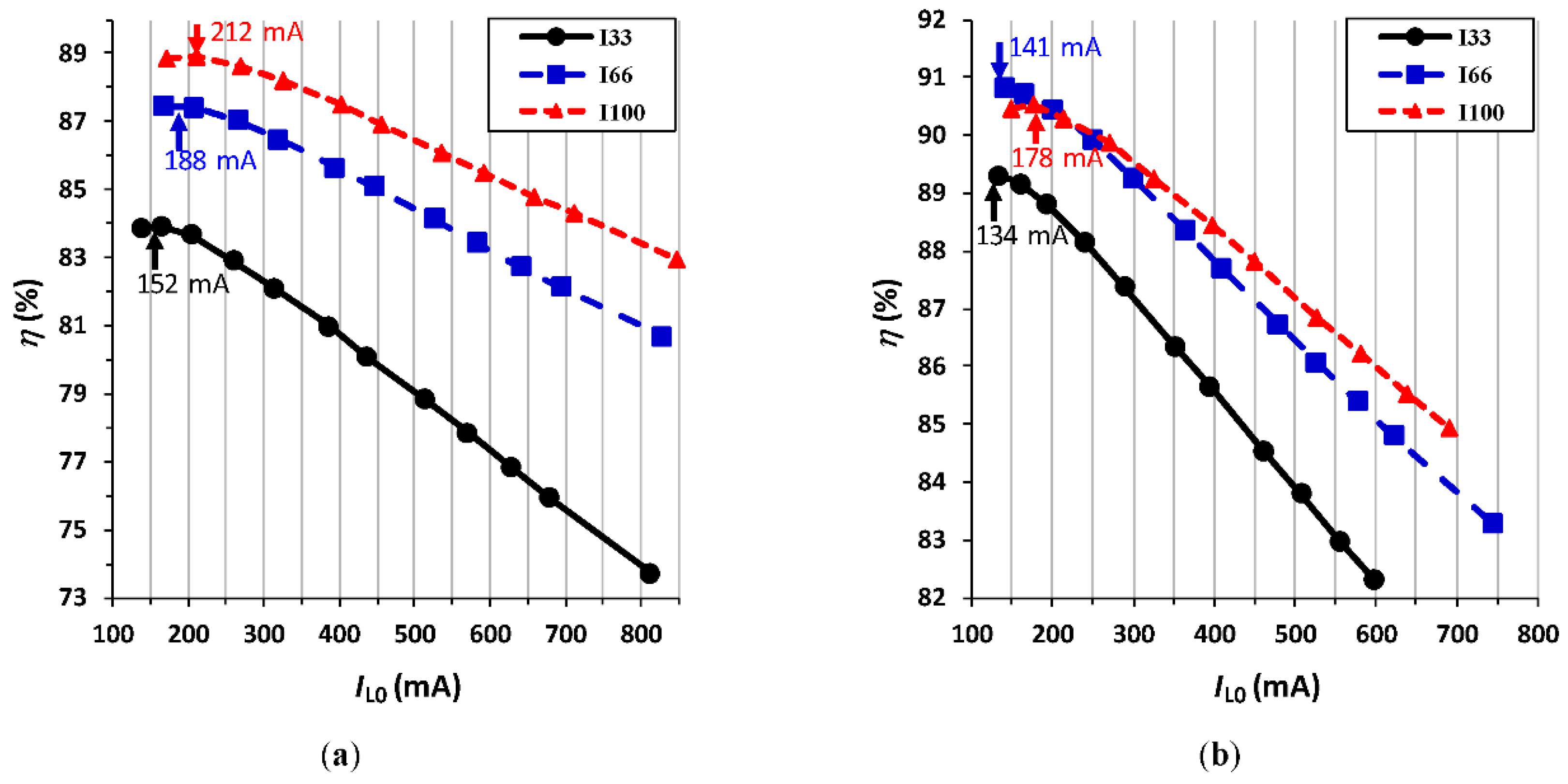
Figure 3 represents η versus IL0 when regulating the operating point of the PV modules around the MPP voltages shown in Figure 2. For both modules, IL0,opt increased with increasing the irradiance, which agrees with [8] considering that both VMPP and IMPP (or Vin and Iin from the converter’s point of view) increased with increasing the irradiance. However, an irradiance increase did not involve unavoidably an increase of the converter efficiency, as does happen in a boost converter [7]. This is because VMPP and IMPP cause opposite effects on the converter efficiency [8]: η increases (decreases) with increasing IMPP (VMPP). Therefore, depending on which effect dominates, η will either increase or decrease. For instance, in Figure 2b, VMPP had a significant increase from I66 to I100 that caused an efficiency decrease. This decrease was such that the resulting efficiency at I100 became lower than that at I66 for low values of IL0, as shown in Figure 3b.

4. Conclusions

This work has evaluated the efficiency of a buck dc/dc converter operating in BM when regulating the operating point of two low-power PV modules of different technology. For both modules, it has been experimentally reported that the optimal inductor current related to the BM increases with increasing the irradiance level. However, the efficiency of the buck converter can either increase or decrease with increasing the irradiance. This is because the higher values of MPP voltage and current usually associated to a higher irradiance cause opposite effects on the converter efficiency. Therefore, depending on which effect dominates, the converter shows either an increase or a decrease of its efficiency. This performance is clearly different to that found in boost dc/dc converters, where the efficiency always increases with increasing the irradiance.

Acknowledgments

This work was supported by the Spanish Ministry of Economy and Competitiveness and the European Regional Development Fund under project TEC2016-76991-P.

Conflicts of Interest

The authors declare no conflict of interest. The founding sponsors had no role in the design of the study; in the collection, analyses, or interpretation of data; in the writing of the manuscript, and in the decision to publish the results.

References

  1. Ruan, T.; Chew, Z.J.; Zhu, M. Energy-aware approaches for energy harvesting powered wireless sensor nodes. IEEE Sens. J. 2017, 17, 2165–2173. [Google Scholar] [CrossRef]
  2. Rawy, K.; Kalathiparambil, F.; Maurath, D.; Kim, T.T. A self-adaptive time-based MPPT with 96.2% tracking efficiency and a wide tracking range of 10 µA to 1 mA for IoT applications. IEEE Trans. Circuits Syst. I Reg. Pap. 2017, 64, 2334–2345. [Google Scholar] [CrossRef]
  3. Reverter, F.; Gasulla, M. Optimal inductor current in boost dc/dc converters operating in burst mode under light-load conditions. IEEE Trans. Power Electron. 2016, 31, 15–20. [Google Scholar] [CrossRef]
  4. Wang, J.M.; Wu, S.T. A synchronous buck dc–dc converter using a novel dual-mode control scheme to improve efficiency. IEEE Trans. Power Electron. 2017, 32, 6983–6993. [Google Scholar] [CrossRef]
  5. Ha, J.W.; Park, B.H.; Chun, J.H. A 7-MHz integrated peak-current-mode buck regulator with a charge-recycling technique. IEEE Trans. Circuits Syst. II Exp. Briefs 2017, 64, 797–801. [Google Scholar] [CrossRef]
  6. Simjee, F.I.; Chou, P.H. Efficient charging of supercapacitors for extended lifetime of wireless sensor nodes. IEEE Trans. Power Electron. 2008, 23, 1526–1536. [Google Scholar] [CrossRef]
  7. Reverter, F.; Gasulla, M. Optimal inductor current in boost dc/dc converters regulating the input voltage applied to low-power photovoltaic modules. IEEE Trans. Power Electron. 2017, 32, 6188–6196. [Google Scholar] [CrossRef]
  8. Reverter, F.; Glaser, C.; Gasulla, M. Efficiency optimization in burst-mode buck dc/dc converters for sensor nodes. IEEE Sens. J. 2018, 18, 7141–7149. [Google Scholar] [CrossRef]
  9. Reverter, F. Power consumption in direct interface circuits. IEEE Trans. Instrum. Meas. 2013, 62, 503–509. [Google Scholar] [CrossRef]
  10. Sifuentes, E.; Gonzalez-Landaeta, R.; Cota-Ruiz, J.; Reverter, F. Measuring dynamic signals with direct sensor-to-microcontroller interfaces applied to a magnetoresistive sensor. Sensors 2017, 17, 1150. [Google Scholar] [CrossRef] [PubMed]
  11. Sifuentes, E.; Gonzalez-Landaeta, R.; Cota-Ruiz, J.; Reverter, F. Microcontroller-based seat occupancy detection and classification. In Proceedings of the Eurosensors XXXII, Graz, Austria, 9–12 September 2018. [Google Scholar]
  12. Reverter, F.; Gasulla, M. Improving the efficiency of PV low-power processing circuits by selecting an optimal inductor current of the DC/DC converter. In Proceedings of the Eurosensors XXVIII, Brescia, Italy, 7–10 September 2014; pp. 1214–1217. [Google Scholar]
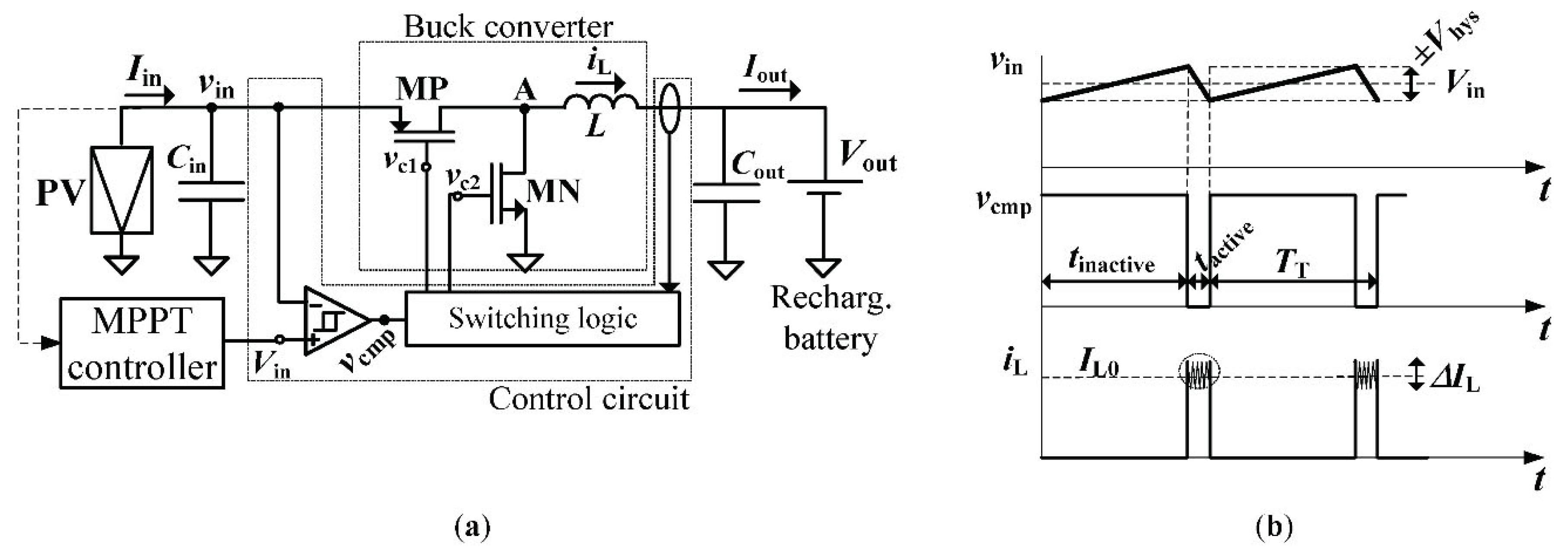
Figure 1. (a) Power processing circuit for a low-power PV module based on a synchronous buck dc/dc converter; (b) resulting waveforms when the converter operates in BM.
Proceedings 02 01050 g001
Figure 2. Power-voltage curves of the commercial low-power PV modules: (a) PV-1; (b) PV-2.
Proceedings 02 01050 g002
Figure 3. Efficiency versus IL0 when regulating the operating voltage of (a) PV-1; (b) PV-2.
Proceedings 02 01050 g003
Table 1. Features of the commercial low-power PV modules.
FeaturePV-1PV-2
ManufacturerIxysPower Film
ModelXOB17-04x3SP4.2-37
TechnologyMonocrystallineAmorphous
Modules connected in series31
Typ. voltage/current/power (1)4.59 V/11.7 mA/53.7 mW (2)4.2 V/22 mA/92.4 mW
(1) At MPP and standard test conditions (1000 W/m2 with AM1.5 at 25 °C). (2) Assuming the three modules in series.
Publisher’s Note: MDPI stays neutral with regard to jurisdictional claims in published maps and institutional affiliations.