1. Introduction
Changing climate will have considerable impact on urban areas. One of the effects of this process on urban areas in Northern Europe is the increase of stormwater peak intensities during rain events [
1]. Current urban drainage systems (UDS) in these areas are not designed to cope with such extreme flowrates. Intense rainfall will cause the urban drainage system to become surcharged, which will consequently trigger pluvial floods. Rapid urbanization that is increasing the share of impermeable surfaces will accelerate the problem even more. As a result of these trends urban areas are considered highly vulnerable to climate change [
2].
There are several options available to alleviate the vulnerability and increase the resilience. According to Fletcher et al. [
3] these can be broadly divided into structural and non-structural measures, both of which are underpinned with mitigation of changes in flow regime and improvement of water quality. Low impact development (LID) is considered by many authors as one of the efficient structural methods, while best management practices (BMP) contribute to the non-structural category [
4,
5].
LID can also be characterized as a small scale stormwater treatment facility located near the source [
3]. LID techniques can be divided into two groups: (i) green solutions, e.g., bioretention systems and (ii) grey solutions, e.g., detention and retention tanks. Green solutions, also referred to as sustainable urban design systems (SUDS), attempt to restore natural hydrologic budget [
4] while detention tanks aim to accumulate the peak flow and discharge this into the system with a certain time lag [
6].
Storage facilities are added to the network to increase the capacity of the system and therefore reduce the risk of flooding in case of intense rainfall events. This extra volume can be achieved by adding off-line or in-line storage into the system. Typical off-line facilities are the detention tanks, having a connection to the stormwater pipeline. Free capacity of the drainage collectors has been often considered as in-line storage. Although effectiveness and optimal distribution of the off-line facilities is the objective of many recent studies [
7,
8,
9], in-line facilities are mainly considered as a possibility of utilizing the excess capacity of the pipeline, not specially designed for a storage [
10].
Real time control (RTC) methodology that emerged with the development of information and communication technology (ICT) aims to bridge the structural and the non-structural measures into one comprehensive solution. This is achieved by installing active network elements, e.g., weirs and valves into the UDS. These actuators will be automatically adjusted on the basis of the data from the network sensors and thus allow UDS to be adapted to the different loading conditions. Therefore, RTC is seen as a key technology to improve the operation of UDS [
11].
In this paper, the advantages of traditional off-line reservoirs are merged with a drainage pipeline to create a smart in-line storage concept in order to reduce effectively the peak flow rates.
2. Methodology
The main objective of this work is to find the most feasible solution to reduce stormwater peak runoff volume from compact new city development areas within existing urban space. Such redevelopment is typical for urban areas e.g., turning obsolete industrial zones into new living and business districts. As situated in the middle of urban area, constraints have to be imposed for the stormwater runoff into the existing UDS. In many cases due to limited free space available, it is not possible to choose SUDS for the peak flow reduction, since these require notably more land than grey solutions. Free space is usually scarce in these areas because of other underground communications, e.g., water supply, gas and electricity lines with their protection zones and additionally on the other hand, developers attempt to gain profit by maximizing the building footprints.
For that reason, present study focuses on underground solutions, requiring minimum construction area and thus suitable for dense urban environments. Distributed underground storages are considered feasible option to meet the criteria above [
12]. For the analysis, three different types of technical solutions were compared: (i) distributed off-line detention tanks; (ii) in-line storage facilities with no RTC and (iii) a new concept of in-line storage facilities coupled with RTC. All three options where evaluated in reference to the scenario with no LID measures used.
2.1. Technical Considerations
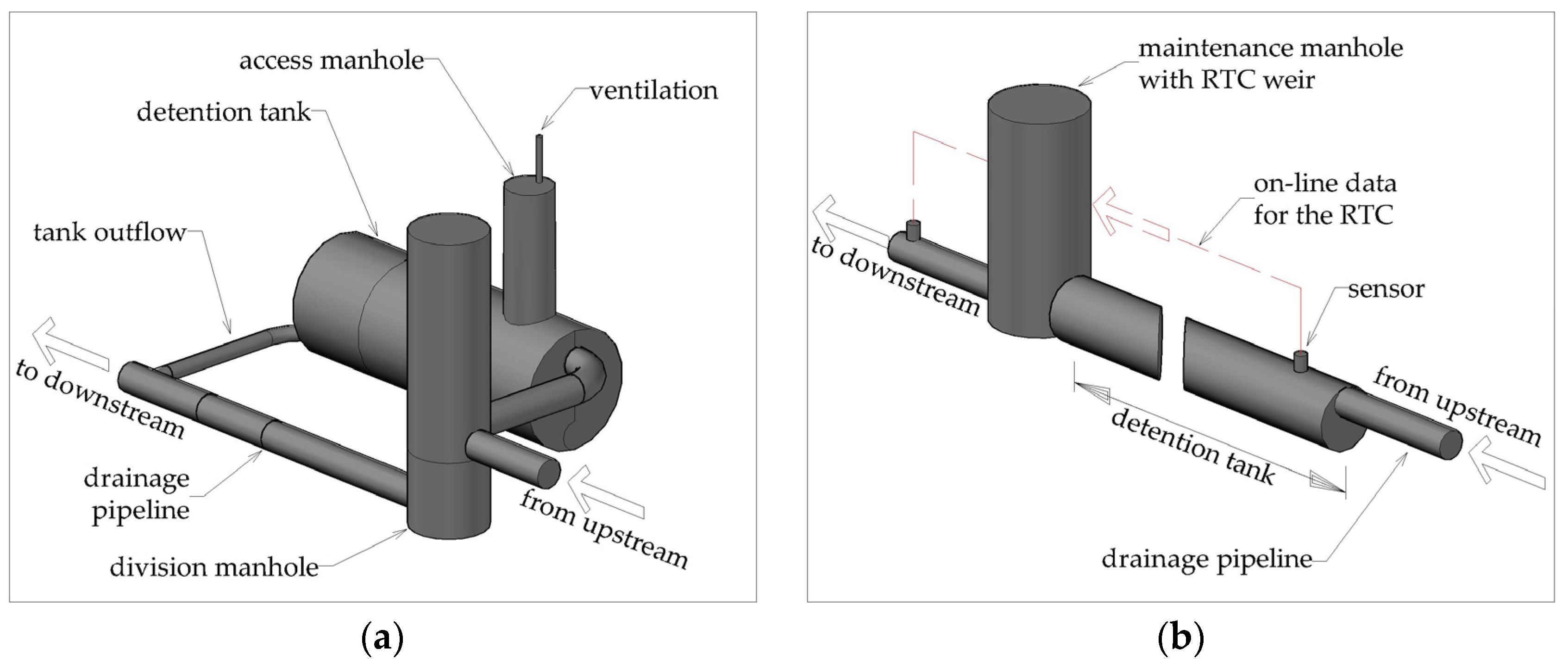
Distributed off-line detention tanks are usually cylinder shaped plastic barrels installed to the network with a connection to the pipeline. These will accumulate the excess water and will empty after the hydraulic grade line (HGL) in the system has lowered below a certain level (
Figure 1). For optimization process, it was assumed that the volume of the tanks will be combined from 50 m
3 cylinders, as these have still quite manageable dimensions for transportation and installation. It would be technically challenging to install larger barrels below street area because of the limited width of the street. It was also assumed that tanks will be filled and emptied by gravity flow. The barrels have usually one or two additional entrances for maintenance purpose.
In-line storage facilities are enlarged pipe sections installed into the network. During a rainfall event these pipe sections will be filled with water, hence reducing the peak flow at the outlet. Water flow to the downstream pipeline is usually restricted by orifice i.e., short pipe section with reduced diameter. Differently from off-line storage elements, water is always flowing through the facility. For the study it was assumed that the maximum diameter of these enlarged sections should not exceed 1m, as larger conduits would hinder installation of other communications in the street area.
Smart in-line storage facilities are a novel approach in stormwater management, which will combine traditional in-line storage described above with RTC system to make the unit adaptable to certain climate conditions. For that, water flow from the tank section is regulated by adjustable weir that will change its setting according to the on-line information from the network sensors. These sensors can measure water level in the upstream and in the critical points in the downstream network. Data from rain radar or rain gauges can also be utilized making RTC system even more pro-active. The optimization constrains used in the study were similar to the ordinary in-line storage facilities described above. In addition, it was assumed that maximum two weirs can be used for 10 ha catchment area.
2.2. Economic Aspects
Two cost components were used to find the feasible solution (
Table 1). First component, named as an investment cost (IC), comprised the infrastructure cost (pipes, manholes, equipment etc.) and cost of the construction works.
The second component, named as “penalty”, was imposed for the case when the technical solution did not fully meet the design constraints and therefore some extra investments were needed outside the street area, e.g., adding additional retention tanks on the plots. Penalty for the base scenario, i.e., with no LID used, took into account the replacement of the pipeline outside the development area in order to allow higher volumes to pass.
2.3. Optimization
Simple optimization was carried out to find the optimum dimensions and locations of the detention facilities. Standard rainfall intensity (28 mm/h) and duration (20 min) was applied for the study on the basis of Estonian Design Standard UDS [
13]. As the catchment area is estimated to be quite compact (10 ha) unified rain gauge was used for the whole area.
The following optimization constraints were considered: (i) availability of the free space for the construction and technical applicability as described in
Section 2.1; (ii) minimum IC; (iii) highest resilience, i.e., distance between the ground level and HGL is <0.5 m in case of peak flow moment. Penalties described in
Table 1 were imposed if the solution eventually did not fully meet the runoff threshold. Optimization results were tested and evaluated with the EPA SWMM 5.1 software.
3. Results
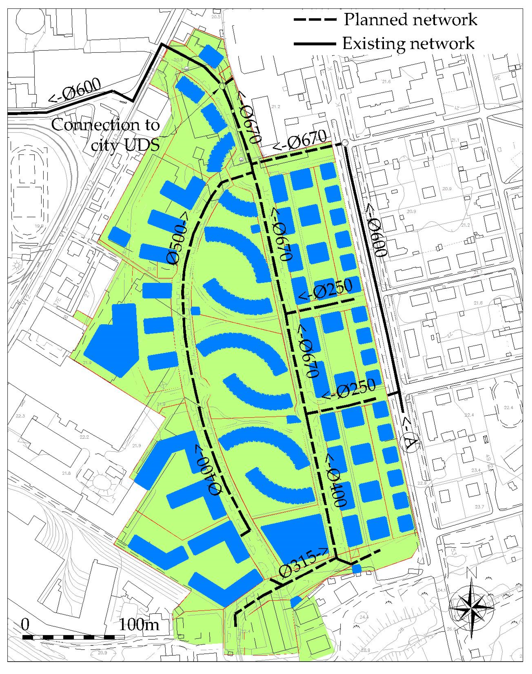
The efficiency analysis of the smart in-line storage facilities including the comparison with off-line and traditional in-line solutions has been carried out for 10 ha modern urban development area in Estonian capital Tallinn (
Figure 2). During the development the old obsolete factory territory will be turned into modern city environment with 1600 apartments and several offices. All the parking spaces for the vehicles will be constructed underground beneath the plots. The total area of the development is about 13 ha with the rate of impermeable surfaces >90%. The terrain has moderate (about 5%) slope from the south to the north. The infiltration and the evaporation in catchment areas was omitted to be in line with the cold climate conditions. Constant flow of 50 L/s representing the infiltration from the upstream catchment areas was applied to the point A (
Figure 2).
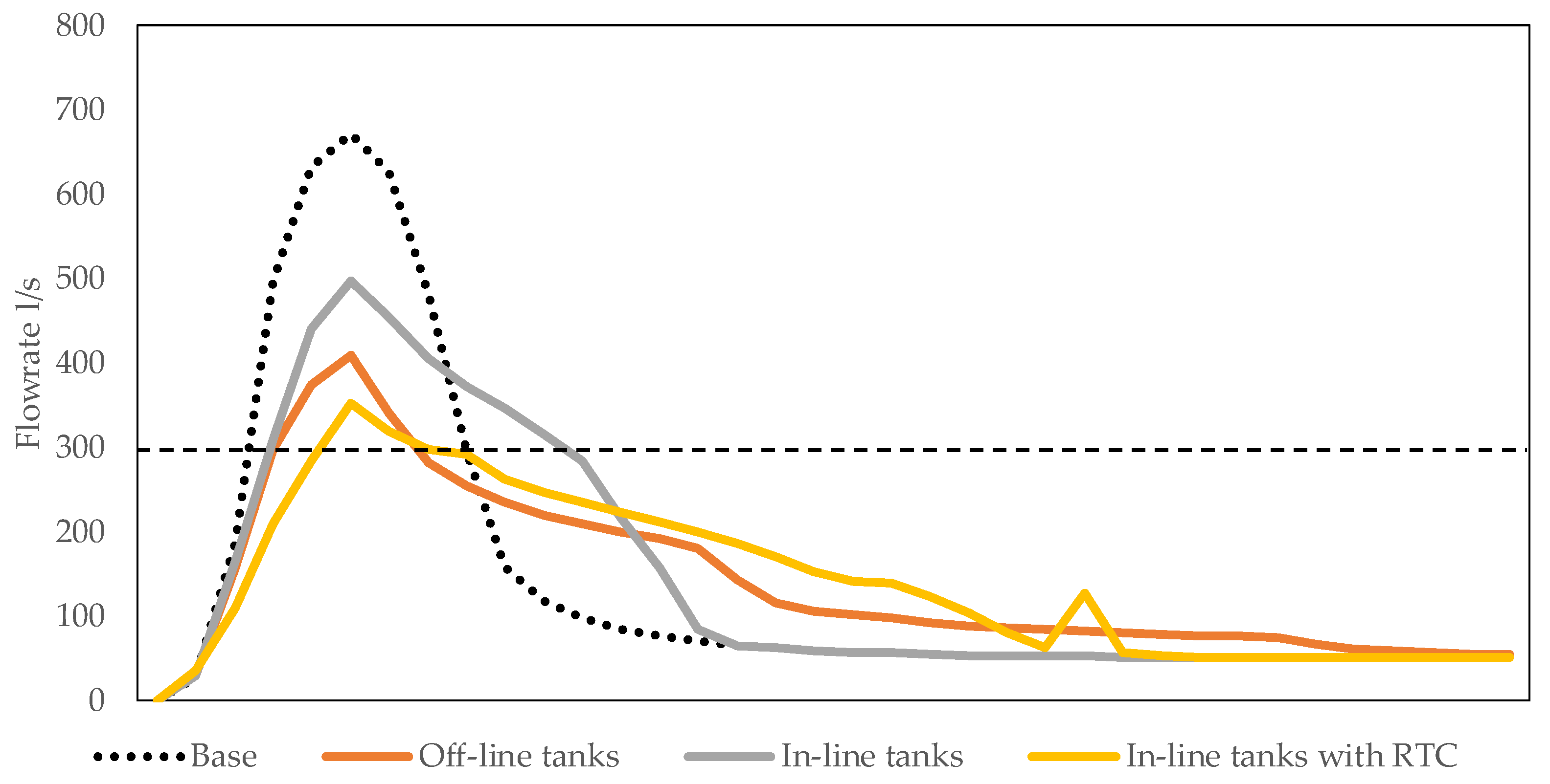
Due to the limited capacity of the existing downstream UDS, the local municipality has imposed the limit of 300 L/s for the peak runoff. Calculations showed that on the basis of the technical solution presented in the
Figure 2, i.e., no LID used, the peak runoff will be 670 L/s, which is more than two times higher than the allowance.
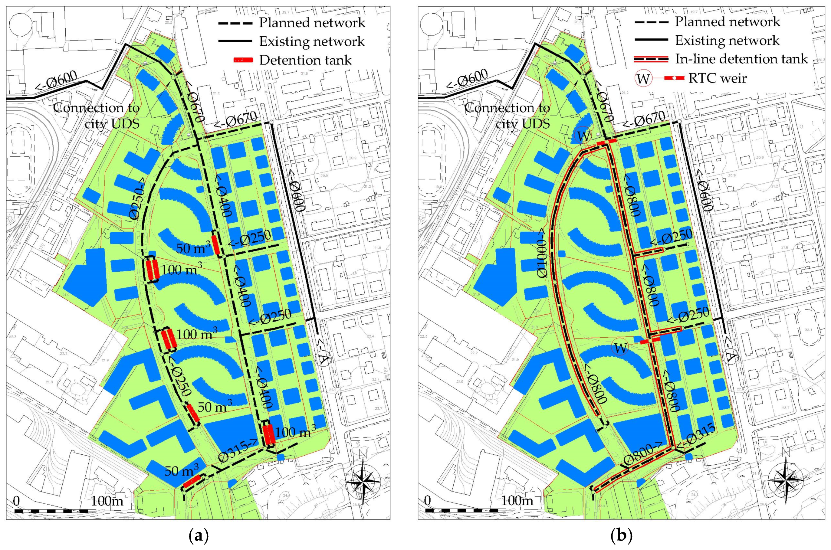
After the optimization process described in the
Section 2.3, totally six units of off-line storage tanks with a total volume of 450 m
3 were placed into the network on the locations shown in
Figure 3a. As the storage tanks will cut off some of the peak flowrate, it was possible to use smaller pipeline than in the case of no LID used (
Figure 2). In the case of the scenario with in-line storage option, the total length of accumulation pipeline designed was 0.9 km with the total volume of 480 m
3 (
Figure 3b). Conduit with reduced diameter of 300 mm was installed at the outflow to hinder the flow from the catchment area. For the fourth scenario, this diminished section was replaced with the RTC weir and one additional weir was installed to the middle of the main conduit section as presented in
Figure 3b. The operation of the weirs was controlled on the basis of water elevation in the preceding conduit section.
Results of the base scenario and three scenarios for the peak flow reduction are presented in the
Figure 4. It can be seen that none of the options fully meet the outflow constraint (300 L/s), therefore some LID facilities had to be chosen on the plots to provide the additional cut. From the hydraulic efficiency the scenario four—in-line detention with RTC—showed the highest results, reducing the peak flow up to 47%. It is important to note that in-line detention without RTC (option two) has on the contrary the lowest effect on the peak flow reduction (26%). Traditional off-line detention gained the result of 39%, which correlates with the numbers presented in other research articles [
7,
9].
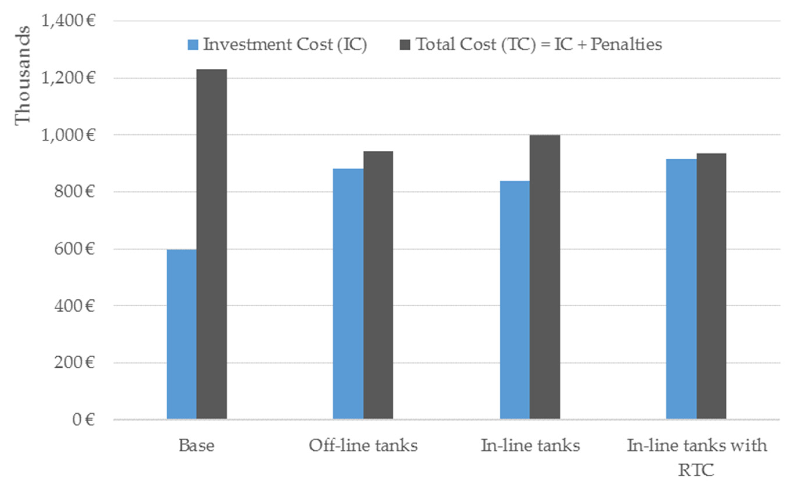
From the economic perspective it is quite obvious that the base scenario has the lowest IC as this solution has no costly facilities for the flow detention (
Figure 5). The IC of other three options is in average 47% higher, which may lead to the decision that any flow detention is unfeasible because of economic reasons. Therefore, penalty costs were calculated for the four scenarios on the basis of the methodology described in the
Section 2.2 to better understand the real cost of the solutions. As it can be seen from the
Figure 5, the base scenario has actually the highest total cost (TC), that is penalty cost added to IC. High penalty cost stems from the need to rebuild about 0.9 km of drainage collectors in the downstream to reduce the risk of network surcharge. For other three options, the penalty cost was calculated on the basis of additional LID facilities needed on the plots.
It can be seen from the results that in-line tanks with RTC and traditional off-line tanks have similar total costs. The TC of in-line tanks is the highest because of substantial investments are needed for retention tanks on the plots to cut the peak flow to the target level (300 L/s). As a result the TC of these three options are 24% lower than the base scenario.
4. Discussion
Although it might seem that traditional UDS are the most cost effective solution for new dense development areas conceived to the existing city space, the results of present study show that if the penalty costs are taken into account, the option is actually the most costly. Upgrading the downstream UDS network needs a lot of effort and adds additional economic burden to the development. Therefore, from the point of hydraulics and cost efficiency the most suitable options are traditional off-line storage facilities and in-line detention with RTC applied. The TC of these solutions are merely quarter lower than traditional UDS (base scenario). It should be noted that traditional in-line static detention system showed relatively low impact on peak flow reduction and therefore this solution is falling behind the other two with relatively high penalty cost.
The footprint of the off-line tanks system and in-line detention solution are relatively similar (240 m
2 for the case study analyzed), but there is a clear advantage in latter option because the area is evenly distributed along the whole system. This facilitates the installation of the other communications in the street area, e.g., water, gas and electricity lines. On the other hand, off-line tanks diminish even more the precious free cross-section of the street. Moreover, as the tanks analyzed in the study have the diameter of 2.4 m, it is not always possible to have them installed at the same level as the invert of the inflow drainage pipeline. This may result in accumulation of the sediments and thus diminish the capacity of the tank. Sediment transport and deposition have complex behavior that is not easily characterized with conventional methods and understanding the influence on hydraulic systems requires advanced numerical simulations [
14]. For that perspective in-line storage with RTC is considered as the most feasible option to reduce peak runoff from this type of development areas.
5. Conclusions
The methodology for selecting the best solution to reduce the peak runoff form stormwater system in dense new urban development area was developed. This methodology is suitable for the locations of cold climate, especially for Northern Europe with moderate terrain conditions and smaller catchment areas. Two traditional solutions—off-line storage tanks and in-line detention facilities were compared with novel in-line tank equipped with RTC system. This means enlarging the drainage pipe diameter in limited lengths and installing adjustable weirs to regulate water elevation on the basis of on-line sensor data about water levels in the conduits. The methodology was tested in 10 ha development area in Estonian capital Tallinn. It was found that the in-line detention with RTC showed the highest cut in the peak flow and had the lowest total cost. This novel solution has many advantages, e.g., maintenance simplicity and smaller construction footprint, which is particularly important in dense urban areas.
The future research in this topic is planned to focus on more advanced optimization methods and analysis of the different precipitation intensities. Also on-line input from the rain-gauges in order to adjust the algorithm of the RTC weirs will be considered.
Author Contributions
N.K. prepared and performed the modelling, K.K. performed the optimization, I.A. contributed to creation of novel concept of the storage, A.V. conducted model evaluation and R.P. consulted on unit costs and penalty estimation. All authors contributed to writing the paper.
Acknowledgments
The research was supported by the Institutional Research Funding IUT19-17 at Tallinn University of Technology. The authors thank Merko Ehitus Eesti AS for the permission to use the data of the development area in Tallinn for the case study.
Conflicts of Interest
The authors declare no conflict of interest.
References
- Madsen, H.; Lawrence, D.; Lang, M.; Martinkova, M.; Kjeldsen, T.R. Review of trend analysis and climate change projections of extreme precipitation and floods in Europe. J. Hydrol. 2014, 519, 3634–3650. [Google Scholar] [CrossRef]
- Tapia, C.; Abajo, B.; Feliu, E.; Mendizabal, M.; Martinez, J.A.; Fernández, J.G.; Laburu, T.; Lejarazu, A. Profiling urban vulnerabilities to climate change: An indicator-based vulnerability assessment for European cities. Ecol. Indic. 2017, 78, 142–155. [Google Scholar] [CrossRef]
- Fletcher, T.D.; Shuster, W.; Hunt, W.F.; Ashley, R.; Butler, D.; Arthur, S.; Trowsdale, S.; Barraud, S.; Semadeni-Davies, A.; Bertrand-Krajewski, J.; et al. SUDS, LID, BMPs, WSUD and more—The evolution and application of terminology surrounding urban drainage. Urban Water J. 2015, 12, 525–542. [Google Scholar] [CrossRef]
- Joksimovic, D.; Alam, Z. Cost efficiency of Low Impact Development (LID) stormwater management practices. Procedia Eng. 2014, 89, 734–741. [Google Scholar] [CrossRef]
- Saraswat, C.; Kumar, P.; Mishra, B.K. Assessment of stormwater runoff management practices and governance under climate change and urbanization: An analysis of Bangkok, Hanoi and Tokyo. Environ. Sci. Policy 2016, 64, 101–117. [Google Scholar] [CrossRef]
- Andrés-Doménech, I.; Montanari, A.; Marco, J.B. Efficiency of Storm Detention Tanks for Urban Drainage Systems under Climate Variability. J. Water Resour. Plan. Manag. 2012, 138, 36–46. [Google Scholar] [CrossRef]
- Lim, S.; Ho, V.H.; Lee, S.Y.; Yoo, D.G.; Kim, J.H. Determination of optimal location and capacity of detention facilities. Procedia Eng. 2014, 70, 1037–1045. [Google Scholar] [CrossRef]
- Thomas, N.W.; Amado, A.A.; Schilling, K.E.; Weber, L.J. Evaluating the efficacy of distributed detention structures to reduce downstream flooding under variable rainfall, antecedent soil, and structural storage conditions, Adv. Water Resour. 2016, 96, 74–87. [Google Scholar] [CrossRef]
- Wang, M.; Sun, Y.; Sweetapple, C. Optimization of storage tank locations in an urban stormwater drainage system using a two-stage approach. J. Environ. Manag. 2017, 204, 31–38. [Google Scholar] [CrossRef] [PubMed]
- Garofalo, G.; Giordano, A.; Piro, P.; Spezzano, G.; Vinci, A. A distributed real-time approach for mitigating CSO and flooding in urban drainage systems. J. Netw. Comput. Appl. 2017, 78, 30–42. [Google Scholar] [CrossRef]
- García, L.; Barreiro-Gomez, J.; Escobar, E.; Téllez, D.; Quijano, N.; Ocampo-Martinez, C. Modeling and real-time control of urban drainage systems: A review. Adv. Water Resour. 2015, 85, 120–132. [Google Scholar] [CrossRef]
- Piro, P.; Carbone, M.; Garofalo, G. Distributed vs. Concentrated Storage Options for Controlling CSO Volumes and Pollutant Loads. Water Pract. Technol. 2010, 5, wpt2010071. [Google Scholar] [CrossRef]
- Estonian Centre for Standardization. EVS 848:2013 Sewer Systems Outside Buildings. Available online: https://www.evs.ee/tooted/evs-848-2013 (accessed on 31 January 2018).
- Kaur, K.; Laanearu, J.; Annus, I. Numerical study of Tallinn storm-water system flooding conditions using CFD simulations of multi-phase flow in a large-scale inverted siphon. Mater. Sci. Eng. 2017, 251, 012128. [Google Scholar] [CrossRef]
| Publisher’s Note: MDPI stays neutral with regard to jurisdictional claims in published maps and institutional affiliations. |
© 2018 by the authors. Licensee MDPI, Basel, Switzerland. This article is an open access article distributed under the terms and conditions of the Creative Commons Attribution (CC BY) license (https://creativecommons.org/licenses/by/4.0/).


