1. Introduction
The blockage in pipelines can be deliberately made or be developed naturally over a period of time. As fluid passes through the reduced cross-sectional area, the flow energy tends to be dissipated and flow rate is decreased. This can increase costs both in management (controls for water quantity and quality) and operation (pumping) of the pipeline systems. Blockage detection using pressure measurement seems desirable not only because of its feasibility, but also because of the merits associated with a non-invasive approach.
Inverse transient analysis [
1] provides a potential way to predict system parameters (e.g., friction) and abnormalities (e.g., leakage and blockage) in water distribution systems. There have been many attempts to detect abnormalities, such as leakage and blockage in pipeline systems, using transient based methods [
2,
3,
4,
5,
6,
7].
There are two distinct kinds of blockages, discrete and extended blockages, depending on its extent within the length of pipeline [
2]. Partial blockage can be approximated as a discrete abnormality, which is similar to a partially closed inline valve, for frequency domain analysis [
5,
6,
8]. This study focuses on discrete blockage because the existence of multiple blockage patterns is primarily related to several discrete blockages. The timing of the blockage reflection wave is a critical factor for detection, and correct evaluation of unsteady friction is also an important factor. It is needed for reliable calibration of various parameters that could be useful to address uncertainties in pipeline systems, such as friction, wave propagation speed, and the length along the pipeline system [
9].
Most studies have been focused on detection of one or two blockages, because conditions involving a large number of multiple blockages can be challenging for frequency response analysis [
5,
6]. An analytical transfer matrix of multiple blockages in the frequency domain can be extremely complicated if the number of blockages in a pipeline is greater than four. Application of hydraulic impedance for impulse response analysis was useful for comprehensive calibration of pipeline parameters, and for parameter calibration for pipe networks [
4,
10].
In this paper, a new formulation is proposed by which to efficiently represent multiple blockage conditions in simple pipelines. A formula to express hydraulic impedance, the Multiple Discrete Blockage Function (MDBF), provides an advantage for feasible expression of multiple blockages in the frequency domain. The validity of the MDBF could be confirmed through comparisons between conventional matrix transfer formulations and impedance responses driven by the MDBF for multiple blockage conditions.
2. Method
2.1. Unsteady Flow Models for the Pipeline System
The equations describing transient flow in a pipeline consist of continuity and momentum equations, with consideration of unsteady friction [
11], which can be expressed as follows:
where,
V is the mean velocity;
H is the piezometric head;
k1 is the unsteady friction coefficient for the temporal acceleration term and
k2 is the unsteady friction coefficient for the convective acceleration term;
a is the wave propagation speed;
g is the gravitational acceleration;
x is distance;
t is time;
f is the Darcy-Weisbach friction factor; and
D is the diameter.
If the flow velocity is under laminar flow, the radial distribution of velocity can be expressed via 2-D equations of motion and continuity:
where
u and
are velocity and pressure, respectively, as functions of time (
t), axial distance (
x), and radial distance (
r);
is kinematic viscosity, and
is the density of the fluid. In this study, the frequency-dependent friction approach developed by [
12], was used to derive the radial distribution of velocity governed by Equations (3) and (4).
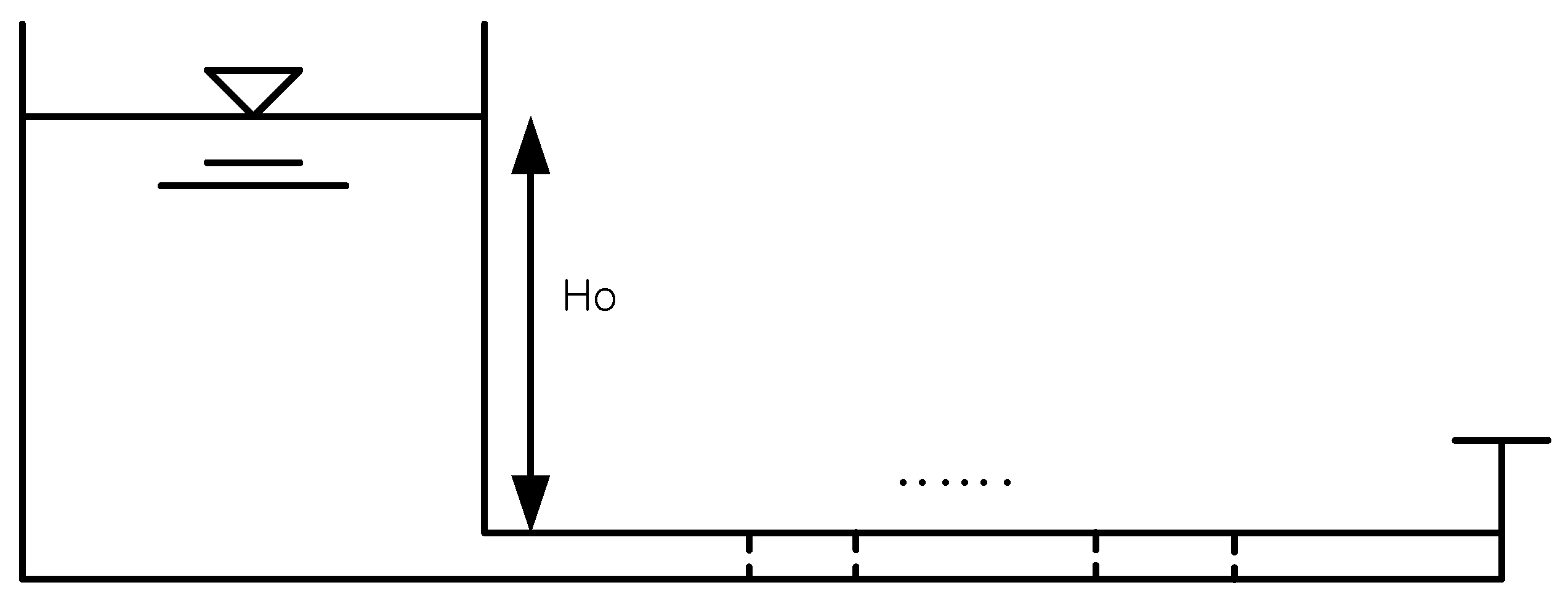
2.2. Complex Head and Discharge for a RPV System with Multiple Blockages
In order to define the impedance, the complex head to discharge must be determined along the pipeline (
Figure 1). Multiple blockages were introduced into a reservoir pipeline valve (RPV) system as shown in
Figure 1. Implementing a point matrix for partial blockage [
5,
6] into governing Equations (1) and (2), the expressions of complex head and discharge at the downstream valve for the multiple blockage condition can be derived as:
where,
is mean head loss for
ith blockage to the mean discharge,
, the propagation constants
and
can be defined as
,
m = (
ak2)/(2
gA),
, and
L = (
1 + k1)/(
gA); where
k1 and
k2 are the unsteady friction coefficients for the temporal and convective acceleration terms, respectively, and the characteristic impedances are
.
If Equations (3) and (4) are used for the friction model for laminar flow, expressions of complex head and discharge are
where, the propagation constant and the characteristic impedance are
(where
s is frequency and
D is a diameter), and
(where
i is the imaginary unit, and
J0 and
J1 are the first-type Bessel functions of the zeroth and first orders, respectively).
2.3. MDBF for the Frequency Dependent Friction Model
If one blockage is assumed for the pipeline system in
Figure 1, the hydraulic impedance for the 2-D models described in Equations (3) and (4) can be expressed as a ratio of the complex head and discharge as,
Equation (7) can be decomposed into three distinct terms of dimensionless hydraulic impedance (
,
,
) by dividing the complex discharge terms of the pipeline segments in an RPV system as,
A similar expression can be used for a RPV system with multiple blockages, namely the multiple discrete blockage function (MDBF) for frequency dependent friction, which can be expressed as,
where,
is a distance from the downstream valve to any upstream
ith blockage, and
is the
ith pressure head reduction.
3. Example Applications with Discussion
3.1. Hypothetical RPV System with Multiple Blockages
A hypothetical pipeline system with multiple blockages was assumed under a condition of steady pressure (
Figure 1). The length of the pipeline was 110 m and the internal diameter 0.02 m. The theoretical wave speed was assumed to be 1395 m/s and the steady flow rate was 4.71 × 10
−5 m
3/s. The steady pressure head was 23.2 m, and the kinematic viscosity of the water was 1.0 × 10
−6 m
2/s. The unsteady friction coefficients
k1 and
k2 for the 1-D model were assumed to be 0.0345, based on an experimental study by [
4]. The number of blockage was assumed to vary from one to ten. Distances for blockage number 1, 2, and 10 were 100 m, 90 m and 10 m from the downstream valve. Assuming the ratio of inner diameter of pipeline and partial blockage is ‘3’, the blockage constant was determined to be 225.
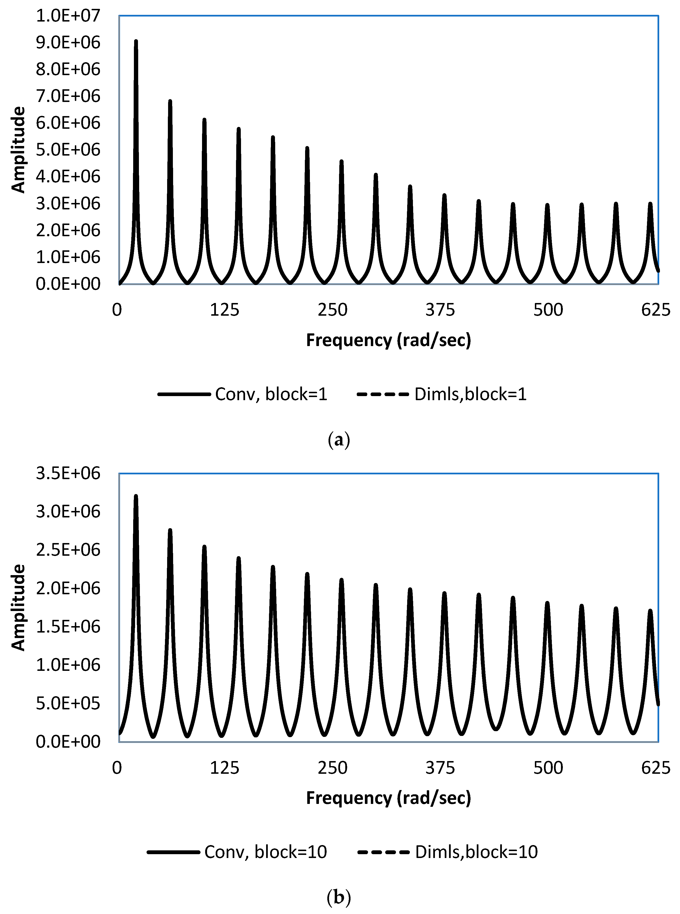
3.2. Frequency Domain Amplitude between the Conventional Method and MDBF
In order to compute the amplitude of the impedance response at the downstream valve, the maximum frequency for the frequency domain analysis was specified as 625 rad/s, and the number of samples for Fast Fourier Transformation was determined to be 8192, considering a balance between accuracy and computational cost.
Hydraulic impedances can be evaluated using a conventional method presented in Equation (6), or by proposed formulations that employ MDBF (such as Equations (9) for the assumption of frequency-dependent friction).
Figure 2a shows the amplitudes of the hydraulic impedance of the frequency dependent friction model for one blockage (100 m from the downstream valve) estimated using the existing method and then using the MDBF. This indicates that the difference between the traditional method and the proposed formulation was negligible. The amplitudes of hydraulic impedance of a frequency-dependent unsteady friction model for ten blockages (100–10 m at 10 m intervals) showed no difference between the conventional and the MDBF approaches (
Figure 2b).
Figure 3a shows the amplitudes of the hydraulic impedances computed by the conventional method and the MDBF using the acceleration-based unsteady friction model for one blockage (100 m from the downstream valve).
Figure 3b presents similar frequency responses for ten (100–10 m) blockages evaluated using the conventional method, and the MDBF. The amplitudes in
Figure 2b and
Figure 3b indicate that the impact of multiple blockages appeared to be greatly increased with the number of blockages. All analyses indicated that there was negligible difference between the conventional approaches and the formulations using MDBF. Further extensive tests (e.g., the steady friction model and other combinations of blockage conditions, blockage number, and blockage constant) provided almost identical results between the conventional and MDBF approaches.
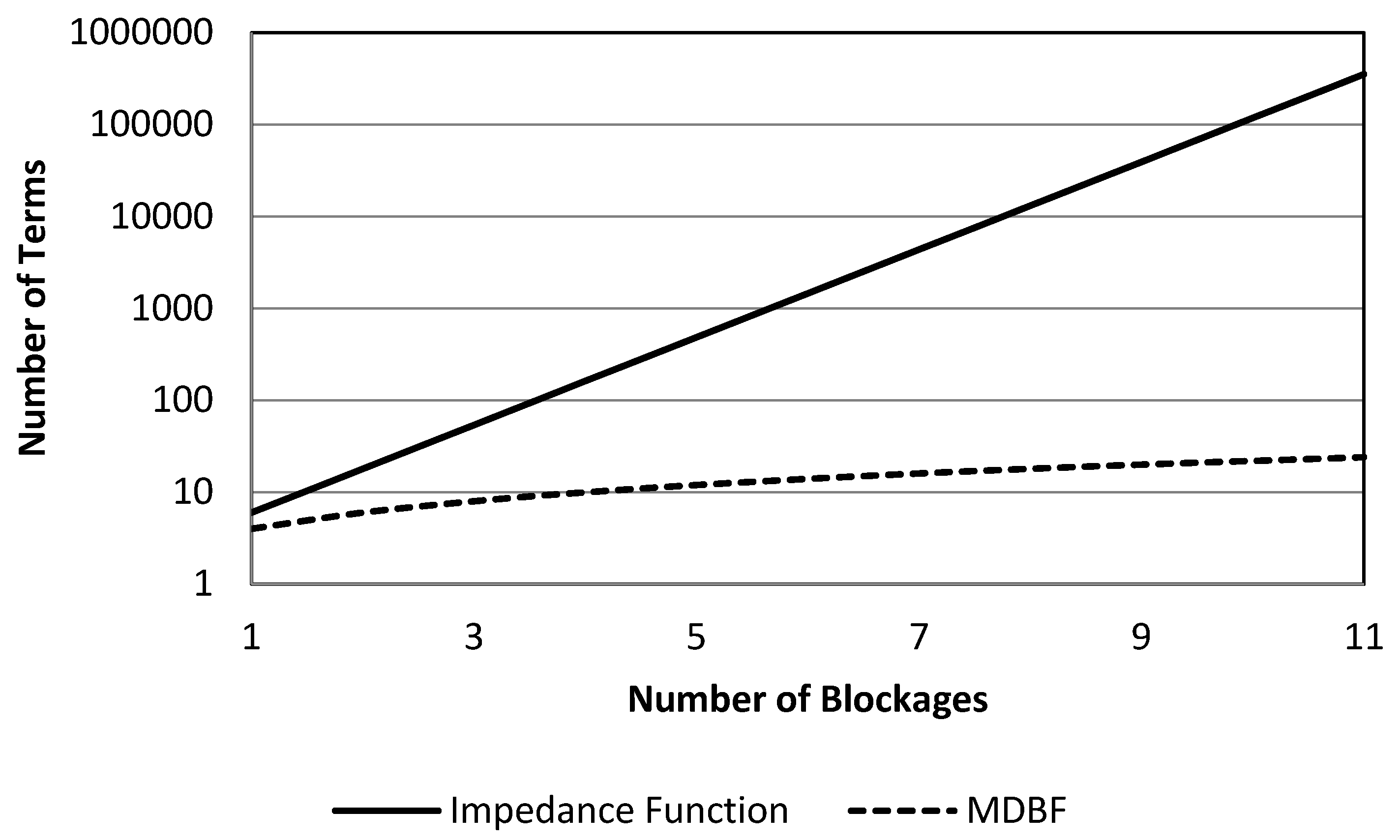
3.3. Strengths of the MDBF
Model Parsimony
One distinctive strength of the MDBF compared with the conventional formulation is the parsimony of the representation of multiple blockages for a RPV system. Two distinct wave propagation characteristics of the acceleration-based unsteady friction model introduce substantial complexity into formulations of pressure and discharge in the frequency domain. This makes the consideration of multiple partial blockages even more complicated. For instance, the number of terms for three partial blockages in a RPV system (within the traditional transfer function matrix) is 54 for the frequency-dependent unsteady friction model, respectively. Regardless of the number of partial blockages, MDBF formulations (such as Equation (9)) can feasibly address multiple blockage condition.
Figure 4 present the number of terms for the hydraulic impedance at the downstream valve using the traditional method and the MDBF for the frequency-dependent-unsteady model. While the traditional formulations show exponential incremental patterns as the number of blockages increased, the complexity of MDBF is substantially limited due to the structure of Equations (9). Improvement of model parsimony in the mathematical expressions for 11 blockage conditions between two different approaches, are of the 6th order for the frequency dependent unsteady-friction model.
4. Conclusions
Blockage detection is a technical issue important for the proper management of water distribution systems. Efficient representation of multiple blockages is an unexplored topic in pipeline modelling simply because inverse transient analysis for multiple abnormality conditions had been recognized as quite challenging. This study proposes a breakthrough, namely the use of the multiple discrete blockage function (MDBF), in the representation of multiple blockage conditions to reduce the complexity of the existing method in considering a large number of blockages. The MDBF showed frequency responses identical to those from existing methods under conventional conditions, such as number of blockages between 1 and 10, for both the frequency-dependent and the acceleration-based unsteady-friction models. Compared to traditional impedance approaches, the MDBF provided outstanding performance in terms of model parsimony.
