1. Introduction
Orthotropic steel decks used in road bridges are often employed in long-span bridges over straits and urban expressways because they are lightweight and easy to construct. In recent years, several types of fatigue cracks have occurred due to accumulated heavy vehicle traffic, among which through-bead cracks (fatigue cracks) at the welds between U-ribs and deck plates have been reported frequently. Early detection of through-bead cracks is important because, if left unchecked, they can propagate into the deck plate or U-rib base metal, leading to major damage to the orthotropic steel deck.
The Honshu-Shikoku Bridge Expressway Co., Ltd. has developed a crack detection system with infrared thermography and has been conducting inspections of actual bridges for approximately eight years, aiming at the practical application of the temperature gap method, which is a low-cost and efficient inspection method [
1]. The development of the fatigue crack detection system and the inspection results are described.
2. Detection Principle and Comparison with Conventional Methods
2.1. Detection Principle
Figure 1a shows a schematic diagram of the principle of detecting through-bead cracks by the temperature gap method. Solar radiation conducts heat from the pavement surface to the deck plate and U-rib. When a crack exists in the weld, the micro voids formed in the crack impede heat conduction, resulting in a temperature difference (temperature gap) compared to the normal area. By visualizing the temperature gap with infrared thermography imaging, the presence of cracks can be detected nondestructively and without contact.
Figure 1b is an infrared thermographic temperature image of the location of a through-bead crack. The temperature line profiles of the normal area (A-B-line) and the cracked area (a-b-line) on the image are illustrated at the bottom of the image. In the temperature line profile of the cracked area (a-b-line), heat conduction is disturbed before and after the through-bead crack, and the temperature drops after the crack. In the normal area (A-B-line), the temperature gradually drops from the weld to the U-rib. On the temperature image, there is a temperature drop area that is displayed in black from the crack to the U-rib, which clearly shows the difference from the normal area.
2.2. Comparison with Conventional Methods
In conventional inspection methods, the presence or absence of through-bead cracks is confirmed by close visual inspection, paint removal, and magnetic particle testing. Some inspection locations require temporary scaffolding, making inspections expensive and inefficient.
On the other hand, in inspections by the temperature gap method, infrared thermography is used to detect cracks by remotely capturing images, eliminating the need for close visual inspection, scaffolding installation, and paint removal, thereby enabling low-cost, efficient inspections.
3. Development of Inspection Equipment Suitable for Each Bridge
The total length of orthotropic steel deck lanes owned by the Honshu-Shikoku Bridge Expressway Co., Ltd. is about 100 km, which is enormously long, and thus it is necessary to develop inspection equipment and other means to efficiently perform inspections. The inspection and maintenance vehicles (hereafter referred to as ‘maintenance vehicles’) are permanently installed on each long-span bridge. However, their structure, operating mechanism, and positioning relationship to the weld beads significantly depend on the bridges, and customized temperature gap method devices for each specific bridge have been developed.
3.1. Method of Fixing the Instruments on the Maintenance Vehicle and Capturing Images
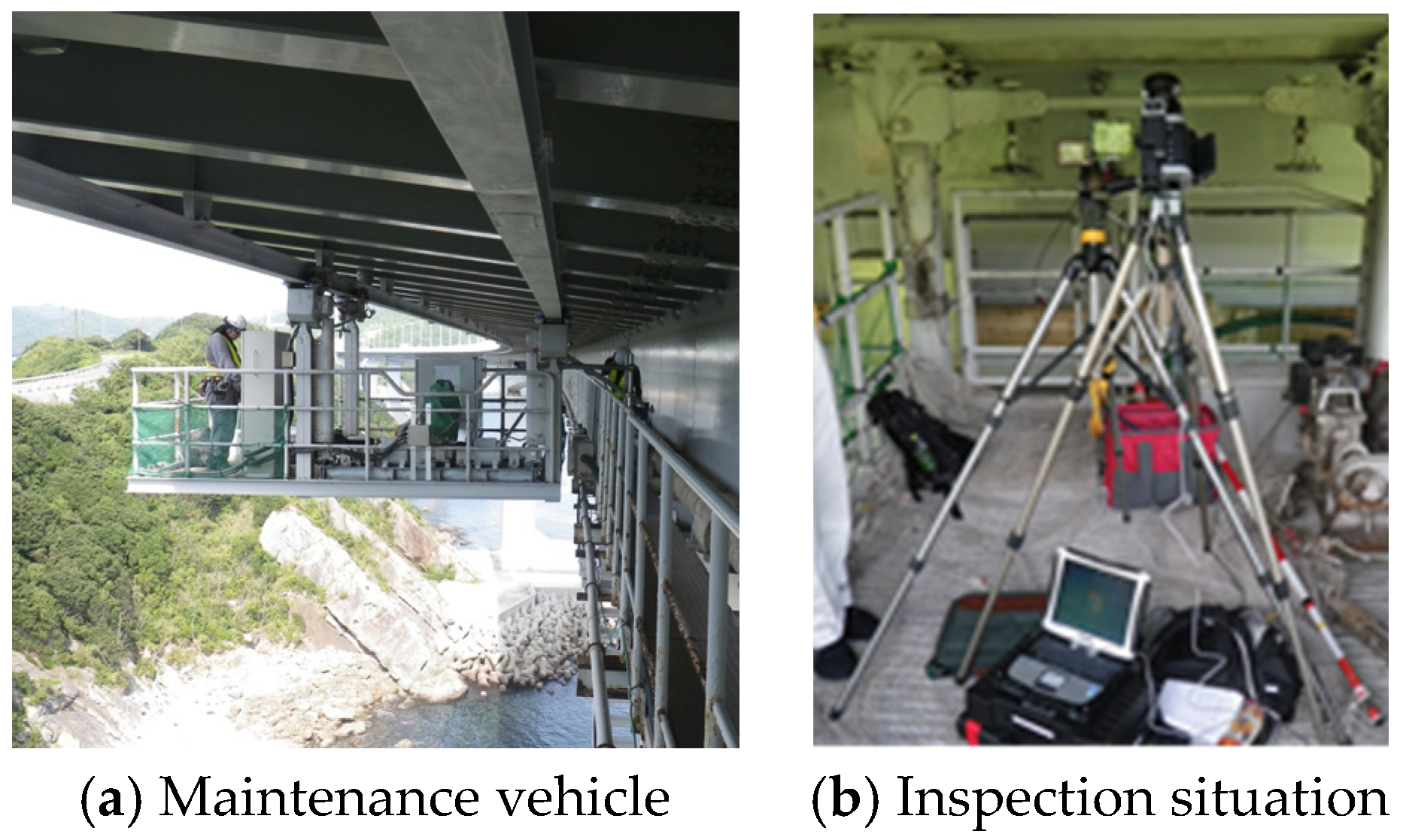
For bridges where the maintenance vehicle shown in
Figure 2a can run continuously in the direction of the bridge axis, the inspection is performed by running the maintenance vehicle equipped with inspection equipment. Since the direction of movement of the maintenance vehicle is the same as the direction of the weld beads, this method allows continuous capturing of images over a long length and efficient inspection.
3.2. Guide Rail System
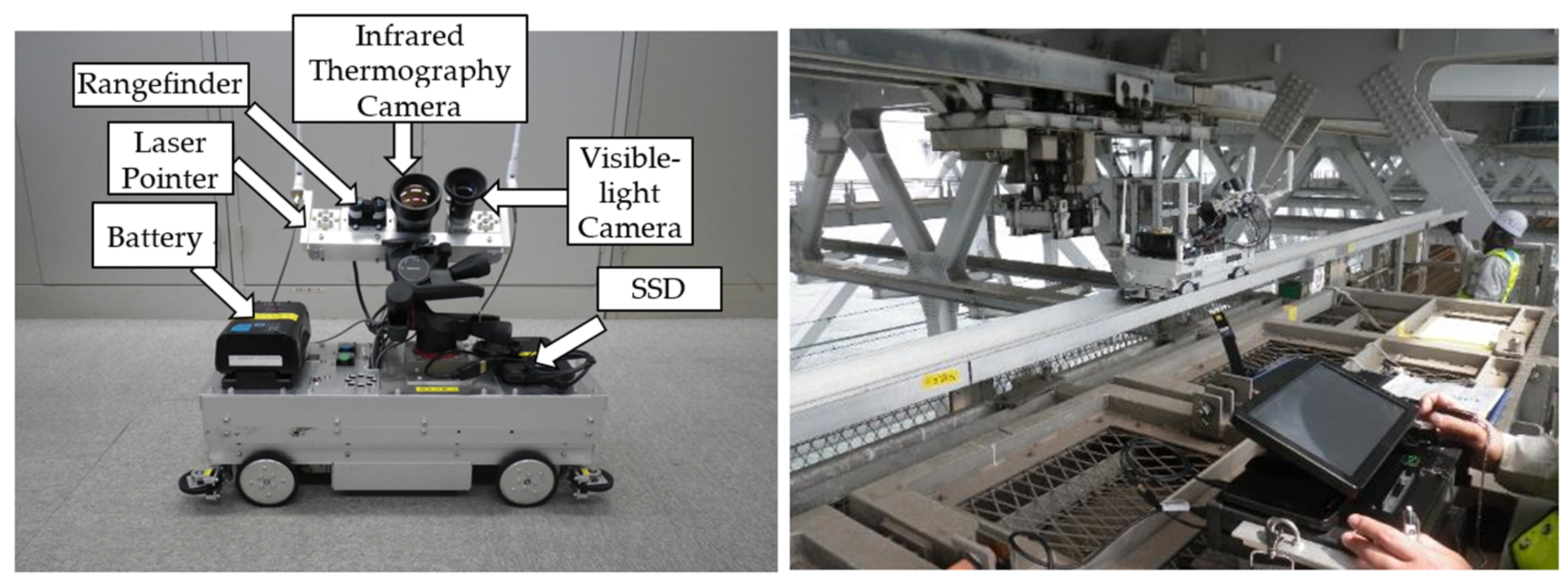
Since the maintenance vehicle is installed between the truss nodes on truss suspension bridges, etc., which are approximately 12 m apart, a guide rail system (
Figure 3) has been developed in which the inspection is performed by making the inspection equipment run on its own on the special guide rails installed on the maintenance vehicle. This method enables efficient inspections by running the inspection equipment on the guide rails by remote control for continuous capture of images, and is the most commonly used method on the Honshu-Shikoku Bridge Expressway.
3.3. Image Capturing System near the Stringer
In areas where the inspection zone is near the orthotropic steel deck stringer, applying the guide rail system described in
Section 3.2 is challenging due to limited space for equipment installation. To address this, a jig has been developed that enables the inspection device to travel along the lower flange of the stringer, and an image-capturing system near the stringer (
Figure 4) has been made for continuous image capture along the bridge axis. This system allows manual movement of the device along the stringer while capturing images continuously.
3.4. Equipment for Capturing Images from the Inspection Path
In bridges where only the inspection path shown in
Figure 5 is installed, there are many weld beads that cannot be inspected from the inspection path. For such bridges, a system is currently being developed in which the inspection can be performed by installing an arm on the handrail of the inspection path and mounting a camera head with a swiveling function on the end of the arm to use the infrared camera to inspect the blind weld beads (
Figure 6), with the aim of implementing the system on actual bridges.
4. Development of Automatic Crack Detection Software
Initially, cracks were detected by manually checking the images captured by the inspection equipment. However, in order to reduce the workload and improve the consistency of judgments among the inspectors, an automatic crack detection software has been developed to automatically detect cracks from the temperature images captured continuously [
2]. Since fiscal 2015, efficient and accurate inspections have been conducted using automatic crack detection software for primary screening, followed by expert review based on infrared inspection techniques.
5. Inspection Results at the Honshu-Shikoku Bridge Expressway
Many bridges in the Honshu-Shikoku Bridge Expressway need considerable time for inspection, even with advanced techniques using the temperature gap method. The inspections are conducted after prioritizing objects considering various conditions such as the orthotropic steel deck’s structural details (e.g., weld penetration) which are highly correlated with the initiation and propagation of through-bead cracks, fabrication date, and the accumulated heavy vehicle traffic.
From fiscal 2015 to 2022, nine bridges were inspected using the temperature gap method, covering about 130 km of welds—approximately 90% of the total target length (
Table 1). Although through-bead cracks were found on only two bridges, regular inspections remain necessary due to the risk of new fatigue cracks from ongoing heavy vehicle traffic.
6. Summary
The temperature gap method is a remote, non-contact, and efficient method for detecting through-bead cracks in orthotropic steel deck U-rib welds without the need for paint removal or scaffolding installation. Furthermore, to accommodate the different structural details and inspection environments of each bridge, specialized equipment was developed such as a guide rail system, an image capturing system near the stringer, and introduced software to automatically detect cracks, allowing for application to actual bridges. The developing work will be continued to respond to a greater variety of areas to be inspected and to improve inspection accuracy and efficiency.
Author Contributions
Conceptualization, H.T.; methodology, H.T. and Y.M.; software, H.T. and T.O.; validation, H.T. and H.K.; formal analysis, Y.M.; investigation, Y.M. and T.O.; resources, Y.M.; data curation, H.T. and T.O.; writing—original draft preparation, H.T.; writing—review and editing, Y.M., T.O. and H.K.; visualization, H.T.; supervision, H.T.; project administration, H.T.; funding acquisition, Y.M. All authors have read and agreed to the published version of the manuscript.
Funding
This research received no external funding.
Institutional Review Board Statement
Not applicable.
Informed Consent Statement
Not applicable.
Data Availability Statement
No new data were created or analyzed in this study. Data sharing is not applicable to this article.
Acknowledgments
This research was conducted in collaboration with Kobe University, the University of Shiga Prefecture, and the JB Honshu-Shikoku Bridge Expressway Group. This paper summarizes the results of the temperature gap method and the development of related equipment and systems for practical application. The authors sincerely thank all involved for their generous support.
Conflicts of Interest
H.T., T.O. and H.K. were employed by Honshi-Expressway Bridge Engineering Co., Ltd. Y.M. was employed by Honshu-Shikoku Bridge Expressway Co., Ltd.
References
- Mizokami, Y.; Kobayashi, Y.; Izumi, Y.; Sakagami, T. Remote NDT technique for through-weld crack in orthotropic steel deck by temperature gap measurement using infrared thermography. J. Steel Constr. Eng. 2015, 22, 47–56. [Google Scholar] [CrossRef]
- Yoshiaki, M.; Atsuhiro, O.; Tokihide, O.; Yui, I.; Takahide, S. Development of automatic crack detection device for bead-penetrating crack in orthotropic steel deck by temperature gap method using infrared thermography. J. Struct. Eng. 2018, 64, 573–582. [Google Scholar] [CrossRef]
| Disclaimer/Publisher’s Note: The statements, opinions and data contained in all publications are solely those of the individual author(s) and contributor(s) and not of MDPI and/or the editor(s). MDPI and/or the editor(s) disclaim responsibility for any injury to people or property resulting from any ideas, methods, instructions or products referred to in the content. |
© 2025 by the authors. Licensee MDPI, Basel, Switzerland. This article is an open access article distributed under the terms and conditions of the Creative Commons Attribution (CC BY) license (https://creativecommons.org/licenses/by/4.0/).


