A Flexible Pad-Printed Fluxgate Sensor †


University of Applied Sciences and Arts Western Switzerland (HES-SO), Geneva, Switzerland
*
Author to whom correspondence should be addressed.
†
Presented at the Eurosensors 2017 Conference, Paris, France, 3–6 September 2017.
Proceedings 2017, 1(4), 615; https://doi.org/10.3390/proceedings1040615
Published: 8 August 2017
(This article belongs to the Proceedings of Proceedings of Eurosensors 2017, Paris, France, 3–6 September 2017)
Abstract
:A flexible flat micro-Fluxgate sensor with amorphous rectangular core, fabricated using a simple printing technique is presented. All materials were selected to facilitate the fabrication process and to achieve optimal sensor performance. The device’s response to an externally applied magnetic field has been studied. The linear measuring range of the sensor is approximately ±40 μT with a linearity error of <2% FS at 100 kHz excitation frequency, allowing the measurement of the terrestrial magnetic field. Experimental results demonstrate that the behaviour of the fabricated device corresponds to the behaviour of a Fluxgate sensor with high sensitivity.
1. Introduction
Fluxgate sensors are devices capable of measuring the magnetic flux density of weak magnetic fields with very high accuracy. They are vector instruments, a fact that makes them ideal for compass applications. For simple applications that do not require precision and high resolution, they have recently been replaced by anisotropic magnetoresistance sensors (AMR) due to their complicated fabrication techniques [1]. Many efforts have been made to simplify fluxgates’ fabrication techniques by using either printed circuit board (PCB) technologies [2,3,4] or other microengineering technologies based on silicon [5,6]. With the transition to silicon process technology, fluxgate sensors inherited the interesting features of microfabrication, as predicted in [7]. New developments on various printing techniques created the possibility for fluxgate sensors and other microfabricated devices to obtain various attractive characteristics, such as flexibility, ease of integration, environmental friendliness etc.
Recently simple printing techniques have become more appealing. They allow rapid manufacturing and the overall production processes are relatively simple. Printed electromechanical systems (PEMS) have already been introduced into the market in the form of inexpensive devices such as electrodes, printed displays, RFID tags, printed sensors and other applications presented in [8].
2. Materials and Methods
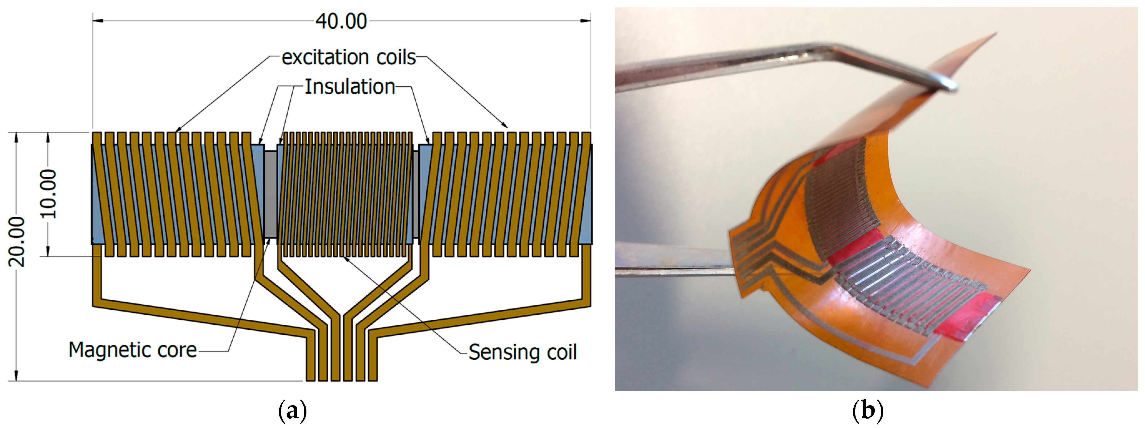
The design of the sensor was mainly influenced by the chosen fabrication technique. A typical Fluxgate sensor consists of a soft ferromagnetic core, excitation coils and a sensing coil wound around the core [1]. Thus a simplified “bar design” (shown in Figure 1a) with solenoid coils was adopted to facilitate the fabrication process.
The sensor consists of five main layers: two conductive layers, two insulating layers and the magnetic core. For the magnetic core, “Vitrovac 6025 Z®” was selected for its high permeability. Furthermore, the magnetic core is a component glued on the printed layers. The role of the conductive layers is to form the solenoids, while the insulating layers insulate the magnetic core from the coils.
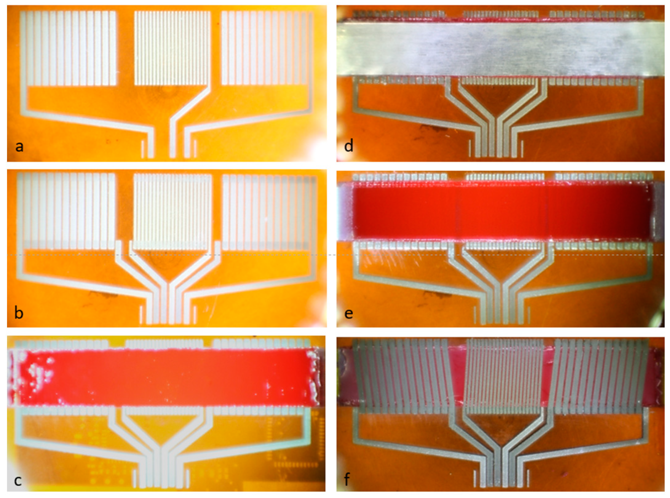
Since Pad-printing is an additive fabrication technique and the ink layers used remain flexible, the choice of Kapton® (polyamide film) with 127 μm thickness as substrate was made. The results of the printing steps are shown in Figure 2. The first print consists of the bottom conductive layer of the solenoid coils. The polymerization of the inks is achieved by a thermal treatment following each print. For the first two prints a treatment of 1 h at 180 °C was applied. The second print consists of the conductive vias that help to overcome the thicknesses of both the magnetic core and the insulation. The next print consists of the bottom insulating layer. From this point forward, thermal treatment of 2 h at 120 °C was applied after each print. The magnetic core was glued on the surface of the insulating layer. Then the entire insulation was obtained by printing walls laterally to the magnetic core and afterwards the top insulating layer. The addition of the top conductive print forms the solenoids.
After the fabrication process, the sensor is tested for sort-circuits with the magnetic core and the characteristics of the coils are measured. The excitation coils exhibit an average inductance value of 0.75 μH each, while the sensing coil exhibits 1.25 μH, measured at 100 kHz.
3. Experiments and Results
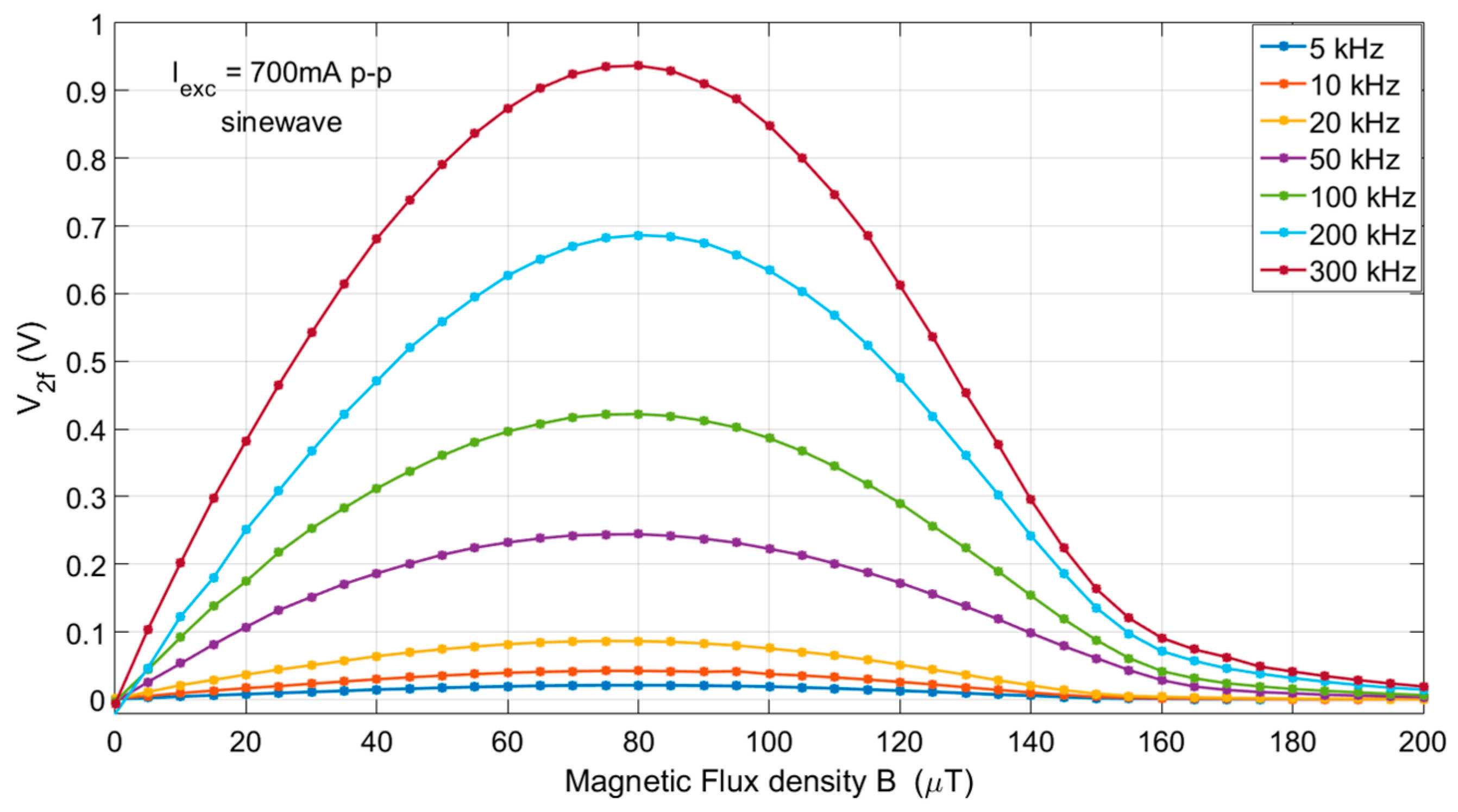
The working principle of the fabricated sensor is based on the periodic modulation of the soft magnetic core’s permeability. The excitation coils generate an AC magnetic field that saturates the core and causes an induced voltage on the sensing coil. Without any external magnetic field, the induced voltage is symmetrical and only odd harmonics are present in the waveform. If an external magnetic field is applied, this symmetry is disturbed and even harmonics appear in the induced voltage waveform [10]. The magnitude of the external field can be evaluated through its proportionality to the second harmonic of the induced voltage.
Several measurements were conducted to determine the sensing properties by placing the sensor at a flat (not curved) longitudinally to the magnetic field in a Helmholtz coil configuration. A wide range of excitation frequencies and sinusoidal excitation currents were applied using a signal generator with high output current limit. No capacitors were used for the excitation nor for the output tuning of the sensing coil.
Applying an excitation current of 700 mA p-p with frequencies 5–300 kHz demonstrated that the measuring linear range of the sensor is approximately ±40 μT with a linearity error of <2% FS at 100 kHz. The second harmonic sensor response (V2f) to the applied field is shown in Figure 3.
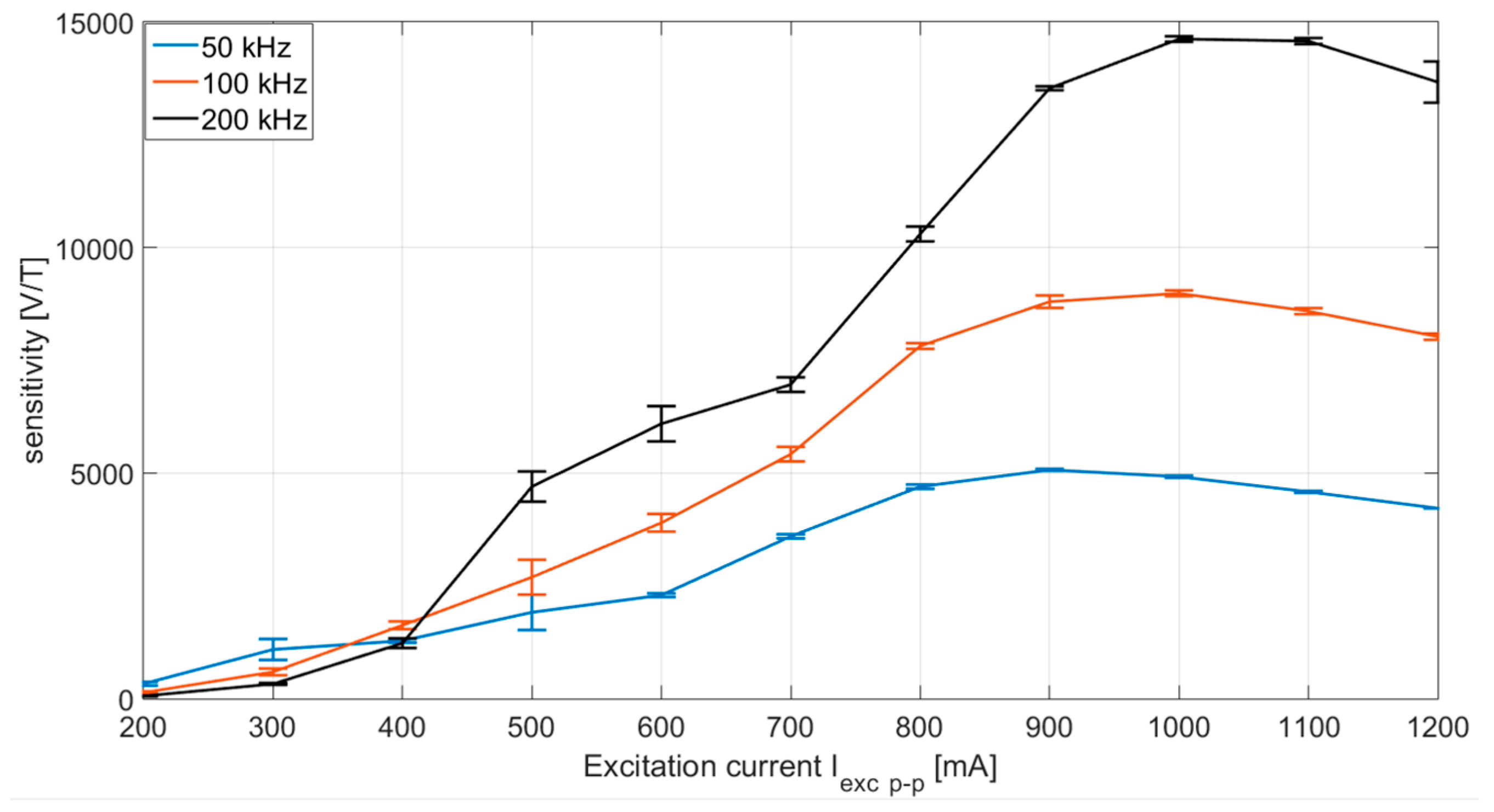
In Figure 4, the resulting sensitivity curves are presented as a function of the excitation current. The error bars on the curves show the repeatability and the stable operating points of the sensor. Sensor sensitivity increases with frequency and with current up to a certain limit, while the maximum values of the corresponding sensitivity are shifted due to eddy currents as reported in [2].
4. Discussion and Conclusions
We have presented a Fluxgate sensor fabricated using the Pad-printing technique. In contrast to other printing techniques, pad-printing made possible the inclusion of the magnetic core, a non-printed component, into the device. One possible application of this printing technique is the fabrication of PEMS devices on flat and curved surfaces as post-process.
The flexibility of the sensor is susceptible to offer new possibilities in sensing curved magnetic fields. Further work will allow us to study this property. Compared to other microfabricated sensors, sensitivity is among the highest reported. The power consumption of the sensor is high due to the resistivity of the conductive inks, which is 40 times higher than that of pure silver. Further advances in material research and ink formulation are expected to improve ink conductivity, thus minimizing the excitation currents
Acknowledgments
The authors would like to thank VACUUMSCHMELZE (www.vacuumschmelze.de) for their technical advice and support.
Conflicts of Interest
The authors declare no conflict of interest.
References
- Ripka, P. Review of fluxgate sensors. Sens. Actuators A 1992, 33, 129–141. [Google Scholar] [CrossRef]
- Kubik, J.; Pavel, L.; Ripka, P. PCB racetrack fluxgate sensor with improved temperature stability. Sens. Actuators A 2006, 130–131, 184–188. [Google Scholar] [CrossRef]
- Kejı́k, P.; Chiesi, L.; Janossy, B.; Popovic, R. A new compact 2D planar fluxgate sensor with amorphous metal core. Sens. Actuators A: Phys. 2000, 81, 81–180. [Google Scholar] [CrossRef]
- Dezuari, O.; Belloy, E.; Gilbert, S.; Gijs, M. Printed circuit board integrated fluxgate sensor. Sens. Actuators A 2000, 81, 200–203. [Google Scholar] [CrossRef]
- Liakopoulos, T.; Ahn, C. A micro-fluxgate magnetic sensor using micromachined planar solenoid coils, Sens. Actuators A 1999, 77, 66–72. [Google Scholar] [CrossRef]
- Chiesi, L.; Kejik, P.; Janossy, B.; Popovic, R. CMOS planar 2D micro-fluxgate sensor. Sens. Actuators A 2000, 82, 174–180. [Google Scholar] [CrossRef]
- Kawahito, S.; Satoh, H.; Sutoh, M.; Todokoro, Y. High-resolution micro-fluxgate sensing elements using closely coupled coil structures. Sens. Actuators A 1996, 54, 612–617. [Google Scholar] [CrossRef]
- Lee, T.M.; Choi, H.C.; Noh, J.H.; Kim, D.S. EL Display Printed on Curved Surface. In Proceedings of the 2009 IEEE 22nd International Conference on Micro Electro Mechanical Systems, Sorrento, Italy; 2009; pp. 943–946. [Google Scholar] [CrossRef]
- Krebs, F. Pad printing as a film forming technique for polymer solar cells. Sol. Energy Mater. Sol. Cells 2009, 93, 484–490. [Google Scholar] [CrossRef]
- Ripka, P. Advances in fluxgate sensors. Sens. Actuators A 2003, 106, 8–14. [Google Scholar] [CrossRef]
Figure 1.
Fluxgate sensor: (a) Schematic diagram of the fluxgate sensor with dimensions in mm; (b) picture of the flexible pad-printed fluxgate sensor with total thickness less than 300 μm.
Figure 1.
Fluxgate sensor: (a) Schematic diagram of the fluxgate sensor with dimensions in mm; (b) picture of the flexible pad-printed fluxgate sensor with total thickness less than 300 μm.

Figure 2.
Printing steps of the sensor: (a) First print: bottom conductive layer; (b) Second print: Conductive vias; (c) Third print: bottom insulating layer; (d) Mounting and attachment of magnetic core; (e) Fourth print: top insulating layer; (f) Fifth print: top conductive layer.
Figure 2.
Printing steps of the sensor: (a) First print: bottom conductive layer; (b) Second print: Conductive vias; (c) Third print: bottom insulating layer; (d) Mounting and attachment of magnetic core; (e) Fourth print: top insulating layer; (f) Fifth print: top conductive layer.

Figure 3.
Second harmonic sensor response to applied field for various excitation frequencies.

Figure 4.
Sensor sensitivity as a function of excitation current for three different frequencies.

Publisher’s Note: MDPI stays neutral with regard to jurisdictional claims in published maps and institutional affiliations. |
© 2017 by the authors. Licensee MDPI, Basel, Switzerland. This article is an open access article distributed under the terms and conditions of the Creative Commons Attribution (CC BY) license (https://creativecommons.org/licenses/by/4.0/).
Share and Cite
MDPI and ACS Style
Schoinas, S.; Guamra, A.-M.E.; Moreillon, F.; Passeraub, P. A Flexible Pad-Printed Fluxgate Sensor. Proceedings 2017, 1, 615. https://doi.org/10.3390/proceedings1040615
AMA Style
Schoinas S, Guamra A-ME, Moreillon F, Passeraub P. A Flexible Pad-Printed Fluxgate Sensor. Proceedings. 2017; 1(4):615. https://doi.org/10.3390/proceedings1040615
Chicago/Turabian StyleSchoinas, Spyridon, Adyl-Michaël El Guamra, Fabien Moreillon, and Philippe Passeraub. 2017. "A Flexible Pad-Printed Fluxgate Sensor" Proceedings 1, no. 4: 615. https://doi.org/10.3390/proceedings1040615