Proceeding Paper

Linear Integrated Interface for Automatic Differential Capacitive Sensing †

by
Gianluca Barile
1,*,
Giuseppe Ferri
1,
Francesca Romana Parente
1,
Vincenzo Stornelli
1,
Alessandro Depari
2,
Alessandra Flammini
2 and
Emiliano Sisinni
2
1
Department of Industrial and Information Engineering and Economics, University of L’Aquila, 67100 L’Aquila, Italy
2
Deparment of Information Engineering, University of Brescia, 25123 Brescia, Italy
*
Author to whom correspondence should be addressed.
Presented at the Eurosensors 2017 Conference, Paris, France, 3–6 September 2017.
Proceedings 2017, 1(4), 592; https://doi.org/10.3390/proceedings1040592
Published: 29 August 2017
(This article belongs to the Proceedings of Proceedings of Eurosensors 2017, Paris, France, 3–6 September 2017)

Abstract

:
In this work, the authors introduce a new full-analog front-end for differential capacitance sensors which provides a DC output voltage, directly proportional to the measurand variations. The readout circuit architecture is based on a De Sauty bridge as core of the capacitive sensing whereas the feedback circuitry performs the bridge autobalancing operation by means of changes in a multiplier output. The circuit is designed in a standard CMOS technology (AMS 0.35 µm) so is suitable for portable systems. Simulated results have shown a good agreement with the theoretical model being the percentage relative error less than 2.5%. Interface sensitivity is constant and values around 0.055 V/mm for the considered application.

1. Introduction

In the last decade, capacitive transducers have been gaining popularity, in particular in sensor applications [1]. Capacitive sensors are able to sense and evaluate changes in physical or chemical quantities of interest through the detection of capacitance variations related to modifications of the sensor geometry or in the dielectric material [2]. Capacitive sensor values can span over several decades depending on the application, even if in the recent past the large adoption of MEMS systems lowered the useful range from hundreds of picofarads to fractions of picofarads [3,4]. This kind of sensing is typically performed by an indirect measurement through suitable interface electronic circuits. In this sense, owing to the reduced size of the sensors, the need of a simple and easily integrable interface is of a fundamental importance. In addition, capacitive sensors do not have intrinsic power consumption, thus they can be used with relatively LP circuit techniques, giving them a wide variety of possible applications [5].
A differential capacitive sensor can be represented by a three-plate system (see Figure 1) as the series of two capacitors C1 and C2. The two capacitors change their value in a differential way under the action of the measurand [6], which usually is the linear position of the middle plate with respect to the rest central position in displacement sensors.
The measurand variation estimated by the dimensionless variable x can be expressed as follows:
x = C 1 C 2 C 1 + C 2
This behavior makes such a sensor suitable for many applications like displacement and acceleration detection, position measurement, etc. [7,8,9,10].
The presented interface results in a deep upgrade with respect to [11,12]. The architecture core still relies on a De Sauty bridge; however, thanks to a redesign of the feedback circuitry, two major improvements have been achieved: Input-Output linearization, and full range autobalancing region. Moreover, with respect to what presented in [12], a fully integrated low-voltage low-power design using a standard CMOS technology has been implemented.

2. The Proposed Interface

The proposed interface is shown in Figure 2. Each block has been designed at transistor level, in a standard CMOS technology. The performed measurement technique consists of a capacitance-to-voltage conversion. The structure hosting the differential sensor is a simple De Sauty bridge, where the left branch is the differential capacitive sensor, whilst the right one is composed by a mechanism which emulates a voltage divider with a VCR (Voltage Controlled Resistor) replacing one resistor of the divider. Generally speaking, an autobalancing strategy can be considered as a negative feedback-based system whose aim is to minimize or null a certain error signal, e.g., the bridge unbalance. In the proposed solution, the feedback circuitry maintains the bridge balance by adjusting the Modulator multiplier output, to produce a signal Va which tends to follow Vb, hence forcing the error signal ΔV = Va − Vb to zero. The feedback signal Vctrl is obtained by extracting the DC component of the error signal ΔV. This is achieved by synchronously demodulating ΔV performed with the Demodulator multiplier followed by a second order Sallen-Key filter, which removes the residual ripple and ensures a good dynamic response.
A straightforward analysis brings to the following analytical linear relation between the measurand x (defined as in Equation (1)) and the voltage Vctrl:
x = G m u l t k V c t r l 1
where Gmult is the total gain of the multipliers (that can be set varying the value of the two resistors Rg1 and Rg2) and k is a constant depending on both the multiplier design and on the used CMOS technology.
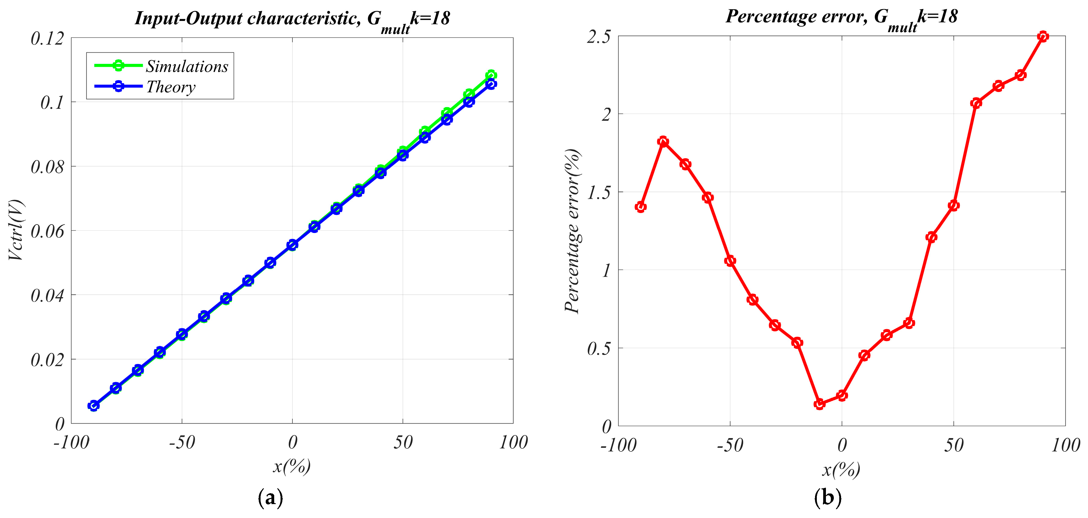
Figure 3a shows the Input-Output static characteristic of the interface. The product between Gmult and k has been set to Gmultk = 18, so obtaining a reduced punctual percentage relative error (<2.5%, see Figure 3b) of the simulated data with respect to the theoretical calculations. The curve in Figure 3a is widely contained within the supply voltage (output swing is limited by the multiplier linearity range), this means that no saturation is reached hence a complete ±100% autobalancing range is achieved.
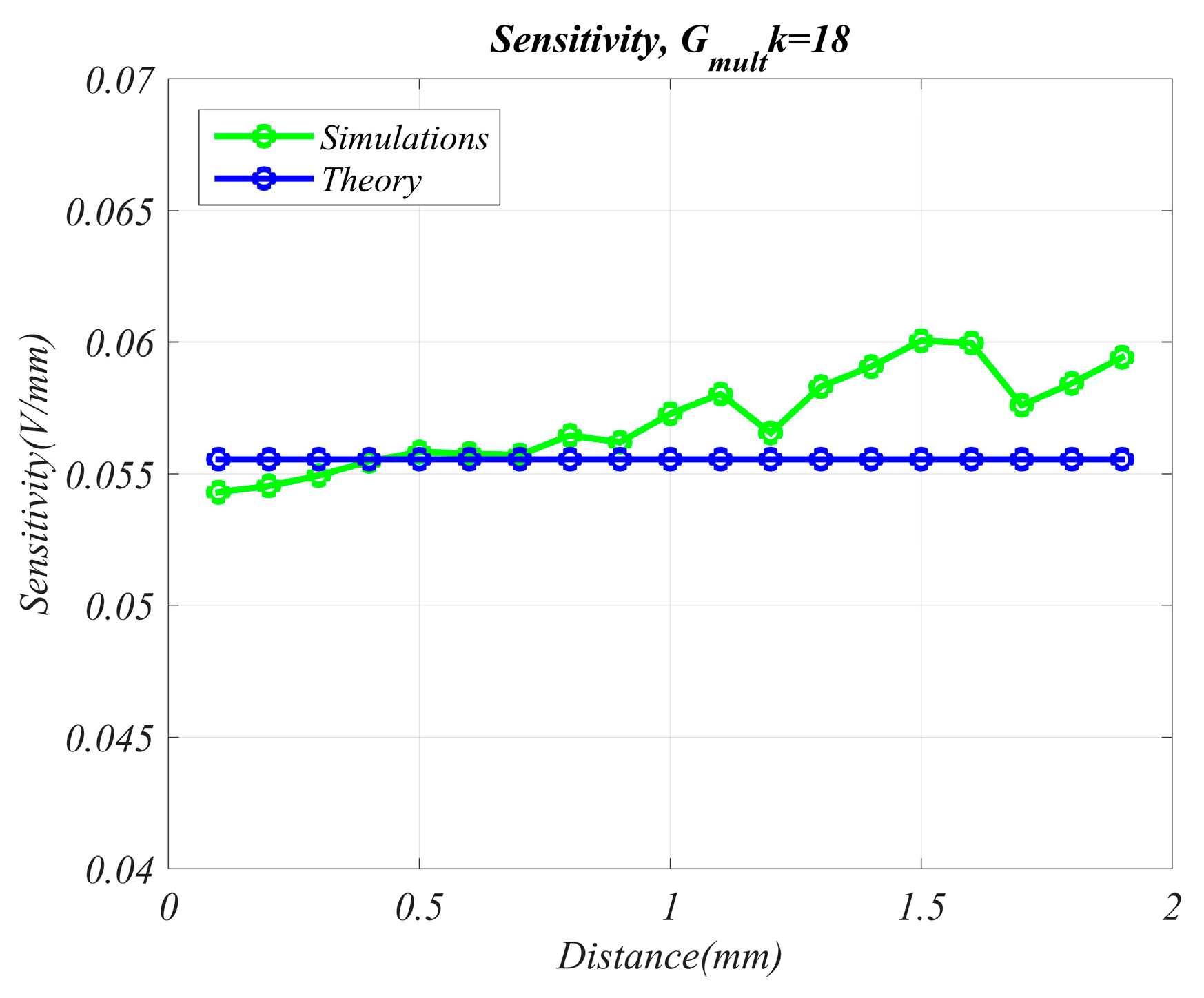
Sensitivity analysis has been performed in a displacement measurement application, where a typical baseline value (which corresponds to x = 0) has been set to 1 mm in Figure 4. Sensitivity is ideally constant (roughly 0.055 V/mm) and it slightly fluctuates around 0.058 V/mm in simulated results.

3. Conclusions

A fully integrated low-voltage low-power design using a standard CMOS technology is presented, showing a good agreement with theoretical and simulation results. This work overcomes the main issue of a previous similar solution, i.e., a non-linear relation between the output response and the measurand, providing a direct simple relationship between measurand variations and output voltage. Theoretical and simulated considerations have demonstrated the effectiveness of the proposed approach, confirming the circuit capability to allow a full estimation range.

Conflicts of Interest

The authors declare no conflict of interest.

References

  1. De Marcellis, A.; Ferri, G. Analog Circuits and Systems for Voltage-Mode and Current-Mode Sensor Interfacing Applications; Springer: Houten, The Netherlands, 2011. [Google Scholar]
  2. Baxter, K. Capacitive sensor basics. In Capacitive Sensors: Design and Applications; The Institute of Electrical and Electronics Engineers: New York, NY, USA, 1997; pp. 1–46. [Google Scholar]
  3. Ko, W.H. Trends and frontiers of MEMS. Sens. Actuators A Phys. 2007, 136, 62–67. [Google Scholar] [CrossRef]
  4. Kumar, B.; Rajita, G.; Mandal, N. A review on capacitive-type sensor for measurement of height of liquid level. Meas. Control 2014, 47, 219–224. [Google Scholar] [CrossRef]
  5. Puers, R. Capacitive sensors: when and how to use them. Sens. Actuators A Phys. 1993, A37–A38, 93–105. [Google Scholar] [CrossRef]
  6. Mochizuki, K.; Watanabe, K.; Masuda, T. A High-Accuracy High-Speed Signal Processing Circuit of Differential-Capacitance Transducers. IEEE Trans. Instrum. Meas. 1998, 47, 1244–1247. [Google Scholar] [CrossRef]
  7. Ferri, G.; Parente, F.R.; Stornelli, V. Analog current-mode interfaces for differential capacitance sensing. In Proceedings of the IEEE Sensors Applications Symposium (SAS), Catania, Italy, 20–22 April 2016; pp. 1–6. [Google Scholar]
  8. Lötters, J.C.; Olthuis, W.; Veltink, P.H.; Bergveld, P. A sensitive differential capacitance to voltage converter for sensor applications. IEEE Trans. Instrum. Meas. 1999, 48, 89–96. [Google Scholar] [CrossRef]
  9. George, B.; Kumar, V.J. Switched capacitor signal conditioning for differential capacitive sensors. IEEE Trans. Instrum. Meas. 2007, 56, 913–917. [Google Scholar] [CrossRef]
  10. Ferri, G.; Parente, F.R.; Stornelli, V.; D’Amico, A.; Pennazza, G.; Santonico, M. A standard CMOS technology fully-analog differential capacitance sensor front-end. In Proceedings of the IEEE International Workshop on Advances in Sensors and Interfaces (IWASI), Gallipoli, Italy, 18–19 June 2015; pp. 152–157. [Google Scholar]
  11. Ferri, G.; Stornelli, V.; Parente, F.R.; Barile, G. Full range analog Wheatstone bridge-based automatic circuit for differential capacitance sensor evaluation. Int. J. Circuit Theory Appl. 2016. [Google Scholar] [CrossRef]
  12. Ferri, G.; Parente, F.R.; Stornelli, V.; Barile, G.; Pantoli, L. Automatic bridge-based interface for differential capacitive full sensing. Procedia Eng. 2016, 168, 1585–1588. [Google Scholar] [CrossRef]
Figure 1. Differential capacitive sensor structure: (a) when the measurand influences the distance between plates; (b) when the measurand influences the overlapping area of plates.
Proceedings 01 00592 g001
Figure 2. The block scheme of the proposed readout circuit.
Proceedings 01 00592 g002
Figure 3. (a) Interface Input (x%)—Output (Vctrl) response; (b) % percentage relative error between theory and simulation.
Proceedings 01 00592 g003
Figure 4. Interface sensitivity vs. distance.
Proceedings 01 00592 g004
Publisher’s Note: MDPI stays neutral with regard to jurisdictional claims in published maps and institutional affiliations.