The system consists on two IMU sensors, wireless connected to a portable receiver (a smartphone) and/or directly to a PC collecting data for off-line processing and creating an individual electronic diary (e-diary). The system is depicted in
Figure 1. The direct wireless connection to the PC via the home Wifi is preferred in indoor application. The board is a prototype system-on-board designed for processing signals in real-time and transmitting them. The IMU integrates a ±16 g (g-force) 3D accelerometer, and a ±2000 dps 3D gyroscope. The Bluetooth V3.0 module uses the Serial Port Profile (SPP). The processing unit is an ultralow-power 32-bit microcontroller with 33.3 DMIPS peak computation capability and an extremely low power consumption scalable down to 233 uA/MHz. The board size is 25 × 30 × 4 mm
3 including the battery. An USB port is included for recharging battery. The PC makes off-line data processing, realizing a friendly interface with remote access to data in a cloud.
The algorithm is based on a time domain signal analysis. The raw signals of accelerometers and gyroscopes are fused together by using an orientation-estimation algorithm [
3]. The sampling frequency (
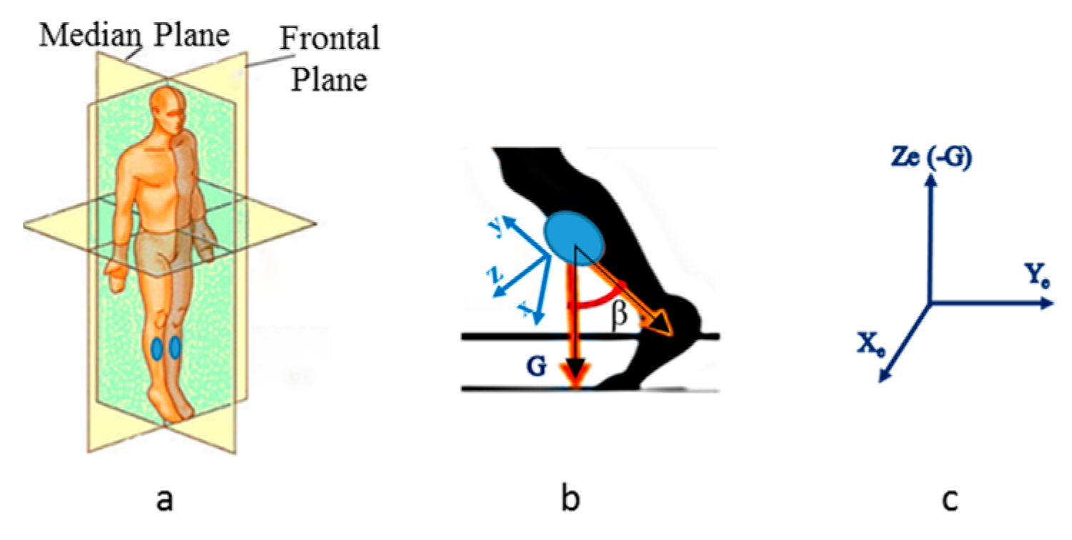
fs) is 60 Hz when a PC is used and 25 Hz when a smartphone is used. Two sensors are positioned on the shins. Gait direction is in the median plane of
Figure 2a. The x-y-z sensor reference system sketched in
Figure 2b rotates in the Xe-Ye-Ze earth reference system (
Figure 2c). Ze coincides with negative G axis. We focus onto the angle
β sketched in
Figure 2b. It is calculated as the angle formed between two 3D vectors: the negative y-axis and the gravity axis (G). Therefore, the angle
β is solid and we need to analyze its projection onto the median plane. Eventual discontinuities of the
β angle when it changes the sign, and consequent problems in angle derivation, can be easily overcome by conventional mathematical techniques. The algorithm calculates the first order low-pass filtered angular velocities
ωright,
ωleft obtained by
β derivation. We define with
ωt and
kt, respectively, the angular velocity and the lowpass filter measured at time t, with
kt-1 the
k value at the previous step, with
α the smoothing coefficient, with
fcutoff the cutoff frequency:
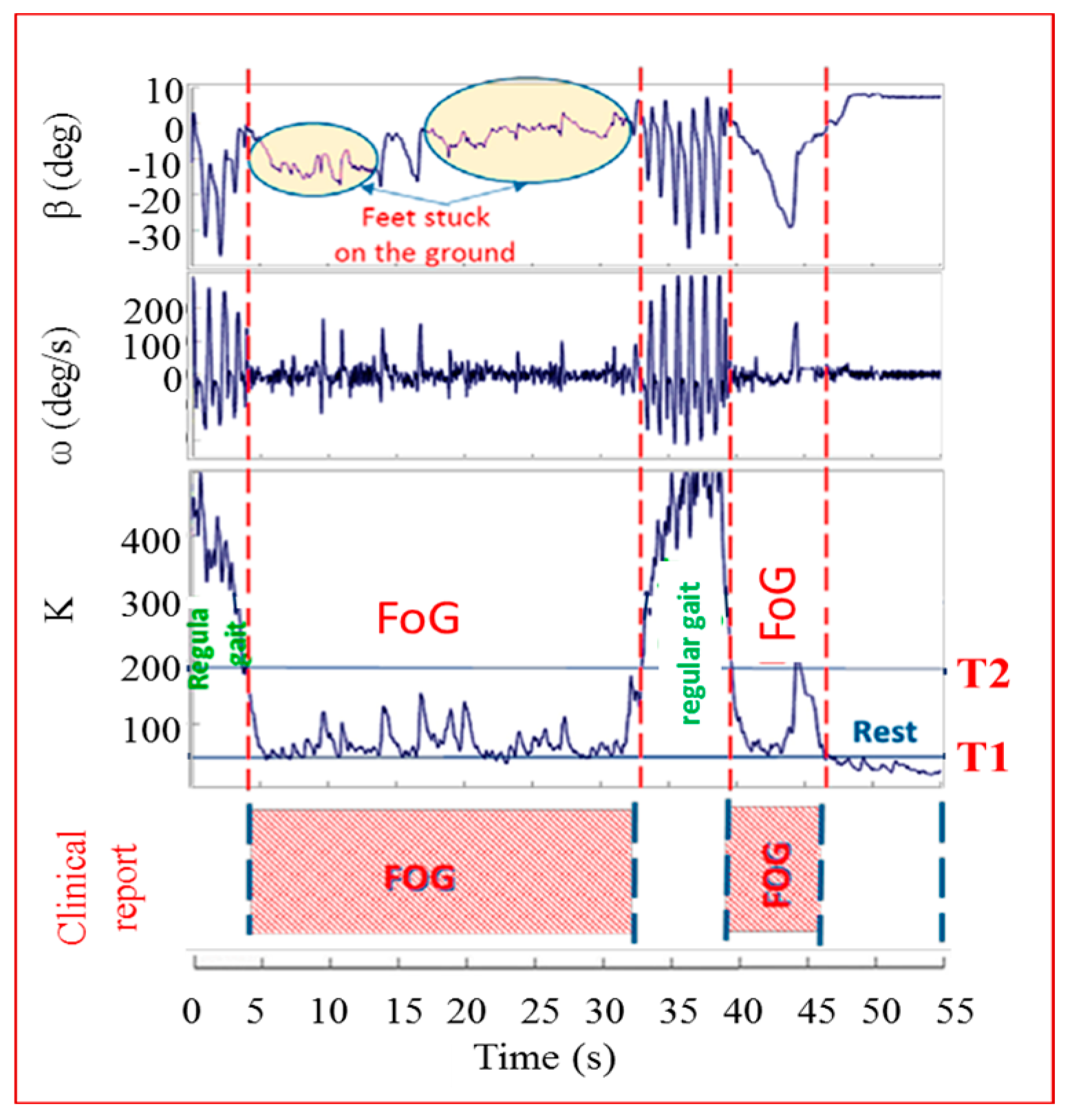
A group of 45 patients of different age, stage of disease and gender was asked to wear the sensors and walk some steps, turn and go back passing through an open door (which is a virtual obstacle inducing FoG). All the tests were filmed and the films were studied by doctors who determined the exact starting and ending times of the FoG episodes. Clinical reports represented our absolute reference. In
Figure 3 we can see how the algorithm works. In that test the patient was a female, over 65, in an advanced stage of the disease. The behavior of
β,
ω and
K are shown as function of the test time. As one can see, the
β and
ω curves varied consistently with time. In particular, it is easy to appreciate an oscillatory behavior of
β and
ω during the regular gait (0–4 s; 32–39 s) and a flatness during the rest state (46–55 s). The clinical report about the exact FoG timing is indicated in the figure bottom. Doctors referred the occurrence of two FoG episodes, in 4–32 s and 39–46 s. The comparison between the
K index and the clinical report allowed defining the T thresholds for the three states classification, as reported in the figure: regular gait (
K > T2), FoG state (T2 >
K > T1) and rest state (
K < T1). Once the values of T1–T2 are fixed for a certain patient, they remain unchanged. A strength of this systems is the possibility to distinguish definitely between the voluntary rest state and the FoG thanks to the fact that sensors on the shins are able to detect any least activity related to leg tremors occurring during FoG times, but not during voluntary rest. This is evident in
Figure 3. To further improve the algorithm and reduce false positives and negatives in FOG detection we introduced two more indices,
Kturn and
Kswing, especially useful during step shortening associated to turning and in the case of leg tremor due to voluntary body swinging. They are defined as:
Kturn = lowpass(|
ωy|) and
Kswing = lowpass(|
ωZ|)
. K,
Kturn and
Kswing indices are calculated,
Kturn index is compared with a threshold
Tturn and, only in the case
Kturn > Tturn, a final index
K’
= K + Kturn is calculated.
K’ index is then compared with
Kswing index and, if
K’ <
Kswing, the algorithm excludes a body swing and classifies a specific gait state. If
K’ >
Kswing, the leg movement is interpreted as a body swing.

