1. Introduction
Electron capture detectors (ECD) have become the most important gas chromatography (GC) detectors for the detection of electron affine compounds since their advent more than 55 years ago [
1]. Although many attempts have been made to replace the radioactive source used to generate thermalized electrons by ionizing the carrier gas [
2], only the pulsed helium discharge has seen some degree of application. However, in other fields, for example ion mobility spectrometry, radioactive electron sources have been successfully replaced by non-radioactive electron sources. In recent years, we developed a compact, hermetically sealed non-radioactive electron source [
3]. It generates free electrons through thermionic emission in a vacuum chamber. These electrons are then accelerated and can partially transmit through a 300 nm thin silicon nitride membrane to atmospheric pressure. By varying the acceleration voltage and filament heating current, the electron energy and density can be controlled. In first fundamental investigations we attached our non-radioactive electron source to a small ionization chamber with a faraday plate detector [
4]. Here, we investigated the influence of the gas flow configuration and the operating parameters of the electron source on the sensitivity and noise level using a constant 1,1,2-trichloroethane concentration of 50 ppb
v. In this work we present further investigations of the influence of the remaining operating parameters, such as the collector voltage or lower gas flows, on the analytical performance of our non-radioactive ECD.
2. Experimental
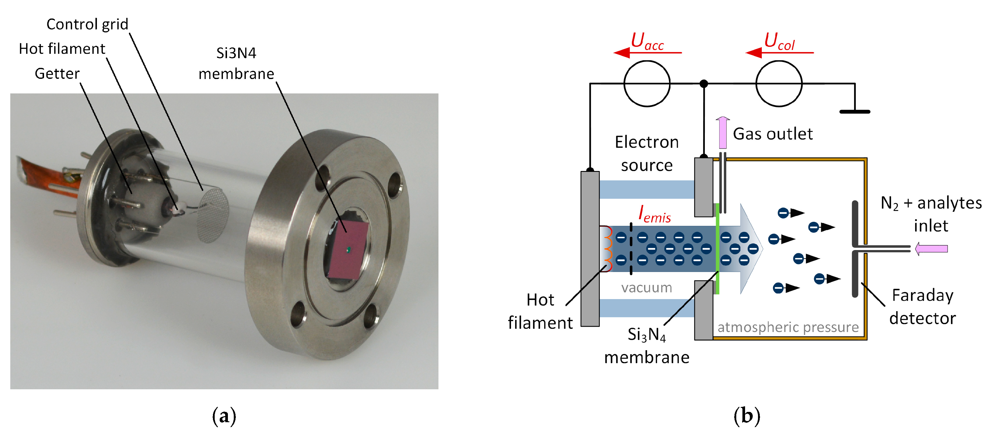
Our non-radioactive electron source, which is shown in
Figure 1a, is attached to a small ionization chamber manufactured from polyether ether ketone (PEEK) as shown in
Figure 1b. The electron source consists of a hot filament, a control grid and a getter and is sealed with a 300 nm thin silicon nitride (Si
3N
4) membrane. The membrane is 1.5 mm × 1.5 mm and transparent for electrons with sufficient electron energy [
5]. The generated free electrons are accelerated by applying an adjustable acceleration voltage
Uacc between the filament and the acceleration electrode and can partially transmit through the Si
3N
4 membrane to atmospheric pressure. By varying the acceleration voltage and filament heating current, the electron energy and density can be controlled.
Inside the ionization chamber a faraday plate detector is placed. By applying a constant collector voltage
Ucol (DC mode) between the acceleration electrode of the electron source and the Faraday detector, the generated electrons can be collected at the Faraday detector. This constitutes a constant detector current, which is amplified by our modified transimpedance amplifier [
6] with reduced gain and thus an increased input range and measured by a
Keysight 34461A multimeter. The carrier gas containing the analyte initially flows with a constant flow of 30 mls/min through the ionization chamber. Now, the electron-capturing compounds in the carrier gas can react with the free, thermalized electrons, leading to a decreased detector current [
7].
The carrier gas containing the analyte flows from the Faraday detector towards the electron source as depicted in
Figure 1b and described in our previous work [
4]. Furthermore, a constant acceleration voltage of
Uacc = 10 kV and an emission current of
Iemis = 40 nA is used. For generating a constant analyte vapor concentration, the analyte is filled into a permeation vial heated to 35 °C in a permeation oven purged with a constant flow of 600 mls/min of nitrogen. An adjustable fraction of this gas is diluted with pure nitrogen for generating different analyte concentrations in the carrier gas. For the following characterization, we used 1,1,2-trichloroethane (CAS: 79-00-5) and sevoflurane (CAS: 28523-86-6) as analyte, purchased from Sigma Aldrich (St. Louis, MI, USA).
3. Results and Discussion
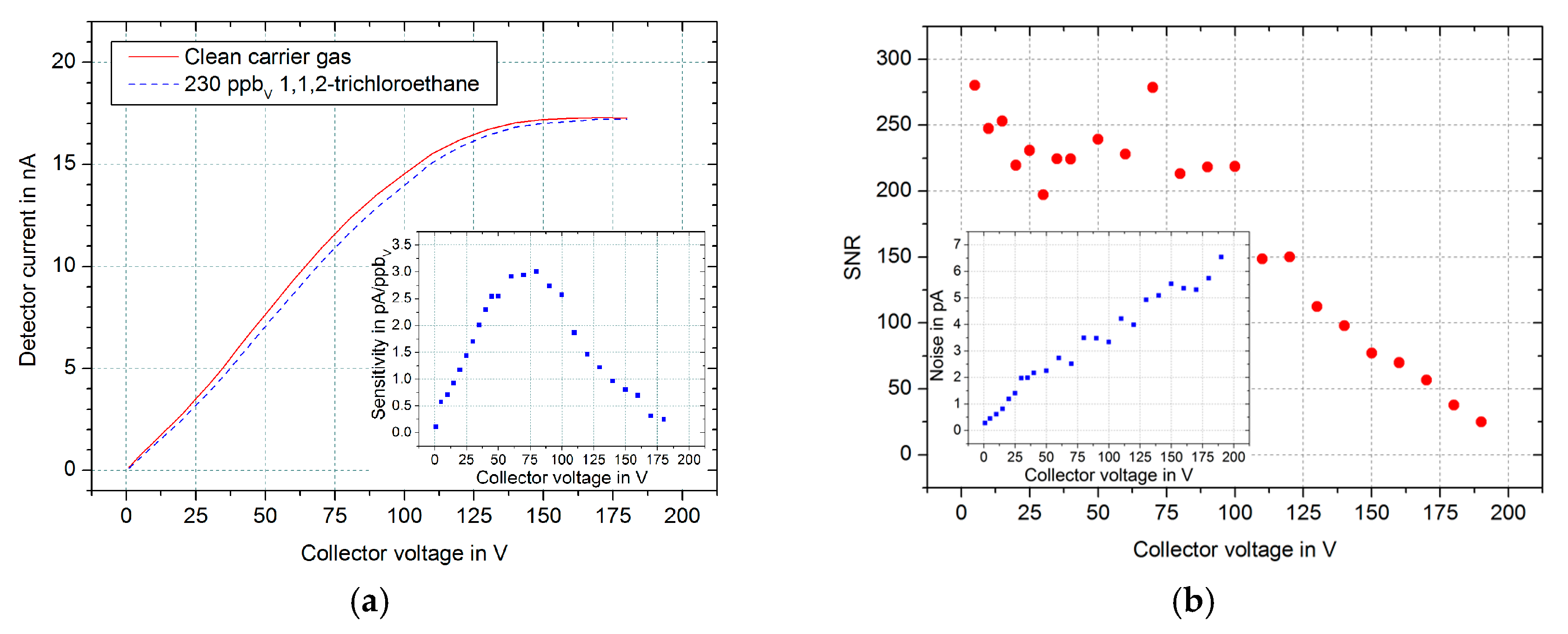
First, we investigated the influence of the collector voltage
Ucol on the achievable sensitivity of our setup. Therefore, the absolute detector current is measured for different collector voltages between
Ucol = 1 V and
Ucol = 180 V. For determining the respective sensitivities, the described collector voltage sweep is repeated, but with an 1,1,2-trichloroethane concentration of 230 ppb
v. The corresponding results are shown in
Figure 2a. The analyte reactions with the free electrons cause a decrease of the detector current. Thus, the difference between the two curves corresponds to the sensitivity of this setup, which is plotted in the inset in
Figure 2a. The detector currents for both curves saturate to the same value of
Idet,sat = 17.2 nA for higher collector voltages, independent of the analyte concentration. In addition, the sensitivity has a maximum value of
Smax = 2.9 pA/ppb
v at a collector voltage of
Ucol = 75 V.
However, not the sensitivity alone but rather a high signal-to-noise ratio (SNR) is important for a good limit of detection (LoD). Therefore, the SNR is calculated by dividing the sensitivity by the noise of the detector signal for a measuring time of 200 ms depending on the collector voltage. The results in
Figure 2b show that the noise (inset) increases linear with higher collector voltages. Thus, the SNR remains above a value of 200 up to
Ucol = 75 V, because the sensitivity increases also in this collector voltage range. For higher collector voltages, however, the SNR decreases significantly. Furthermore, for each repetition of these measurement the SNR has two maxima of 280 at
Ucol = 5 V and
Ucol = 75 V. Therefore, in the following measurements a collector voltage
Ucol = 5 V is used because of its significantly decreased instrumental effort.
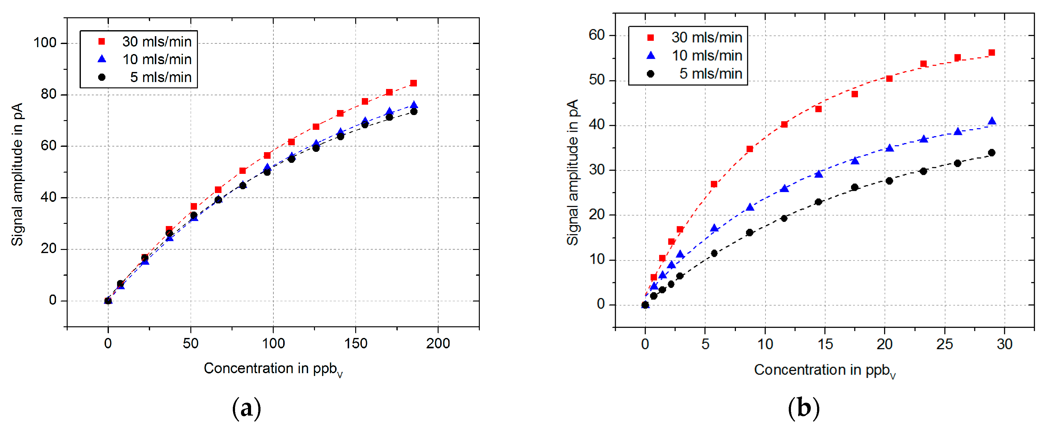
Now, the influence of the carrier gas flow on the resulting signal amplitude is investigated. Therefore, we performed measurements with 1,1,2-trichloroethane and sevoflurane at various concentrations for carrier gas flows of 5, 10 and 30 mls/min. The results in
Figure 3 show a slightly decreased sensitivity with lower carrier gas flows. A possible explanation for this can be that not all charged analyte molecules can be flushed out by the lower gas flows. Thus, not only the electrons but also the charged analyte molecules are detected, which reduce the signal amplitude. Furthermore, the typical non-linearity of the signal amplitude of electron capture detectors in DC mode [
8,
9] with increasing concentrations is recognizable.
Based on the measured linear signal increase of these measurements at low concentrations, we determined the limit of detection (LoD) for 1,1,2-trichloroethane and sevoflurane depending on the carrier gas flow. The LoD is defined as three times the standard deviation
σ of the measured noise. The calculated LoDs are listed in
Table 1 for a measuring time of 200 ms. These are comparable to the typical limit of detection using an ECD with the radioactive counterpart [
10].
4. Conclusions
In this work we present further investigations of the analytical performance of an electron capture detector equipped with our non-radioactive electron source based on the collector voltage and the carrier gas flow. The results show two maximum values of the SNR at collector voltages of Ucol = 5 V and Ucol = 75 V. Therefore, the lower voltage is preferred because of the reduced electronic requirements. Furthermore, we found that the limits of detection for 1,1,2-trichloroethane and sevoflurane is comparable to electron capture detectors with radioactive electron source, but slightly decrease with lower carrier gas flows. These limits could be improved by using a transimpedance amplifier with increased gain at the cost of a reduced input range, leading to an increased SNR.


