Proceeding Paper

Large Tilt Angle Lorentz Force Actuated Micro-Mirror with 3 DOF for Optical Applications †

Department of Electrical and Computer Engineering, University of Manitoba, Winnipeg, MB R3T 2N2, Canada
*
Author to whom correspondence should be addressed.
Presented at the Eurosensors 2017 Conference, Paris, France, 3–6 September 2017.
Proceedings 2017, 1(4), 351; https://doi.org/10.3390/proceedings1040351
Published: 8 August 2017
(This article belongs to the Proceedings of Proceedings of Eurosensors 2017, Paris, France, 3–6 September 2017)

Abstract

:
A versatile MEMS micro-mirror for optical platforms is presented, that operates using Lorentz force for actuation, resulting in low voltage operation. While maintaining below 20 mA drive current, this mirror has a tilting angle of over 50° and 20° around two diagonal axes and a linear motion of 1.5 mm in vertical axis. Compared to other works, it has larger angle of rotation and additional out of plane linear motion. The temperature rise on the mirror is kept bellow 25 °C to avoid thermal expansion of the support flexures and curvature of the mirror.

Published: 8 August 2017

1. Introduction

A matrix of micro-mirrors in which each mirror has two mechanical states is commercially called a Digital Micro-mirror Device (DMD). In DMDs, MEMS actuators are used to switch between the two mechanical states by tilting the mirror. DMDs were first introduced by Texas Instrument as the main optical component of the Digital Light Processors (DLPs) [1]. They are mainly used in micro projectors. In a DLP based micro projector, the binary map of an image is transferred to the DMD, while a white light coming from a light source shines on the DMD. The mirrors with on state reflect the light on the screen, while the other mirrors reflect the light away. The same mechanism was also used in 3D printers [2] to form the image on a UV sensitive photopolymer, and in 3D scanners instead of a moving slit to capture the hyperspectral image of the slices of a volume [3]. In the case of micro projectors, or generally the devices which are designed to work in two mechanical states with limited angle of tilting, electrostatic actuators have proved to be functional. They can provide a typical tilting angle of 10–12°. However, to get a tilting angle of larger than 10° by electrostatic actuations, a high input voltage is required. For example, reference [4] has applied 150 V for a tilt angle of ±18°. In addition, there are more applications for DMDs in which a large angle of tilting is needed. An example is catheter probes in which micro-mirrors are used to scan the surrounding tissue [5,6]. A larger angle of tilting, results in a larger scanning area. In many works, thermal actuators have been reported when a large displacement is required. They can successfully make a large motion but a high temperature rise on the device is needed, which might require a cooling system or limits to the applications of the micro-mirror. For example, the temperature on the flexures of catheter fabricated in reference [5] is 90 °C. Electromagnetic force has also been used for actuating micro-mirrors. Large stroke is possible, while consuming a low energy, making this type of actuator of interest for fabricating large-displacement devices [7]. For example, work done by reference [8] can tilt ±20°, while consuming 10 mW of power.
Depending on the application, micro-mirrors can tilt about one or multiple axes. In terms of mechanical structure, multi-axis micro-mirrors have been reported in two types of gimbaled and gimbal-less structures. Gimbaled structures are made of two frames. The inner frame includes the substrate of the mirror and can tilt about one longitudinal axis. It is connected to the outer frame through flexures. The outer frame is 90° rotated with respect to the inner frame and can tilt about its longitudinal axis which is perpendicular to the inner frame tilting axis [9,10,11,12]. These types of structures are usually of larger size compared to gimbal-less structures, and consume larger power in operation. In case of electromagnetic actuated gimbaled structures, since the direction of current in two frames are perpendicular to each other there is a limitation in aligning the magnetic field with the direction of current, in order to get the maximum force at each motion. In gimbal-less structures the springs are located at the corners or beneath the mirror substrate. Thermally actuated gimbal-less structures with large angle of tilting and flexibility were reported in [13] with ±25° tilt and 310 µm motion, and in [14] with ±40° tilt and 300 µm motion. However, they still suffer from high temperature rise on the springs and mirrors (more than 150 K in [13]).
In this paper, an optical platform is presented in which a fair trade-off between the operating factors is met. The gimbal-less electromagnetic actuated structure is designed to move in 3 dimensions while consuming a low power. It also provides individual control over the mirror sides. A large angle of tilt, more than 50° and 20°, in two diagonal axes and a linear motion of >1 mm in the vertical axis were achieved. The power consumption is 35 mW with a temperature rise of 25 °C.

2. Materials and Methods

Figure 1a shows the schematic of the structure. A permanent magnet is used to produce a strong uniform magnetic flux density of 0.4 T. A total of 4 flexures connect micro-mirror to the frame. Electric current passes through the wires on top of the flexures and mirror sides, so they undergo Lorentz force. Therefore, the motion is enabled by the force which is generated on the mirror sides and also the force which is transferred from springs to mirror at its corners. By reversing the direction of current, the direction of force will be changed, so each side of the micro-mirror can be pushed up or pulled down. Tilting and vertical axis motions can be achieved by controlling the direction of motion of each side.

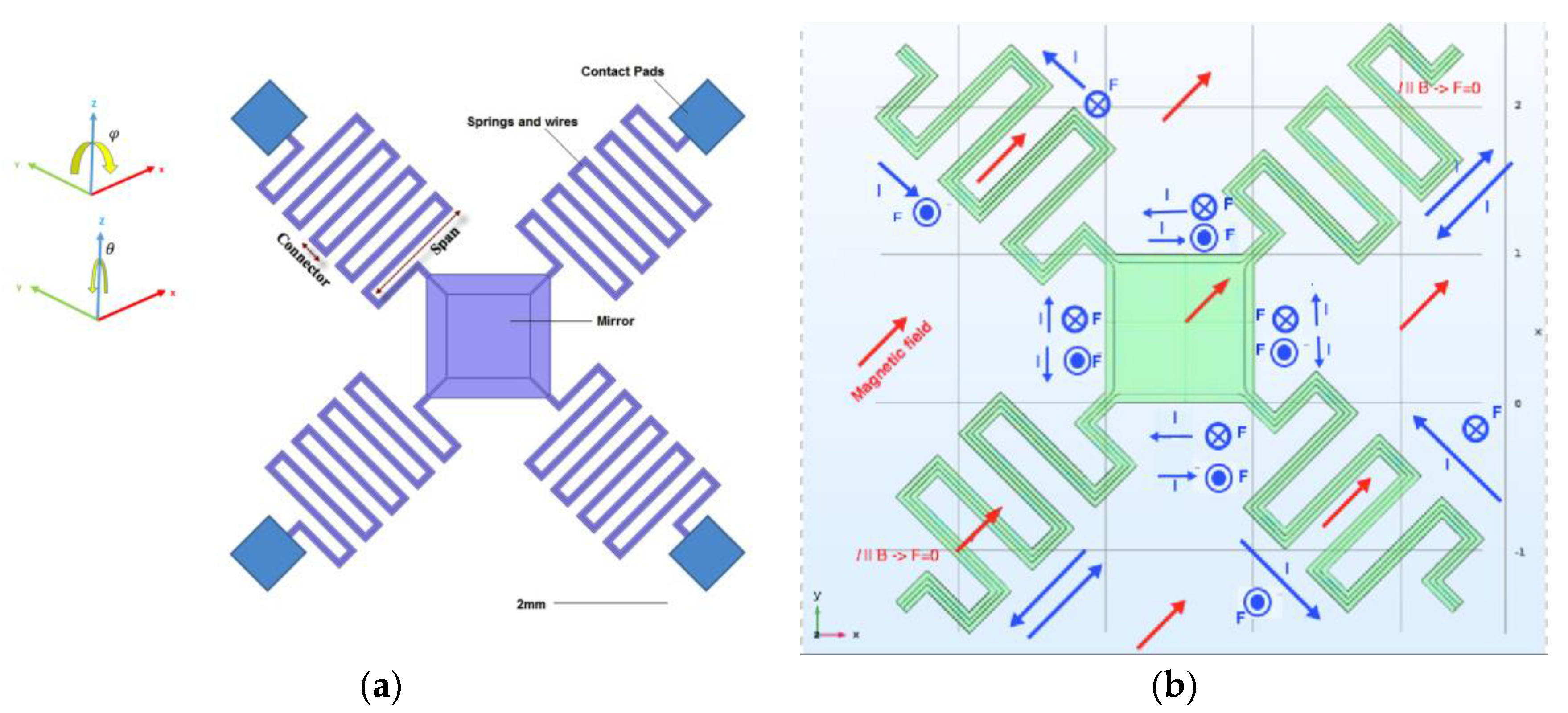
Mechanical Parameters Design
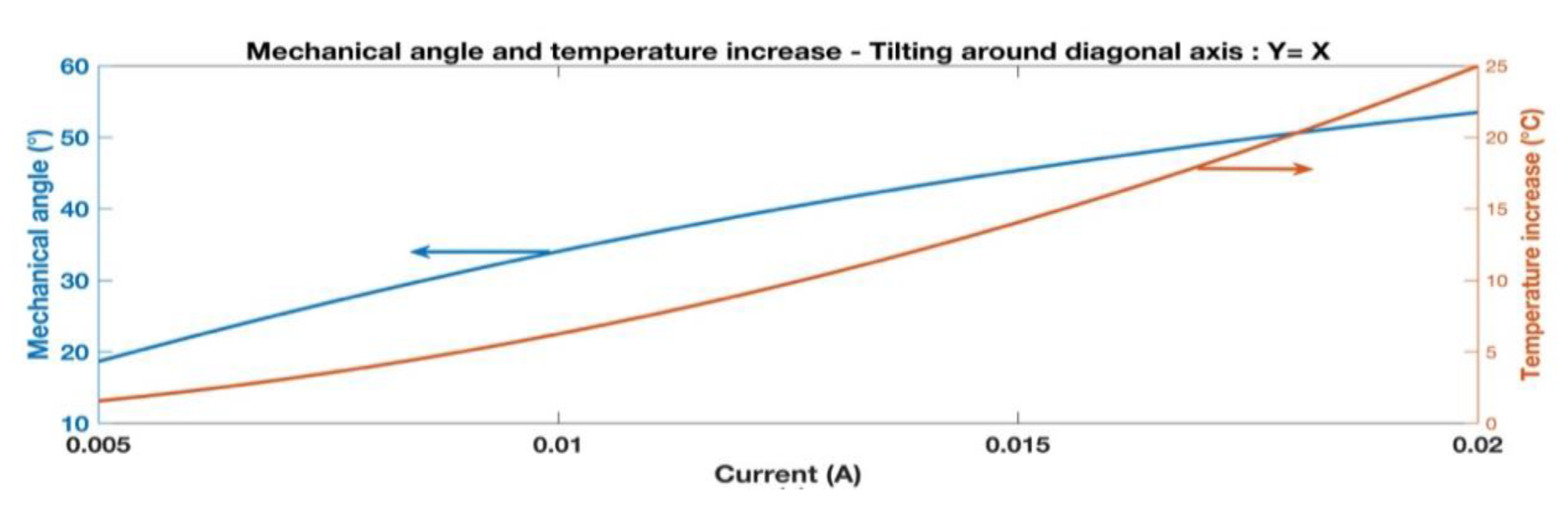
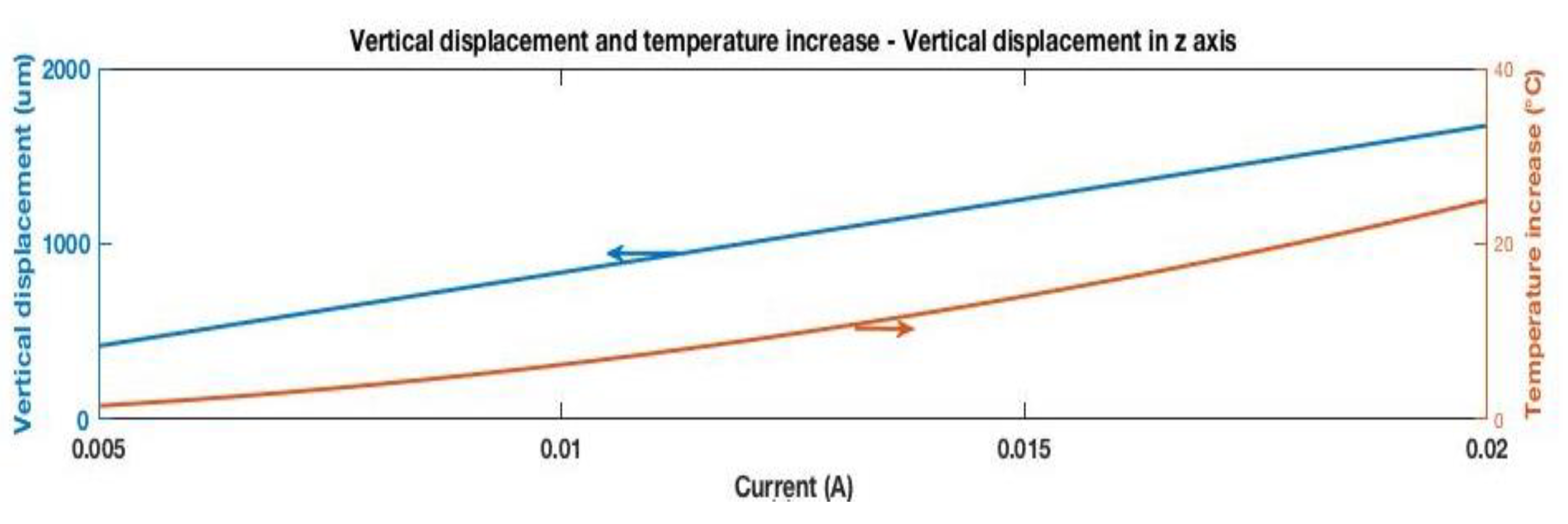
In a Lorentz force-actuated structure, the springs play two roles; electric conductor and mechanical support. As an electric conductor, the position of springs must be so that the direction of passing current be perpendicular to the direction of magnetic field. On the other hand, the springs must hold the mirror with minimum initial deformation or stress and have enough strength and flexibility for push up and pull down motions. One can conclude that spring is the most important part of a rotating micro-mirror. According to the Hooke’s law to increase the tilting angle of the mirror, a larger force with a smaller spring constant is needed. From the equation ( F Lorentz = I L × B ) it can be seen that by increasing the effective length of wires, the Lorentz force will be increased. To select the values based on a tradeoff between effective factors, finite element simulation was run. Based on the simulation results, the width of the wires was selected to be 35 μm, and the thickness 1.5 μm. The length of the spans and connectors shown in Figure 1a, were selected to be 2 mm and 200 μm. The substrate material should be of low young’s modulus to enable large motion, so a thin 10 μm layer of SU-8 polymer was used as substrate material for membrane and flexures. The wires and mirror were made out of aluminum which has a high visible reflectivity and appropriate electrical conductivity. The effect of magnetic field on the wires passing through flexures and mirror sides is shown in Figure 1b. The magnetic field is 45° angled with respect to the mirror sides. By this configuration, Lorentz force exerts on all sides of the mirror and two springs which are perpendicular to it.

3. Results

The finite element simulation was done by applying current in the range of 5 mA to 20 mA. At each step a fixed current was applied to the contact pads shown in Figure 1a. The total electric power consumption is calculated to be 34.88 mW, which results in a temperature increase of 25 °C on wires. This temperature is tolerable for the structure and the heat will be distributed in the substrate. Figure 2 shows the variation of mechanical angle vs applied current. A maximum of 53° mechanical angle could be achieved by applying 20 mA for tilting around the ϕ axis. This value is about 23° for tilting around the diagonal θ axis. Since the flexures on the y = x vector are parallel to the magnetic field, no Lorentz force is applied to them. Therefore, the amount of tilt around the θ axis is lower than the amount of tilt around the ϕ axis. Figure 3, shows the vertical axis along z axis. The amount of displacement by applying 20 mA is 1500 µm. In this motion, all four sides of mirror are actuated. According to the simulations, the linearity of movement across the sides of the mirror is 93%, which means that in a vertical motion, the difference between the displacements of two adjacent corners is not more than 7% of the maximum displacement.

4. Conclusions

An electromagnetically actuated scanning micro-mirror has been designed and simulated. The structure is able to tilt around 2 diagonal axes in x-y plane and move vertically in the z axis. The structure was simulated in a finite element software (COMSOL) and the operating principles were discussed. A mechanical angle of 53° and 23° was shown to be achievable in x and y axes respectively. The main contributions of this study include designing a large multi-axis motion actuator with individual control over each side while consuming a low electrical power.

Acknowledgments

Authors would like to acknowledge Natural Sciences and Engineering Research Council (NSERC) of Canada, and the University of Manitoba Graduate Fellowship (UMGF) for their financial support.

Conflicts of Interest

The authors declare no conflict of interest. The founding sponsors had no role in the design of the study; in the collection, analyses, or interpretation of data; in the writing of the manuscript, and in the decision to publish the results.

References

  1. Dudley, D.; Duncan, W.; Slaughter, J. Emerging digital micromirror device (DMD) applications. In Proceedings of the MOEMS Display and Imaging Systems, San Jose, CA, USA, 20 January 2003; Volume 4985. [Google Scholar] [CrossRef]
  2. Lee, M.P.; Cooper, G.J.; Hinkley, T.; Gibson, G.M.; Padgett, M.J.; Cronin, L. Development of a 3D printer using scanning projection stereolithography. Sci. Rep. 2015, 9875. [Google Scholar] [CrossRef] [PubMed]
  3. Arablouei, R.; Goan, E.; Gensemer, S.; Kusy, B. Fast and robust pushbroom hyperspectral imaging via DMD-based scanning. In Proceedings of the Novel Optical Systems Design and Optimization XIX, San Diego, CA, USA, 28 August 2016; Volume 9948, p. 99480. [Google Scholar] [CrossRef]
  4. Kawajiri, Y.; Nemoto, N.; Yamamoto, T.; Yamaguchi, J.; Makihara, M.; Ishii, Y.; Sasakura, K.; Shimokawa, F. 512 × 512 port 3D MEMS optical switch module with toroidal concave mirror. NTT Tech. Rev. 2012, 10, 1–6. [Google Scholar]
  5. Xu, Y.; Singh, J.; Jason, T.H.; Ramakrishna, K.; Premchandran, C.S.; Kelvin, C.W.; Kuan, C.T.; Chen, N.; Olivo, M.C.; Sheppard, C.J. MEMS based non-rotatory circumferential scanning optical probe for endoscopic optical coherence tomography. In Proceedings of the European Conference on Biomedical Optics, Munich, Germany, 17 June 2007. [Google Scholar] [CrossRef]
  6. Aguirre, A.D.; Herz, P.R.; Chen, Y.; Fujimoto, J.G.; Piyawattanametha, W.; Fan, L.; Wu, M.C. Two-axis MEMS scanning catheter for ultrahigh resolution three-dimensional and en face imaging. Opt. Exp. 2007, 15, 2445–2453. [Google Scholar] [CrossRef] [PubMed]
  7. Park, B.; Afsharipour, E.; Chrusch, D.; Shafai, C.; Andersen, D.; Burley, G. Large Displacement Bi-Directional Out-of-Plane Lorentz Actuator Array for Surface Manipulation. J. Micromech. Microeng. 2017. [Google Scholar] [CrossRef]
  8. Raboud, D.; Barras, T.; Conte, F.L.; Fabre, L.; Kilcher, L.; Kechana, F.; Abelé, N.; Kayal, M. MEMS based color-VGA micro-projector system. In Proceedings of the Eurosensors XXIV, Linz, Austria, 5–8 September 2010. [Google Scholar] [CrossRef]
  9. Cho, A.R.; Han, A.; Ju, S.; Jeong, H.; Park, J.H.; Kim, I.; Bu, J.U.; Ji, C.H. Electromagnetic biaxial microscanner with mechanical amplification at resonance. Opt. Exp. 2015, 23, 16792–16802. [Google Scholar] [CrossRef] [PubMed]
  10. Baran, U.; Brown, D.; Holmstrom, S.; Balma, D.; Davis, W.O.; Muralt, P.; Urey, H. Resonant PZT MEMS scanner for high-resolution displays. J. Microelectromech. Syst. 2012, 21, 1303–1310. [Google Scholar] [CrossRef]
  11. Hung, A.C.; Lai, H.Y.; Lin, T.W.; Fu, S.G.; Lu, M.S. An electrostatically driven 2D micro-scanning mirror with capacitive sensing for projection display. Sens. Actuators A. Phys. 2015, 222, 122–129. [Google Scholar] [CrossRef]
  12. Cho, I.J.; Yoon, E. A low-voltage three-axis electromagnetically actuated micromirror for fine alignment among optical devices. J. Micromech. Microeng. 2009, 19, 085007. [Google Scholar] [CrossRef]
  13. Jia, K.; Samuelson, S.R.; Xie, H. High-Fill-Factor Micromirror array with hidden bimorph actuators and tip–tilt-piston capability. J. Microelectromech. Syst. 2011, 20, 573–582. [Google Scholar] [CrossRef]
  14. Morrison, J.; Imboden, M.; Little, T.D.; Bishop, D.J. Electrothermally actuated tip-tilt-piston micromirror with integrated varifocal capability. Opt. Exp. 2015, 23, 9555–9566. [Google Scholar] [CrossRef] [PubMed]
Figure 1. (a) Schematic of the actuator; ϕ and θ show the direction of rotation; (b) Red arrows show the magnetic field; blue arrows show direction of current; and circular signs show direction of force.
Proceedings 01 00351 g001
Figure 2. Results of simulated micro-mirror when tilting around diagonal axis of ϕ (y = x).
Proceedings 01 00351 g002
Figure 3. Results of simulated micro-mirror when vertically moving up in z axis.
Proceedings 01 00351 g003
Publisher’s Note: MDPI stays neutral with regard to jurisdictional claims in published maps and institutional affiliations.

