Proceeding Paper

Piezoresistive Pressure Sensors for Resin Flow Monitoring in Carbon Fibre-Reinforced Composite †

1
Friedrich-Wilhelm-Bessel-Institut Forschungsges. m.b.H., Bremen, Germany
2
Faserinstitut Bremen, e.V. FIBRE, Bremen, Germany
3
Institute for Micro-Sensors, -Actuators and -Systems (IMSAS), Bremen, Germany
*
Author to whom correspondence should be addressed.
Presented at the Eurosensors 2017 Conference, Paris, France, 3–6 September 2017.
Proceedings 2017, 1(4), 339; https://doi.org/10.3390/proceedings1040339
Published: 18 August 2017
(This article belongs to the Proceedings of Proceedings of Eurosensors 2017, Paris, France, 3–6 September 2017)

Abstract

:
Using piezoresistive pressure sensors and in-situ measurement of pressure gradient, the infusion of resin in fiber reinforced composite can be optimized. The optimization of resin flow in Vacuum Assisted Resin Infusion (VARI) is necessary to produce high-quality fibre-reinforced composites. To control the resin infusion process, piezoresistive pressure sensors are embedded to detect the resin flow and resin pressure in Carbon Fibre Reinforced Polymer (CFRP). The measured pressure validates the accuracy of analytical calculations, based on Darcy’s law in a porous medium. The sensors are of small size and therefore do not affect the natural flow of the resin.

1. Introduction

In Vacuum Assisted Resin Infusion (VARI) processes, low viscosity resin will fill up dry stacking of glass or carbon fabrics. There is a pressure difference between the resin inlet and vacuum port. This difference of pressure is the leading force for the resin to fill the dry fabrics. Mainly, trial and error processes are used to foresee the resin flow in laminates, which are costly and unreliable. To reduce the cost and increase the quality, in-situ measurements using cameras [1], ultrasonic transducers [2], optical fibres [3] and pressure sensors [4] are done. Since resin infiltrates the fabric by pressure gradients between the resin inlet and outlet, the most relevant measurement to detect the resin flow and the resin pressure simultaneously can be done by means of pressure sensors [4]. In this paper, the piezoresistive pressure sensors are wire bonded on Kapton PCBs and the changes of resin pressure during infusion is monitored in CFRP. The area of PCB reduced from 58 cm2 in [4] to 4 cm2 in this paper. It is important to minimize the size of the embedded sensing element to reduce the wound effect [5] caused by integrating a foreign body in the host material.

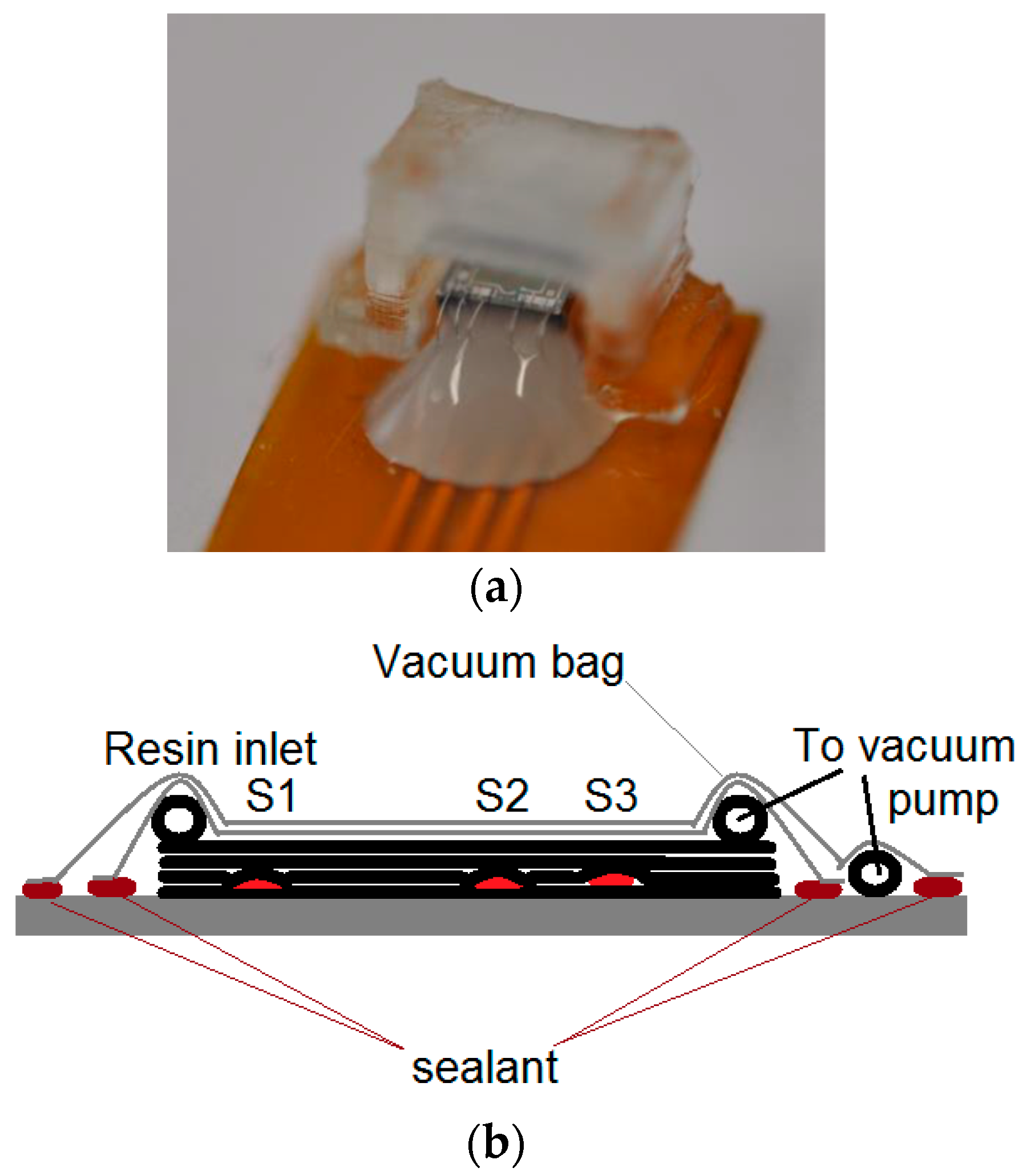
2. Materials and Methods

Three piezoresistive pressure sensors are wire bonded to the Kapton PCB, using aluminum wires and the wedge-wedge bonding method. The bonded wires are protected by GE680 (Kationbond, UV-curing encapsulant, www.delo.de). The sensors are placed inside a laminate of carbon fabrics, which is sealed by a vacuum bag. An inlet for the resin and an outlet to the vacuum pump is preserved to/from the airtight laminate. When the vacuum is applied, the fabric inside the vacuum bag is compacted. This compaction will deflect the sensor membrane. To prevent this deflection due to vacuum, a protection cap is glued on top of each sensor. These protection caps are 3D printed (Clear resin type 1 from FormLabs). Figure 1a shows a photograph of the sensor with the applied protection cap.
Three piezoresistive pressure sensors are embedded on the bottom ply of the 4-layer carbon fabrics laminate. The stacking of fibers and sensors are schematically shown in Figure 1b. The sensors are placed with a distance of 2.8, 13.0 and 31.0 cm from the infusion line. Spiral tubes are used to provide linear resin infusion and vacuum suction. The laminate is sealed and evacuated by a vacuum pump. The resin RIM 035c is mixed with hardener RIMH 037 (Hexion) and infused at room temperature. Since the mixture has a sufficient low viscosity, no further heating is required to reduce the viscosity prior to infusion.
Darcy’s law of fluid flow in porous media [6] is initially used to study the resin flow. This law is extended and used to study the flow of resin in Vacuum Assisted Rein Infusion (VARI) composite production processes.
ν = K η   p
where ν is the volume average velocity, K is the permeability tensor, η is the resin viscosity, and p is the resin pressure.
Since the resin is an incompressible fluid, the continuity equation is valid for that
ν = 0 .
Inserting Equation (1) in continuity Equation (2) results in
( K η   p ) = 0 .

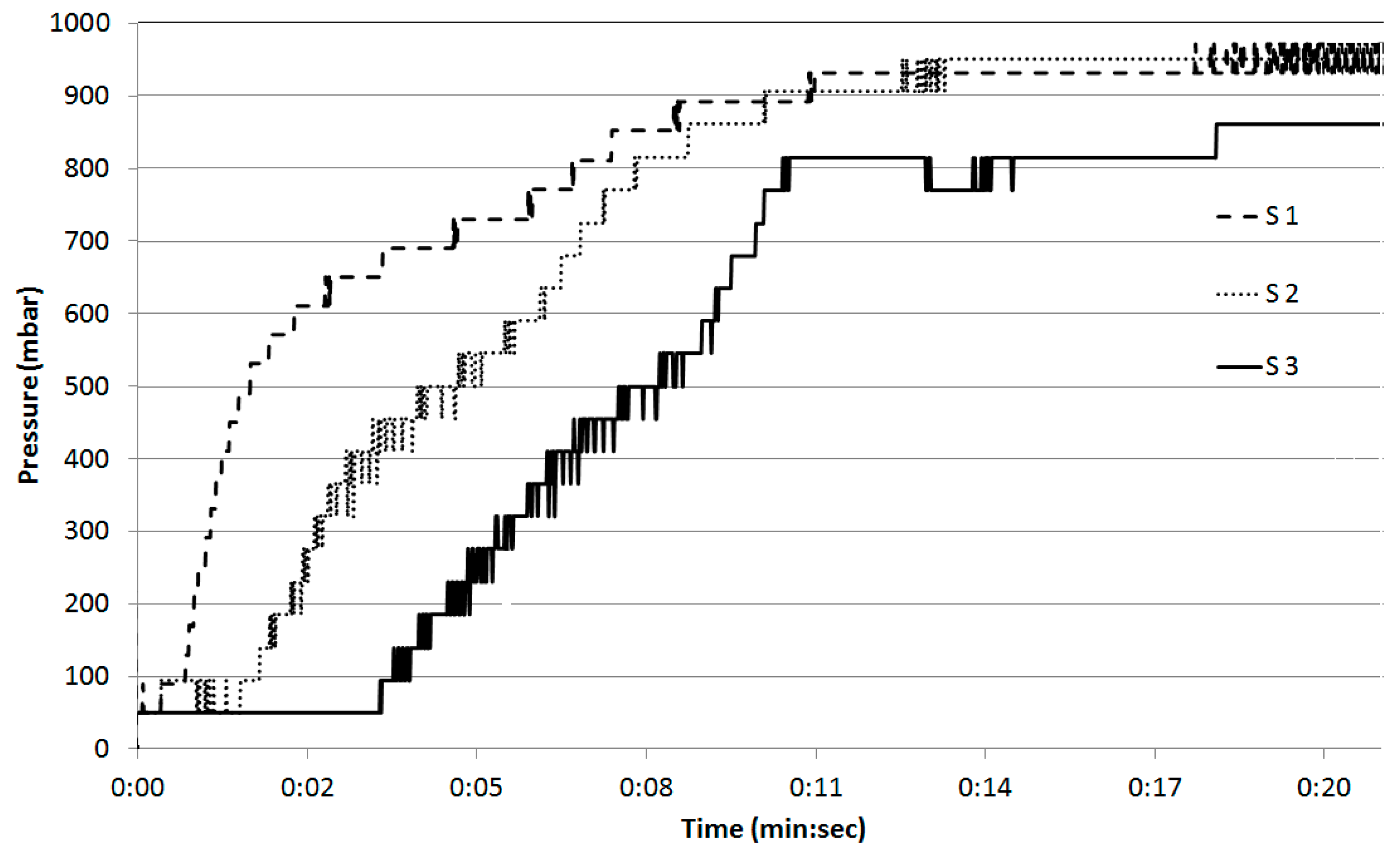
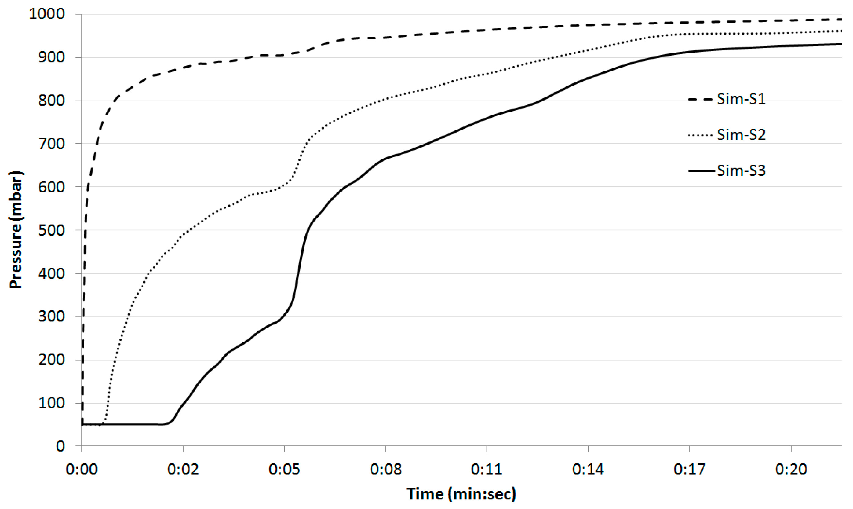
3. Results and Discussion

The resin reservoir is placed at atmospheric pressure. When the resin is infused into the laminate, pressure elevates gradually at the point impregnated by the resin. The sensor close to the resin infusion point shows faster changes in pressure than others. Figure 2 demonstrates the measured pressure inside the laminate during the resin infusion. When the resin reaches any of the embedded sensors, that sensor measures a sudden increase in pressure. The closer the sensor is to the infusion line (S1), the steeper the increase of pressure. The closer the sensor to the vacuum port is (S3) the slower the increase of pressure.
The measured pressure can be used to validate the analytical calculation based on Darcy’s law. Each sensor is calibrated between 5 mbar and atmospheric pressure prior to embedding. In this study an Arduino card is used for measurement. Wire bonded piezoresistive pressure sensors on flexible PCBs have a small footprint. The pressure sensors are embedded in carbon fibre reinforced polymer. The sensors are successfully measuring the pressure changes in VARI process during resin infusion.
In this paper, the analytical calculation of the pressure gradient inside the laminate based on Darcy’s law is done using RTM-Worx software. The calculated pressure is given in Figure 3.
Comparison between the measured and calculated pressure based on Darcy’s law shows that two graphs fit each other. A better A/D converter will provide a better measurement resolution.

Conflicts of Interest

The authors declare no conflict of interest.

References

  1. Loendersloot, R. The Structure-Permeability Relation of Textile Reinforcements. Ph.D. Thesis, Engineering Technology (CTW), University of Twente, Enschede, The Netherlands, 2006. Available online: http://doc.utwente.nl/55931/ (accessed on 9 June 2017).
  2. Konstantopolous, S.; Fauster, E.; Schledjewski, R. Monitoring the production of FRP composites: A review of in-line sensing methods. Express Polym. Lett. 2014, 8, 823–840. [Google Scholar] [CrossRef]
  3. Gupta, N.; Sundaram, R. Fiber optic sensors for monitoring flow in vacuum enhanced resin infusion technology process. Compos. A Appl. Sci. Manuf. 2009, 40, 1065–1070. [Google Scholar] [CrossRef]
  4. Kahali Moghaddam, M.; Breede, A.; Brauner, C.; Lang, W. Embedding piezoresistive pressure sensors to obtain online pressure profiles Inside fiber composite laminates. Sensors 2015, 15, 7499–7511. [Google Scholar] [CrossRef] [PubMed]
  5. Lang, W.; Boll, D.; Tolstosheeva, E.; Ibragimov, A.; Schubert, K.; Brauner, C.; Pille, C. Embedding without disruption: The Basic Challenge of Sensor Integration. In Proceedings of the 2012 IEEE SENSORS, Taipei, Taiwan, 28–31 October 2012. [Google Scholar]
  6. Darcy, H.P.G. Les Fontaines Publiques de la Ville de Dijon; Dalmont: Paris, France, 1856. [Google Scholar]
Figure 1. (a) A piezoresistive pressure sensor wire bonded on a Kapton PCB; (b) A schematic of 3 piezo resistive pressure sensors on bottom layer of 4 plies laminate.
Proceedings 01 00339 g001
Figure 2. Measured pressure during resin infusion by pressure sensors. The laminate is filled up with the resin in 21 min.
Proceedings 01 00339 g002
Figure 3. Analytical calculation of pressure inside the CFRP laminate based on Darcy’s law using RTM-worx software.
Proceedings 01 00339 g003
Publisher’s Note: MDPI stays neutral with regard to jurisdictional claims in published maps and institutional affiliations.

