Abstract
A new three-axis magnetometer for both 3-D magnetic field sensing and contactless in-plane 360° absolute angle encoding has been developed. The magnetometer is based on the Hall effect and consists of a circular in-plane sensitive CMOS Hall-effect microsensor, biasing and signal conditioning circuits. The sensing device contains a narrow n-well ring with a chain of contacts positioned radial on the ring. The signal conditioning circuit gives two output analogue signals: a voltage Vz, proportional to the magnetic field component Bz, and a sine wave function Vxy(t). The magnitude of the in-plane magnetic field B(x,y) is directly proportional to the sine amplitude and the phase Ψ corresponds to the angle between the applied in-plane magnetic field and a reference direction.
1. Introduction
Magnetic sensors for contactless angular position measurement and/or multidimensional magnetic field sensing are widely used in automation, robotics, mechatronics, industrial controls, navigation etc. Many different versions of 2D and 3D Hall microsensors are available for this purpose. Some of them [1,2,3,4] use measurement principles based on complex trigonometric calculation algorithm for angle evaluation. As a result, the angle extraction circuit is very complicated. This circumstance, as well as the stronger requirements for precise matching of the characteristics of the corresponding sensor channels increases fabrication cost. A circular 2D CMOS integrated magnetometer based on 8-contact circular parallel-field Hall device is presented in [3]. Due to the very small number of ring periphery contacts (8 only) and the five-contact parallel-field Hall sensor used, the magnetic sensitivity S of such magnetometer is relatively low: for example, it is about 30% lower compared to five-contact Hall transducers. Another circular 2D CMOS Hall magnetometer consisting of a narrow n-well ring with a chain of 64 ohmic contacts spaced at regular intervals along the ring circumference is presented, too [4]. The great number of the device’s contacts (64) imposes the following limitations: technological restrictions, large diameter of the ring (hence lower resolution), low measurement rate, and complicated interface electronics. In [5], two-axis CMOS Hall-effect device is presented which overcomes some of the shortcomings of the discussed above solutions, mainly due to the advantages of using a three-contact parallel-field Hall microdevice instead of five-contact sensor segments. Its sensing unit comprise a circular parallel-field CMOS Hall-effect microsensor, containing a narrow n-well ring with a chain of 32 contacts spaced at regular intervals along the ring’s circumference. However, this device is not capable to sense the third component of the magnetic field, which is perpendicular to the n-ing plane.
In this paper, a three-axis magnetometer for both 3D magnetic field sensing and contactless in-plane 360° absolute angle encoding is presented.
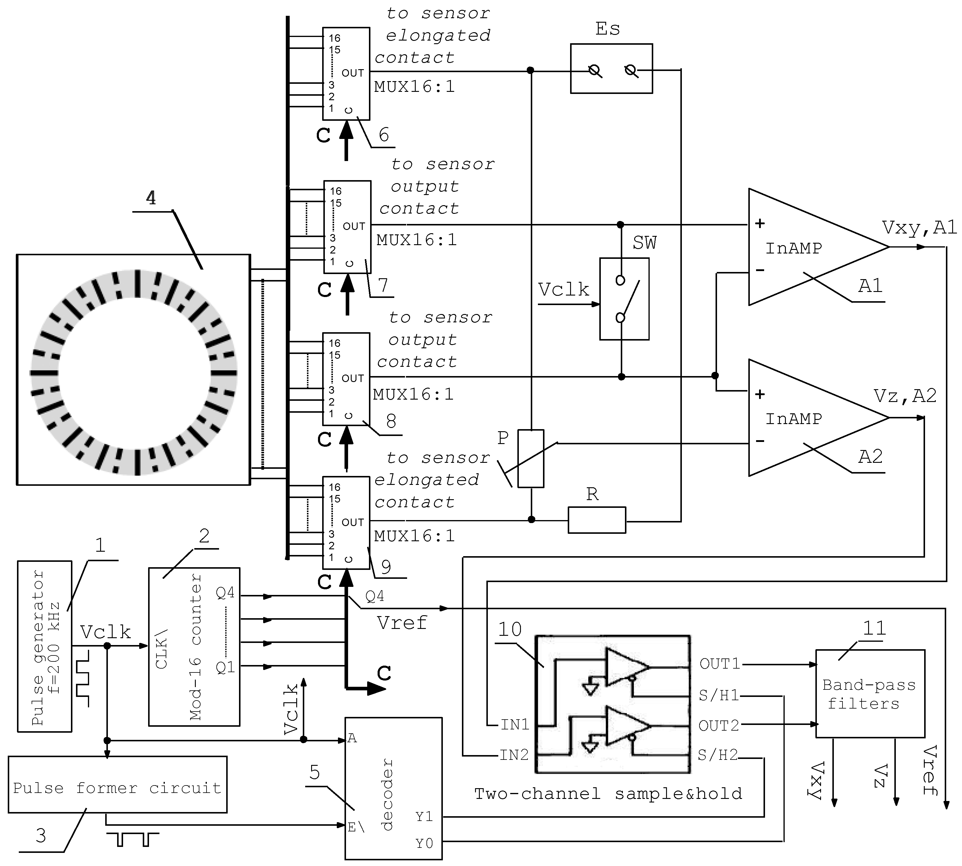
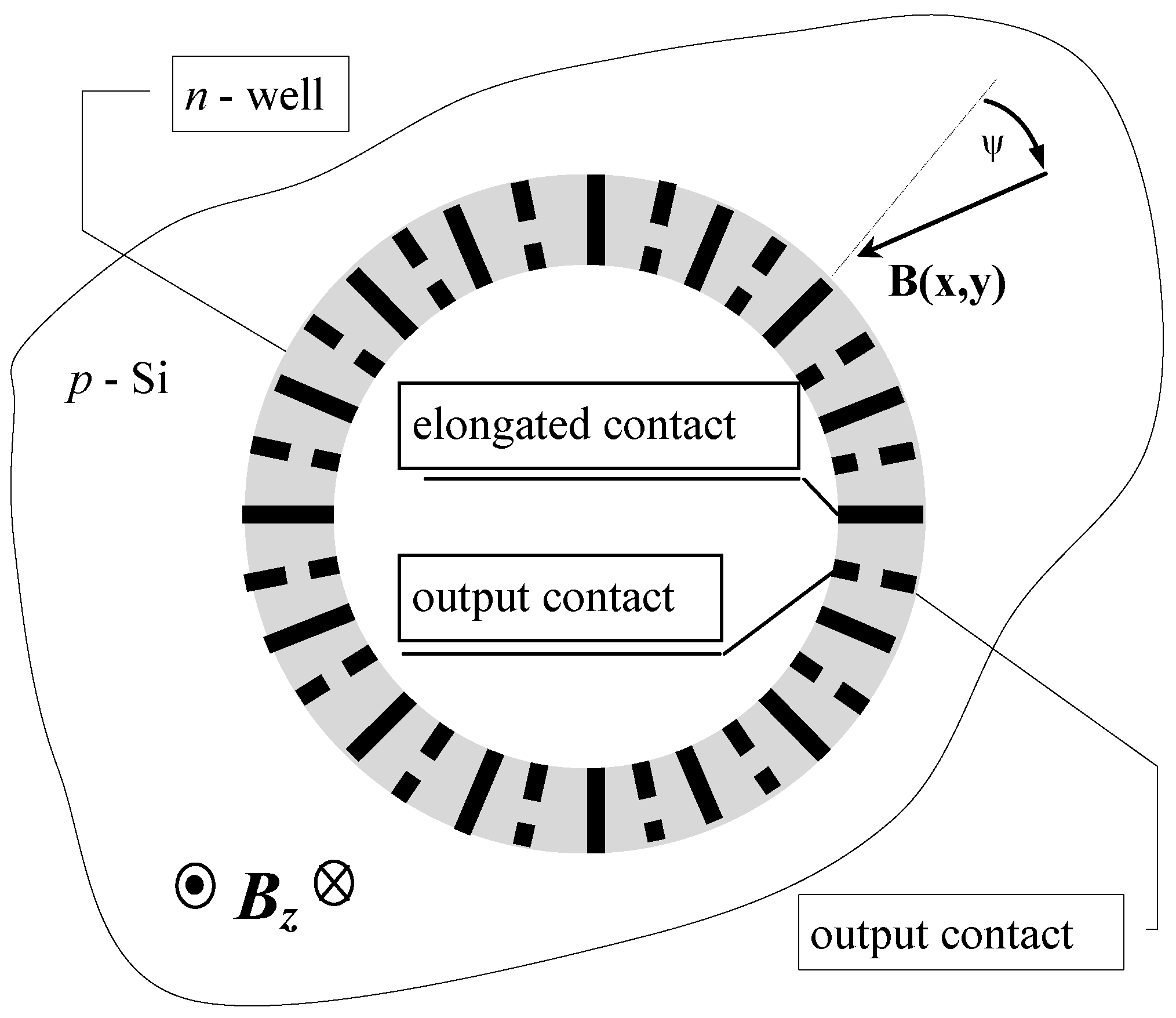
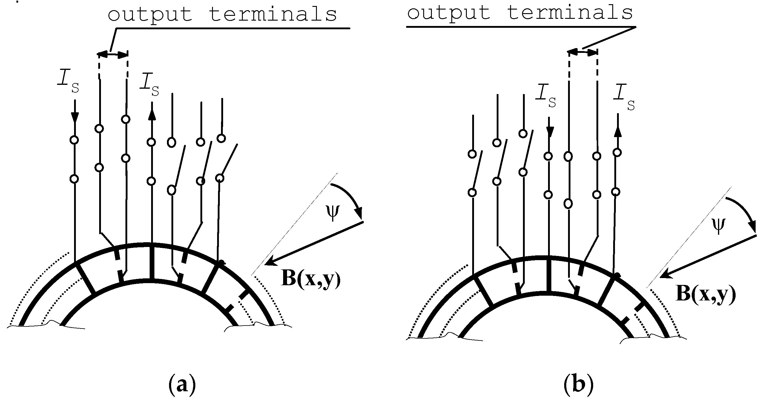
2. Realization and Working Principle of the Magnitometer
The sensing device of the magnetometer is based on a single four-contact 2D silicon Hall microsensor, which is described in [6] together with its operation principle. This new microsensor contains a narrow n-well ring with a chain of contacts positioned radial on the ring as follows: 16 oblong contacts are spaced at regular intervals along the ring’s circumference; between each pair of adjacent oblong contacts, a pair of short output contacts is positioned. Both short output contacts from a corresponding pair are positioned on the same radius—one contact close to the inner side of the ring, and other contact close to its outer side, Figure 1.
Figure 1.
The new circular Hall 3D magnetometer based on a four-contact Hall microsensor using conventional CMOS technology.
Each contact is either active, i.e., connected to the bias and/or to the readout interface, or passive, i.e., disconnected. Under operation, only one segment including pair of adjacent oblong contacts together with the pair of short output contacts between them is active at a time, as shown in Figure 2.
Figure 2.
Circular Hall microdevice based on an original four-contact 2D Hall microsensor: (a) the active neighbouring contacts in position n; (b) the active contacts in position n + 1.
This segment forms a four-contact 2-D Hall microsensor [6]. By means of four multiplexers, this sensor segment can virtually move along the ring. The motion step is equal to one oblong contact.
The block diagram of the magnitometer is shown in Figure 3.
Figure 3.
Block diagram of the magnetometer.
The activated two adjacent oblong contacts are connected to the power supply Vs through the high-ohmic resistor R and through the multiplexers 6 and 9, Figure 3. Also, these oblong contacts are connected to the high-ohmic potentiometer P. As is described above, the pair of short output contacts between the activated two adjacent oblong contacts is also activated at the same time. These output contacts are connected to the input terminals of the instrumentation amplifier A1 through the multiplexers 7 and 8, Figure 3. Also, these contacts are connected to SPST analog switch SW, Figure 3. To measure the parallel to the ring plane magnetic field B(x,y), i.e., “in-plane” magnetic field, the switch SW closed, and this way the activated ring output contacts are linked together. The differential output for the B(x,y), is the middle point of the potentiometer P and linked together activated ring output contacts, where voltage V(x,y), proportional to B(x,y), may be measured. This voltage is passed to the input terminals of the instrumentation amplifier A2. The A2 output provide amplified voltage Vxy,A2 proportional to B(x,y). Due to the virtual motion of the active sensor contacts, i.e., the active sensor region, in the presence of in-plane magnetic field B(x,y), the output signal Vxy,A2 (respectively V(x,y)) is modulated. The modulation period is determined by the time needed for the segment to make one turn of 360°. Therefore, the output voltage Vxy,A2 (respectively V(x,y)) is sine functions of time that carries information about the magnetic field amplitude and direction like the transducer described in [5]. To measure the normal to the ring plane magnetic field component B(z), the switch SW opened. Thus, the differential output for B(z) are the short output contacts themselves, where voltage V(z), proportional to B(z), may be measured. This voltage is passed to the input terminals of the instrumentation amplifier A1. The A1 output provide amplified voltage Vz,A2 proportional to B(z). The outputs of Block 12 (band-pass filters) gave stable, amplified and noise-free voltages Vxy and Vz, shown in Figure 4, proportional to in-plane magnetic field B(x,y) and magnetic field component B(z) respectively. The reference signal Vref, generated from Block 2, is used to measure the angle Ψ, as is shown in Figure 4.
Figure 4.
The output voltage of the device when constant magnetic field B is applied.
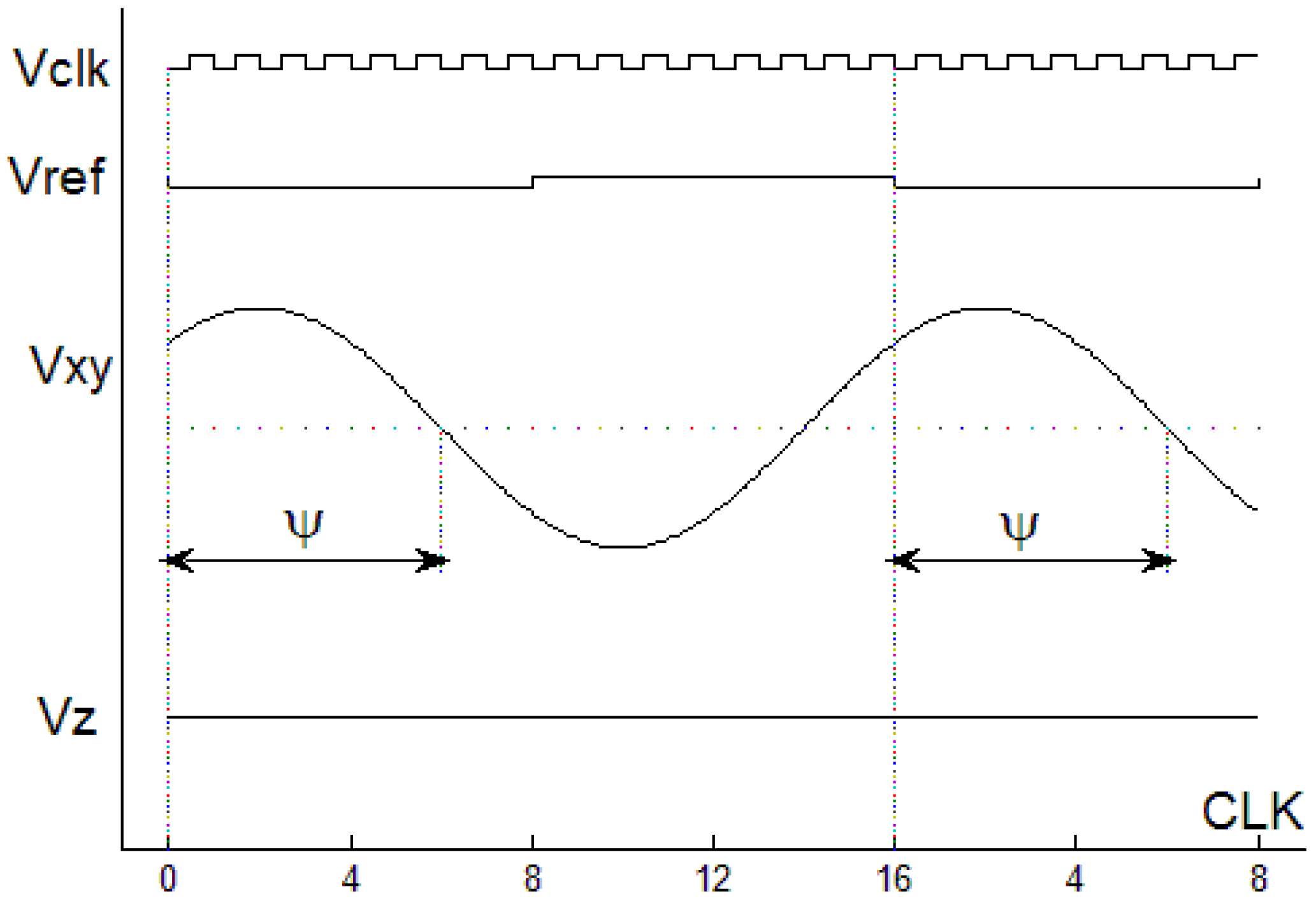
3. Experimental Results and Conclusions
Figure 4 illustrates the output voltage when the microdevice is exposed to constant magnetic field B(Bx, By, Bz). The overall magnetic induction measurement error for both in-plane magnetic field B(x,y) and magnetic field component B(z) in the range −1.0 T ≤ B ≤ 1 T is no more than 1.0%. The overall absolute angle Ψ measurement error is no more than 0.5°. At a supply current Is = 0.5 mA and a 10 Hz bandwidth the 1/f noise level of the new circular Hall device is about 40 times low in comparison the discrete four-contact parallel-field Hall microsensor. The sensitivity of this unique circular transducer is about 51 V/AT.
The performance achieved is promising to variety of contactless angular position measurement and/or multidimensional magnetic field sensing applications.
Acknowledgments
This work was supported by Sci. Res. Fund at MES under project No. DN 07/18-15.12.2016.
Conflicts of Interest
The authors declare no conflict of interest.
References
- Paranjape, M.; Ristic, L.; Allegretto, W. Simulation, design and fabrication of a vertical Hall device for two-dimensional magnetic field sensing. Sens. Mater. 1993, 42, 91–101. [Google Scholar]
- Roumenin, C. Microsensors for magnetic field (Chapter 9). In MEMS—A Practical Guide to Design, Analysis and Applications; Korvink, J., Paul, O., Eds.; William Andrew Publishing: Norwich, NY, USA, 2006; pp. 453–523. ISBN 0-8155-1497-2. [Google Scholar]
- Banjevic, M.; Furrer, B.; Popovic, R. 2D CMOS integrated magnetometer based on the miniaturized circular vertical hall device. In Proceedings of the Transducers 2009, Denver, CO, USA, 21–25 June 2009; pp. 877–880. [Google Scholar]
- Kejik, P.; Reymond, S.; Popovic, R. Circular Hall transducer for angular position sensing. In Proceedings of the Transducers ′07 & Eurosensors XXI: The 14th International Conference on Solid-State Sensors, Actuators, and Microsystems, Cité I Centre des Congrès, Lyon, France, 10–14 June 2007; Digest of Technical Paper. Volume 2, pp. 2593–2596. [Google Scholar]
- Noykov, S.; Lozanova, S.; Roumenin, C. Two-axis magnetometer using a circular parallel-field Hall microsensor for contactless angle measurement. Electron. Lett. 2010, 46, 1130–1132. [Google Scholar] [CrossRef]
- Lozanova, S.; Noykov, S.; Roumenin, C. 2-D semiconductor magnitometer. Regist. Bulg. Pat. Appl. N 112109/07.10.2015.
© 2017 by the authors. Licensee MDPI, Basel, Switzerland. This article is an open access article distributed under the terms and conditions of the Creative Commons Attribution (CC BY) license (http://creativecommons.org/licenses/by/4.0/).