Proceeding Paper

Amorphous SiC/c-ZnO-Based Lamb Mode Sensor for Liquid Environments †

by
Cinzia Caliendo
1,*,
Muhammad Hamidullah
1 and
Farouk Laidoudi
2
1
Institute of Photonics and Nanotechnologies, IFN-CNR, Via Cineto Romano 42, 00156 Rome, Italy
2
Research Center in Industrial Technologies CRTI, ex-CSC, BP64 Cheraga, 10614 Algiers, Algeria
*
Author to whom correspondence should be addressed.
Presented at the 3rd International Electronic Conference on Sensors and Applications, 15–30 November 2016; Available online: https://sciforum.net/conference/ecsa-3.
Proceedings 2017, 1(2), 21; https://doi.org/10.3390/ecsa-3-C004
Published: 14 November 2016

Abstract

:
The propagation of the first symmetric Lamb mode S0 along ZnO/a-SiC thin composite plates was modeled and analysed aimed at the design of a sensor able to detect the changes of the environmental parameters, such as added mass in vacuum and the liquid viscosity changes in a viscous liquid medium. The Lamb mode propagation was modeled by numerically solving the system of coupled electro-mechanical field equations in the two media. The S0 acoustic field profile was calculated aimed at finding the proper plate thickness suitable for the propagation of longitudinally polarized modes. The phase velocity and electroacoustic coupling efficiency dispersion curves of the S0 mode were calculated aimed at the design of enhanced coupling efficiency devices. The gravimetric sensitivity in vacuum, and the attenuation that the S0 mode soffers when contacting a liquid viscous Newtonian environment were finally calculated for different ZnO layer thicknesses. Recently obtained results on the sputtering deposition of the a-SiC and ZnO thin and thick layers on Si substrates are also reported.

1. Introduction

Lamb waves are acoustic modes that propagate along finite thickness plats with thicknesses smaller than the acoustic wavelength λ. The first symmetric Lamb mode S0 is polarized parallel to the wave propagation direction just for a limited plate thicknesses range. The longitudinal polarization makes the S0 mode devices suitable for liquid environment applications. ZnO/a-SiC-based thin plates for Lamb wave devices implementation require the growth of a thin a-SiC and ZnO layers onto a silicon substrate, and then the silicon micromachining to obtain a suspended thin membrane. Piezoelectric wurtzite ZnO thin film technology has been widely used since many years for the fabrication of acoustic wave (AW) devices onto non piezoelectric substrates. Non piezoelectric amorphous SiC substrate offers interesting properties such as a high AW velocity, resistance to chemicals, and high hardness, and its deposition onto Si(100) substrates has been demonstrated [1]. In this paper, we theoretically investigate the design of an a-SiC/ZnO Lamb wave sensor, which is suitable for the fabrication of a sensor able to operate in liquid environment. The aim of the present theoretical calculations is to investigate the influence of the ZnO layer thickness on the performances of a Lamb wave device for biosensor applications.

2. S0 Lamb Mode in a-SiC and a-SiC/ZnO Plates

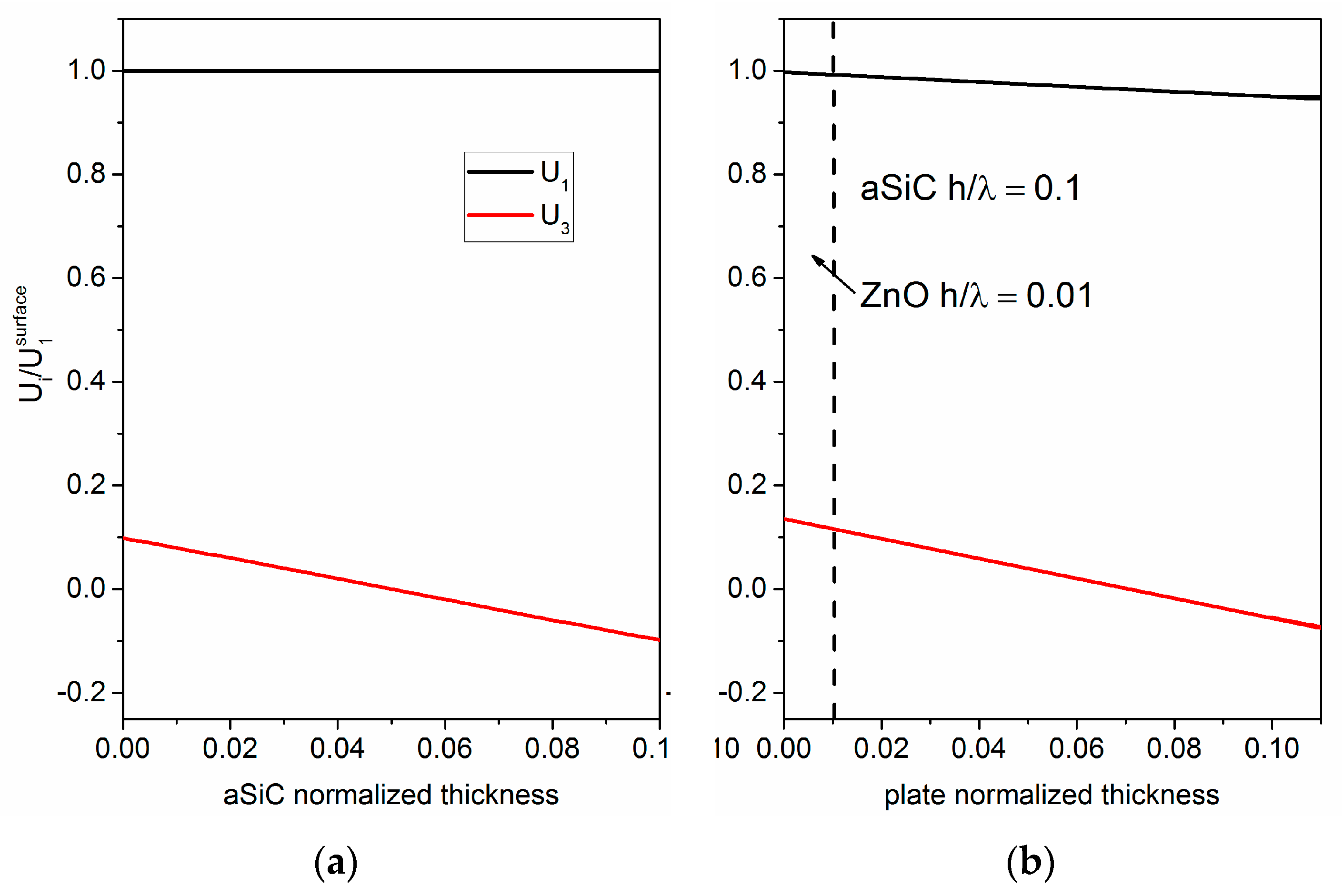
2.1. Acoustic Field Profile

The propagation characteristics of the fundamental symmetric Lamb mode S0 along thin composite plates based on amorphous SiC and piezoelectric c-ZnO layers were studied, aimed at the design of a high frequency electroacoustic device suitable to work in liquid environment. The investigation of the acoustic field profile across the thickness of the a-SiC bare plate revealed that, up to an a-SiC thickness-to-wavelength ratio equal to h/λ = 0.1, the propagating S0 mode have polarization predominantly oriented along the propagation direction. Figure 1a shows the longitudinal and shear vertical particle displacement components, U1 and U3, of the S0 mode propagating along an a-SiC bare plate with thickness-to-wavelength ratio h/λ = 01. U1 is equal to 1 and remains fixed through the plate depth, while U3 is much smaller than U1: the mode is in-plane polarized and thus is suitable for liquid environment applications.
In the composite plate comprising a ZnO layer on top of the a-SiC plate, the S0 mode field profile results quite unperturbed just for a very small ZnO thickness range. Figure 1b shows, as an example, the S0 mode field profile of the composite plate a-SiC/ZnO for h/λ = 0.1 and 0.01 for a-SiC and ZnO, respectively; the mode travels at velocity v = 9892 m/s. As it can be seen, the longitudinal displacement component U1 is almost constant across the composite plate depth, while U3 increases on the ZnO side but it is still negligible on the a-SiC side.
With further increasing the ZnO normalized layer thickness, i.e., 0.02, 0.03, 0.04 and 0.05, the S0 mode velocity decreases (v = 9363.2801 m/s, 8908.8344, 8514.2589, and 8168.038 m/s), the U1 decreases a little at the a-SiC side but still remains greater than U3; the U3 component at the ZnO upper side increases but it decreases at the a-SiC lower side (−0.054, −0.04, −0.03, and −0.022).

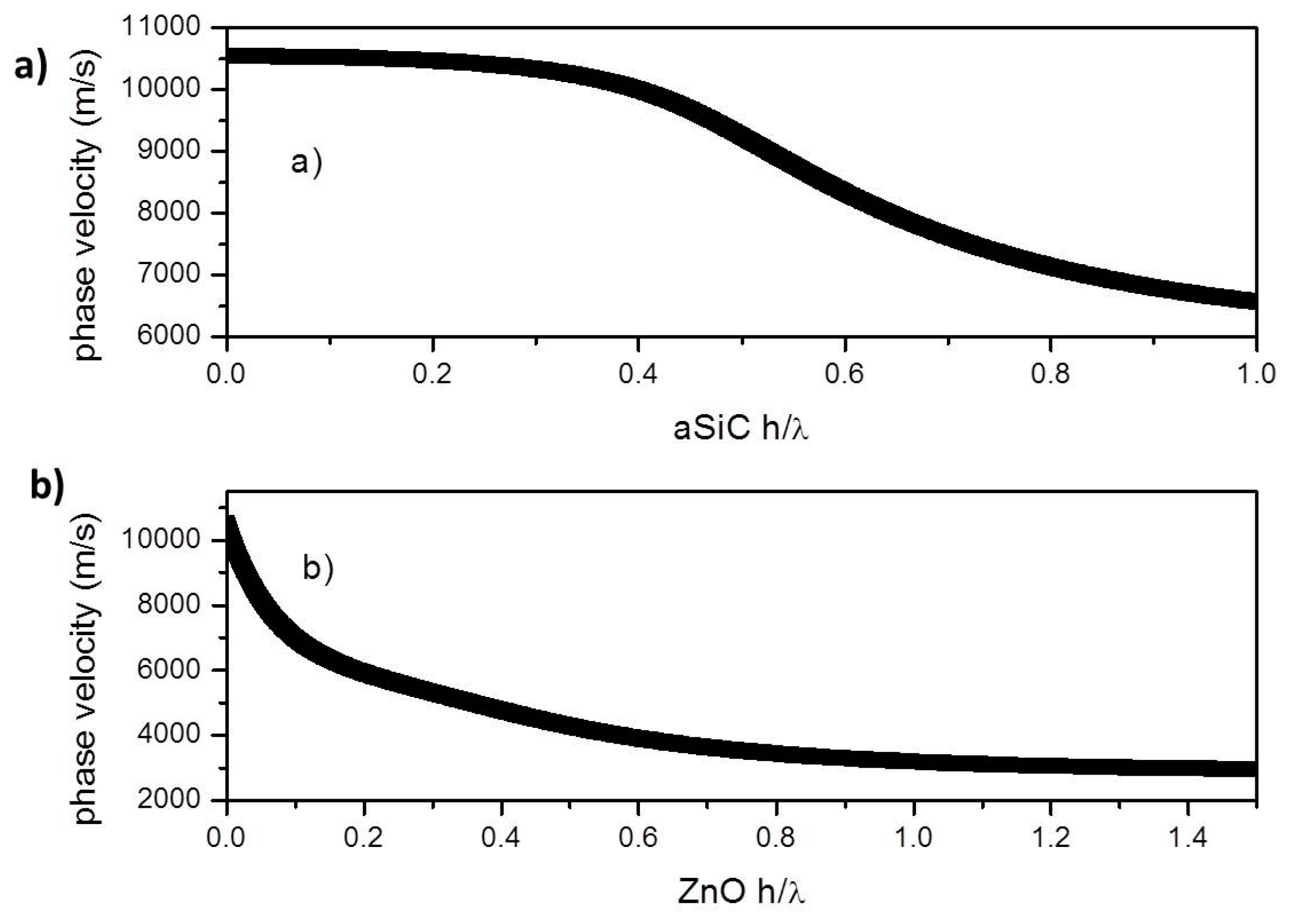
2.2. Phase Velocity Dispersion Curves

The phase velocity of the S0 mode were studied with respect to the a-SiC and ZnO layers thickness: Figure 2a shows the phase velocity dispersion curve of the S0 mode travelling along the bare a-SiC plate; Figure 2b shows the phase velocity of the S0 mode vs. the ZnO normalized thickness, being the a-SiC normalized thickness fixed at 0.1. The theoretical phase velocity dispersion curves were calculated utilizing the ZnO and a-SiC material constants available in the literature [2,3].

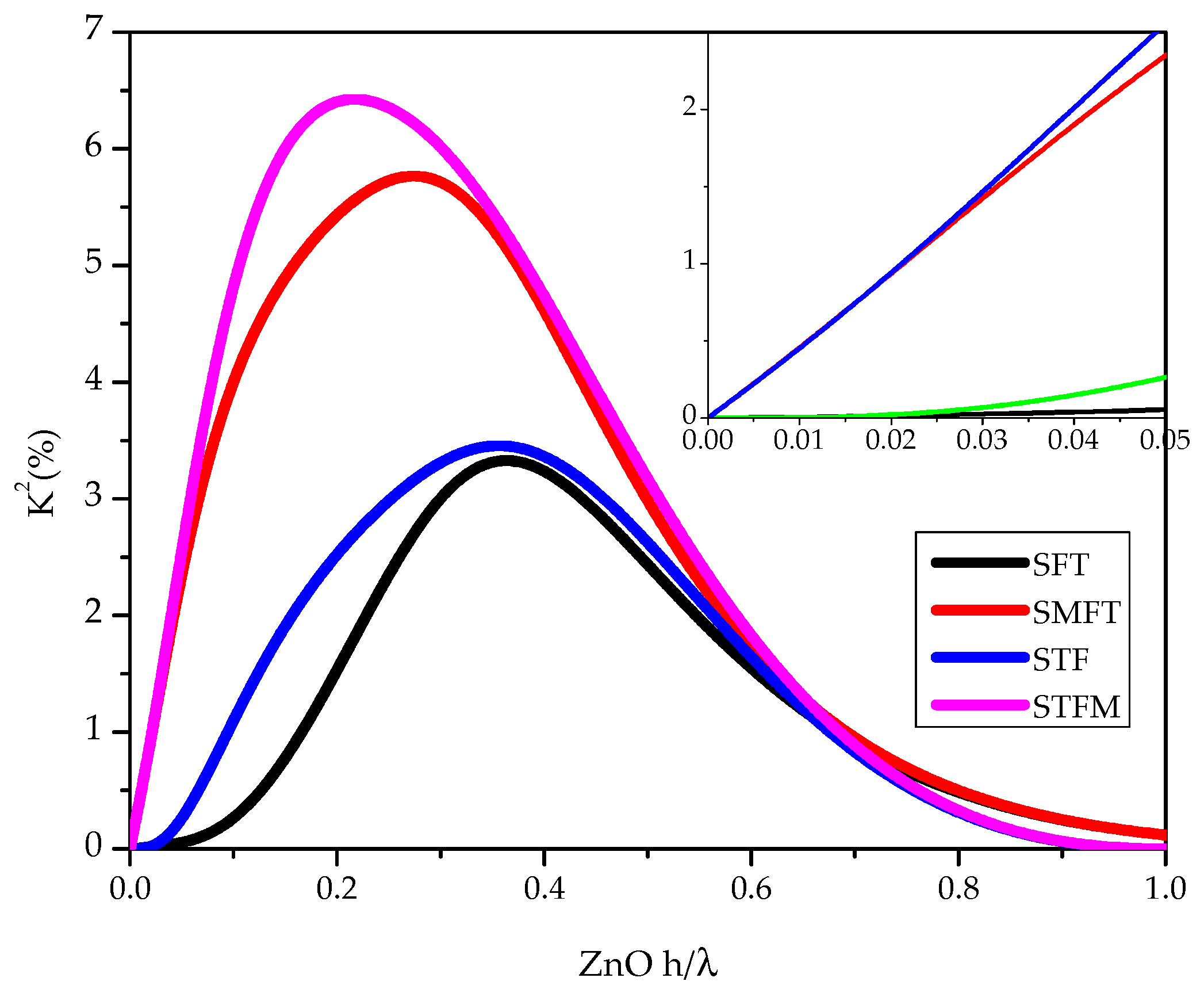
2.3. The Coupling Coefficient Dispersion Curves

In ZnO/a-SiC multilayers, four piezoelectric coupling configurations can be obtained by placing the interdigital transducers (IDTs) at the substrate/film interface (STF) or at the film surface (SFT), further including a floating electrode opposite the IDTs (STFM and SMFT). The four configurations are depicted in Figure 3.
The electroacoustic coupling coefficient K2 of the S0 mode was studied with respect to the a-SiC and ZnO layers thickness and the electrical boundary conditions. K2 can be approximated as 2 ( ( v f v m ) v m   ) , where v f and v m are the velocities along the electrically open and shorted surfaces of the ZnO film. The K2 dispersion curves of each configuration is shown in Figure 4: the a-SiC normalized thickness is fixed (h/λ = 0.1); the abscissa of the graph represents the ZnO normalized thickness. As it can be seen, ZnO/a-SiC-based Lamb mode devices can reach remarkable K2 up to about 6.5%. On the basis of the K2 calculations, the SMFT and STFM coupling configurations have to be preferred since, in the ZnO layer thickness corresponding to the longitudinally polarized S0 mode excitation, these two configuration are highly efficient while the SFT and STF have a low K2, as shown in the inset of Figure 4.

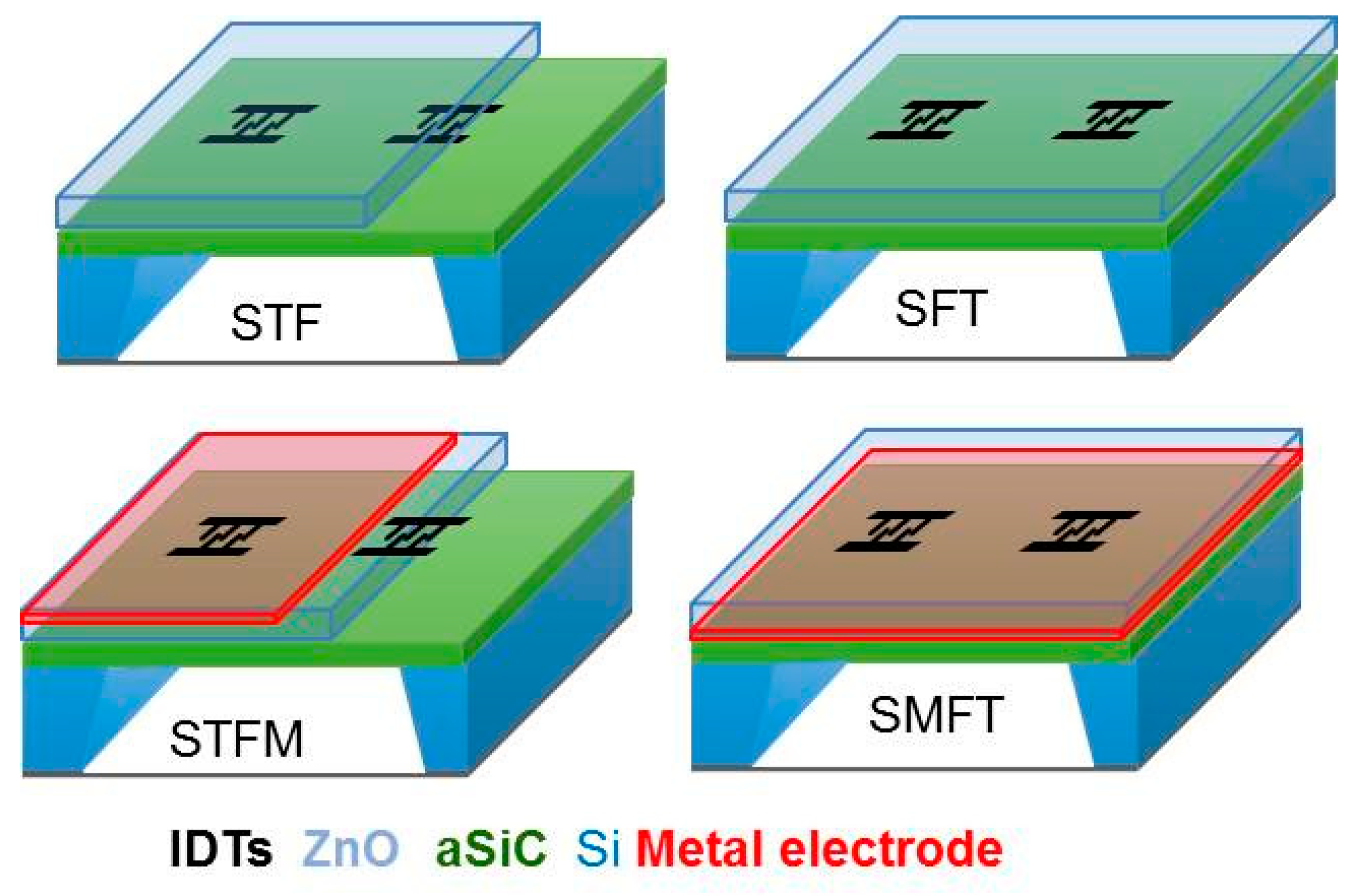
3. S0 Lamb Wave Sensor

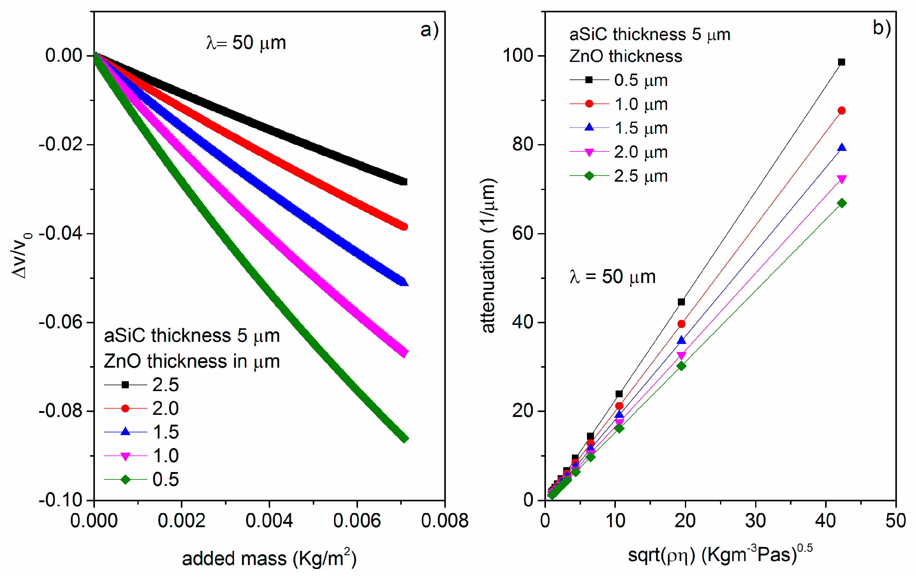
3.1. Gravimetric Sensor

The most common sensing application of the electroacoustic devices is based on the gravimetric principle for mass detection. A mass accumulation on the device surface changes the surface density of the propagating medium, hence resulting in a mode velocity shift. If the added mass consists of an ideal thin elastic film that moves synchronously with the oscillating surface, the fractional-velocity-change to added-mass ratio defines the sensor’s gravimetric sensitivity Sm = ( ( v l v ) v l   ) / m , being m = ρh, ρ and h the added layer’s mass density and thickness, v and vl the unloaded and mass-loaded plate’s phase velocity. Figure 5a shows the relative velocity change vs. added mass in vacuum for different ZnO layer normalized thicknesses (from 0.01 to 0.05) and for fixed a-SiC layer normalized thickness (0.1) and λ = 50 μm. As it can be seen, with decreasing the ZnO thickness from 0.05 to 0.01, the gravimetric sensitivity Sm increases from −41 to −128 cm2/gr, for λ = 50 μm.

3.2. Viscosity Sensor

When a liquid contacts the acoustic waveguide, the in-plane particle displacement component of the acoustic mode couples to a very thin viscous boundary layer of thickness δ = 2 η / ω ρ l , where η and ρl are the liquid viscosity and mass density. We adopted the so called Stokes model for viscous fluids leading to attenuation effects in the longitudinal wave behavior, in accordance with the approximated attenuation per unit length (λ = 50 μm):   α = ω 2 ρ l i q 3 δ 3 3 η d p l a t e ρ p l a t e v S 0 [4]. Figure 5b shows the attenuation vs. the square root of the liquid viscosity and mass density product of glycerol-water mixture. The viscosity sensor is highly sensitive to low viscosity liquids. The working frequencies are 197.839, 187.265, 178.176, 170.284, and 163.404 MHz for the ZnO layer 0.5 to 2.5 μm thick.

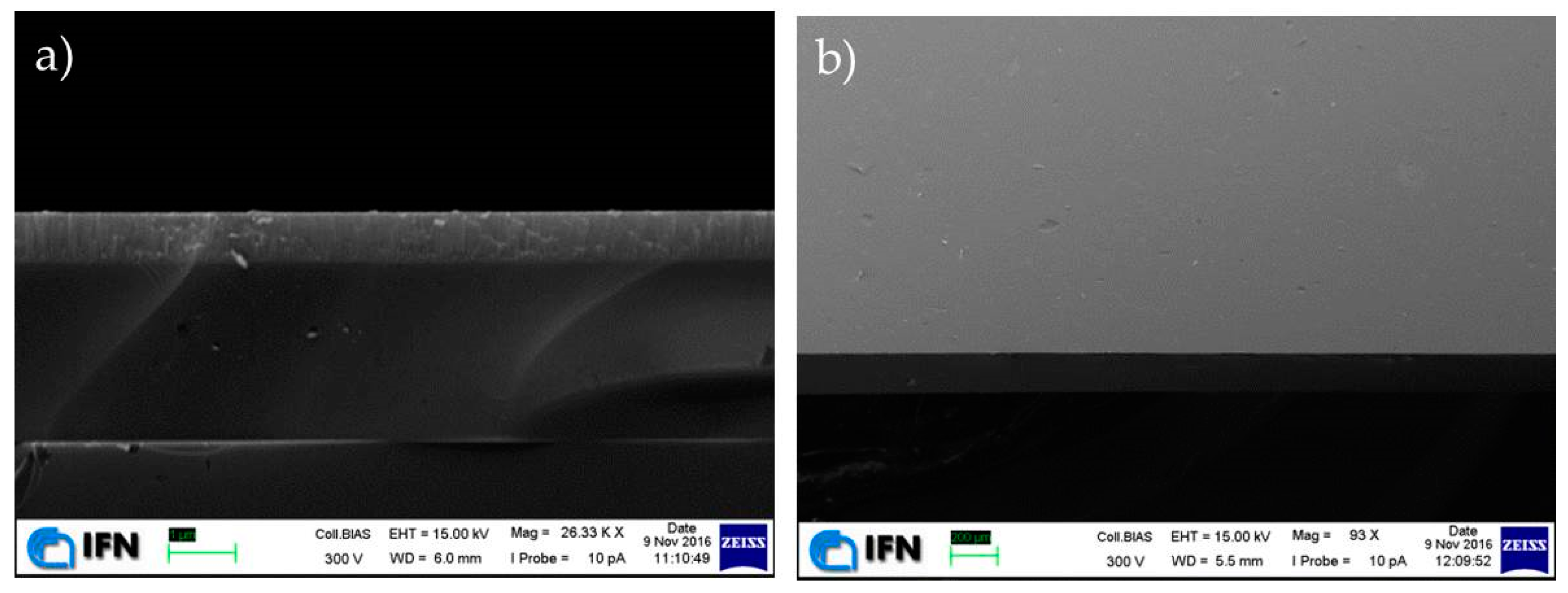
4. A-SiC and ZnO Layers Deposition

The thin a-SiC/ZnO acoustic waveguide theoretically investigated here can be fabricated by using conventional thin film deposition techniques, such as rf sputtering, and bulk micromachining of the Si substrate. The fabrication procedure of this acoustic device offers the advantage of providing the monolithic integration of the device with the signal processing electronics. a-SiC films were sputtered on Si(001) starting from a 4″ diameter SiC target (99.99%) in Ar atmosphere, at 200 °C, rf-power 200 W, pressure 3.0 mTorr. The ZnO films were reactively sputtered on the a-SiC film by a Zn target (99.999%) in Ar/O2 atmosphere at 200 °C, rf-power 200 W, and pressure 3.5 mTorr. The ZnO and SiC films on Si exhibited a good adhesion strength as confirmed by a rudimentary “tape test” with a transparent tape. Figure 6 show the SEM imagines of the cross section and top view of the sputtered a-SiC and ZnO layer on Silicon.
The performed theoretical investigation suggests that a-SiC/ZnO materials combination is a very promising substrate material suitable for developing high-frequency, IC compatible, very simple electroacoustic devices with enhanced K2 and suitable for working in liquid environment.

5. Conclusions

The propagation of the S0 Lamb mode along a-SiC/c-ZnO composite plates have been investigated by theoretical calculation with respect to the ZnO and SiC films thickness and electrical boundary conditions. The phase velocity and the K2 dispersion curves of four ZnO/SiC-based coupling configurations have been theoretically studied specifically addressing the design of enhanced-coupling, microwave frequency electroacoustic devices. The sensitivity of gravimetric sensors based on a-SiC/ZnO plates have been theoretically studied with respect to the a-SiC sensing surface. The attenuation of the S0 mode when contacting a viscous Newtonian liquid has been calculated for different ZnO layer thicknesses. The ZnO/SiC-based sensors are proven to achieve remarkable performances (high sensitivity and enhanced coupling efficiency) that are important prerequisite for the design of future devices, based on resonator principles, to be used in the context of chemical, biological and physical quantities detection.

Author Contributions

C.C. conceived the research, performed the theoretical calculations for Section 2 and Section 3, and wrote the paper. M.H. and F.L. performed the thin film deposition and obtained scanning electron microscope image in Section 4. All authors have read and agreed to the published version of the manuscript.

Acknowledgments

This work was supported by the EU H2020 Project MSCA SAWtrain (Dynamic electromechanical control of semiconductor nanostructures by acoustic fields), Grant agreement No. 642688.

Conflicts of Interest

The authors declare no conflict of interest.

References

  1. Caliendo, C. Theoretical investigation of high velocity, temperature compensated Rayleigh waves along AlN/SiC substrates for high sensitivity mass sensors. Appl. Phys. Lett. 2012, 100. [Google Scholar] [CrossRef]
  2. Hellwege, K.-H.; Hellwege, A.M. Landolt-Börnstein: Numerical Data and Functional Relationships in Science and Technology; New Series, Group III; Springer: Berlin, Germany, 1979; Volume 11. [Google Scholar]
  3. Vashishta, P.; Kalia, R.K.; Nakano, A. Interaction potential for silicon carbide: A molecular dynamics study of elastic constants and vibrational density of states for crystalline and amorphous silicon carbide. J. Appl. Phys. 2007, 101, 103515. [Google Scholar] [CrossRef]
  4. Nayfeh, A.H.; Nagy, P.B. Excess attenuation of leaky Lamb waves due to viscous fluid loading. J. Acoust. Soc. Am. 1997, 101. [Google Scholar] [CrossRef]
Figure 1. (a) the longitudinal and shear vertical particle displacement components, U1 and U3, of the S0 mode propagating at velocity v = 10522 m/s along an a-SiC plate with thickness-to-wavelength ratio h/λ = 0.1; (b) the particle displacement components of the S0 mode propagating at velocity v = 9892 m/s along an a-SiC plate covered by a ZnO layer with thickness-to-wavelength ratio h/λ = 0.01.
Proceedings 01 00021 g001
Figure 2. (a) The phase velocity dispersion curve of the S0 mode travelling along the bare a-SiC plate; (b) the phase velocity of the S0 mode vs. the ZnO normalized thickness, being the a-SiC thickness fixed at 0.1.
Proceedings 01 00021 g002
Figure 3. The four coupling configurations.
Proceedings 01 00021 g003
Figure 4. The K2 dispersion curves of the four coupling configurations for a-SiC normalized thickness h/λ = 0.1.
Proceedings 01 00021 g004
Figure 5. (a) The relative velocity change vs. added mass in vacuum for different ZnO layer normalized thicknesses (from 0.01 to 0.05) and for fixed a-SiC layer normalized thickness (0.1) and λ = 50 μm and (b) The attenuation vs. the η ρ l for different ZnO layer normalized thicknesses (from 0.01 to 0.05) and for fixed a-SiC layer normalized thickness (0.1) and λ = 50 μm.
Proceedings 01 00021 g005
Figure 6. SEM image of (a) Si/a-SiC/ZnO multilayer cross section and (b) Front view of the Si/a-SiC/ZnO multilayer.
Proceedings 01 00021 g006
Publisher’s Note: MDPI stays neutral with regard to jurisdictional claims in published maps and institutional affiliations.

