1. Introduction
The inverted pendulum-cart system remains a paradigmatic benchmark in nonlinear control theory due to its underactuated nature, structural instability, and rich dynamic behavior. This system serves as a standard platform for evaluating advanced control strategies and finds practical applications in robotics (e.g., bipedal locomotion), aerospace (e.g., satellite orientation), and civil engineering (e.g., structural vibration mitigation) [
1,
2,
3].
The fundamental control objective is to stabilize the pendulum around its unstable upright equilibrium by applying horizontal forces to the cart. In recent decades, a wide range of control strategies have been proposed to address this challenge, including proportional-integral-derivative (PID) control, linear quadratic regulators (LQRs) [
4], sliding mode control (SMC) [
5,
6], fuzzy logic [
7], and model reference adaptive control (MRAC) [
8], as well as hybrid and intelligent approaches that integrate multiple control paradigms. These control schemes can be broadly categorized into classical, robust, and intelligent control strategies.
Classical controllers, such as PID, are frequently employed due to their simplicity and ease of implementation. However, they exhibit limited robustness and adaptability. As reported in [
7], while PID controllers achieve faster settling times, they underperform in adaptability compared to fuzzy logic, particularly under varying conditions such as inclined surfaces.
Robust controllers, including LQRs and SMC, provide improved stability and disturbance rejection. LQRs offer guaranteed stability under quadratic cost functions, although their effectiveness depends heavily on the appropriate selection of weight matrices [
4]. SMC, on the other hand, exhibits strong robustness to model uncertainties and external disturbances, and is often combined with observers for state and disturbance estimation [
5,
9].
Intelligent control techniques, such as fuzzy logic, neural networks, and reinforcement learning, have gained traction in recent years for handling system nonlinearities and adaptability challenges. Fuzzy controllers enhance adaptability compared to PID [
7]. Hybrid approaches that combine energy-based swing-up control with LQRs or SMC have been proposed for complex configurations such as rotary or double inverted pendulum systems [
6,
10]. Reinforcement learning methods, including Q-learning adapted to continuous control domains, have shown promise in simulation environments [
11], although they remain sensitive to modeling inaccuracies and hardware constraints.
Robust and intelligent controllers continue to evolve. For instance, adaptive fuzzy terminal sliding mode control (AFFTSMC) [
9] demonstrates experimental fault tolerance and reduced chattering. In [
12], a second-order sliding mode controller is used to stabilize a pendulum mounted on an omnidirectional mobile robot, achieving semi-global asymptotic stability. Neural-based PID (PIDNN) architectures, optimized using Ant Colony Optimization [
13], exhibit improved tracking and robustness compared to PSO-tuned PID/FOPID schemes, although they introduce increased model complexity and typically lack hardware validation. Experimental comparisons in [
14], using an Arduino-based platform, demonstrate that both indirect adaptive control (IAC) and neuro-fuzzy control (NFC) outperform PID in terms of robustness and transient response.
While several advanced nonlinear control strategies have been proposed in recent years—such as BELBIC [
15], fuzzy brain emotional learning controllers (FBELC) [
16], neural PID structures [
13], and deep reinforcement learning (DRL) approaches [
17]—they still present major limitations. These include reliance on trial-and-error tuning [
15], increased structural and computational complexity [
16], and strong sensitivity to hyperparameter selection and model architecture [
17]. Moreover, many of these methods are data-driven and lack analytical guarantees for convergence and stability, which limits their applicability in safety-critical real-time systems.
In contrast,
fractional-order control has emerged as a novel and promising approach that offers a sound mathematical foundation with greater flexibility for tuning and improved robustness. By generalizing classical calculus to non-integer orders, fractional-order controllers introduce additional degrees of freedom in controller design [
18,
19]. Among them, the fractional-order PID (FOPID) controller extends the classical PID by incorporating fractional-order integrals and derivatives, enabling improved performance in the presence of model uncertainties and disturbances. Experimental studies, such as [
20], validate its effectiveness in various real-world settings without requiring changes to model order. Recent works have applied metaheuristic optimization techniques—such as Particle Swarm Optimization (PSO), genetic algorithms, and differential evolution—to fine-tune FOPID parameters for multi-objective performance indices, including ITSE, settling time, and rise time [
21,
22]. These results confirm that fractional-order strategies can outperform conventional PID and many existing nonlinear controllers in both performance and adaptability.
Despite these advances, an important research gap persists: the integration of
fractional-order gradients (FGs) into adaptive control frameworks like model reference adaptive control (MRAC). While FG methods have demonstrated improved convergence rates in optimization and machine learning applications [
23], their incorporation into real-time adaptive control—particularly for nonlinear systems—remains largely unexplored. Recent work [
24] has introduced a first-order fractional error model with fractional gradients (FOEM1–FG), showing encouraging results in simulations and initial experimental validations. The present paper aims to build upon this foundation, offering a systematic development and analysis of a novel fractional gradient-based MRAC scheme with theoretical guarantees and practical relevance.
In this paper, we address this gap by proposing a novel fractional-order error model (FOEM) framework that systematically embeds Caputo fractional gradients into the parameter adaptation law. Two new formulations, FOEM2–FG and FOEM3–FG, are presented and analyzed using Lyapunov stability theory. The proposed controller is tuned using a multi-objective PSO algorithm and validated using simulations and real-time experiments on an inverted pendulum-cart system.
The main contributions of this work are as follows:
The formulation of two original architectures, FOEM2–FG and FOEM3–FG, that incorporate fractional gradients into the adaptive law via Caputo derivatives. This contribution systematically extends classical adaptive control theory to fractional-order systems.
A rigorous Lyapunov-based stability and convergence analysis demonstrating boundedness of the tracking error and asymptotic convergence under persistent excitation.
Extensive validation using simulations and real-time experiments, showing that the proposed FOEMRAC strategy outperforms conventional MRAC, PID, and FOPID controllers in tracking accuracy and convergence speed.
The paper is organized as follows:
Section 2 introduces the fundamentals of fractional calculus and fractional gradient methods.
Section 3 formally defines the fractional-order error models (FOEM1–3) using Caputo derivatives and the Lyapunov-based stability and convergence analysis.
Section 4 presents the case study and experimental validation, discussing the results and implications of fractional-order MRAC in underactuated nonlinear systems. Conclusions are presented in
Section 5.
4. Results and Simulations
4.1. Case Study: The Inverted Pendulum
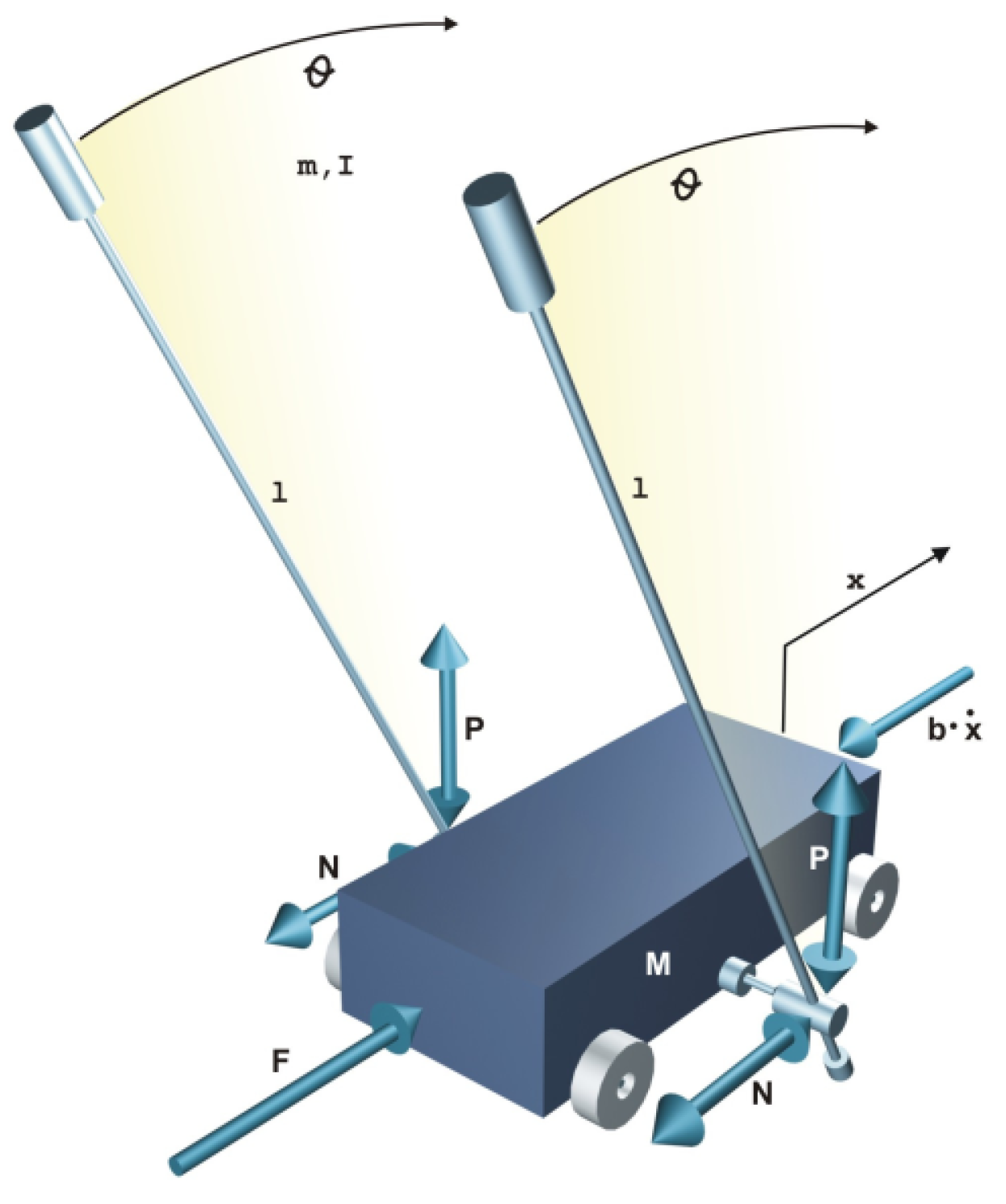
The advantages of the FOEM3-FG are examined in an experimental case of study: the inverted pendulum (InvP). The InvP is a servomechanism consisting of a pivot, which can swing freely about its axis and is mounted on a carriage (
Figure 4). The carriage moves along a horizontal axis within a finite range, generating thus an oscillation in the pendulum. The objective is to keep the pendulum vertical and maintain it at equilibrium by implementing a control system [
36]. Fractional-order PID (FOPID) controllers have already been experimentally validated in this plant [
37].
The carriage’s movement is generated by the traction of a chain coupled to the shaft of a direct current (DC) motor located at the end of the rail. Applying voltage to the motor allows for the carriage’s movement to be controlled in both directions. The two variables measured in the system using optical encoders are the carriage’s position and the pendulum’s inclination angle.
Table 1 shows the parameters of the pendulum-cart system used in this study.
The control signal is limited in the range and the magnitude of the generated force varies in the interval . The length of the rail physically limits the position of the carriage and is equal to .
The phenomenological model of the inverted pendulum is presented in Equation (
47). By adding the forces acting on the pendulum and cart system, as well as the moments, the following nonlinear equations of motion are derived:
where
x [m] is the cart position corresponding to the center of the rail,
[rad] is the pendulum angular position concerning the vertical axis,
g is the gravitational acceleration,
l is the pendulum length,
M is the mass of the cart,
m is the mass of the pendulum,
I is the moment of inertia,
b is the friction coefficient of the cart,
d is the viscous friction coefficient of the pendulum, and
F is the force applied to the cart by the motor and corresponds to the input to the system. The parameter values are listed in
Table 1. For the simplicity of presenting our theoretical results, the control input
used in the inverted pendulum state model is the force exerted on the cart,
.
Next, we will analyze the equilibrium states of the pendulum and their effects on the phenomenological model. The pendulum has two equilibrium points: one occurs when (inverted pendulum, unstable system), and the other occurs when (freely suspended, stable system). To demonstrate the applicability of the proposed adaptive controller, we will focus on the linearized model for the operating point . The position of the cart, denoted as x, will be controlled by letting the angle hang freely.
4.2. Linearized Model for Equilibrium Point
To linearize the system with respect to the equilibrium point
, the following substitutions are made:
resulting in
Building the matrices in the state variable, we obtain
with the state vector
defined as
The state matrices (
,
) and output matrices (
) become
where
4.3. Parameters Tuning
The controller parameters are tuned using the Particle Swarm Optimization (PSO) algorithm [
38]. PSO is a population-based metaheuristic method inspired by swarm intelligence. It mimics the social behavior of a biological population (such as insects, birds, or fish) in their search for food. According to its creators, each individual (particle) interacts with another, exchanging experiences, so that the group will gradually move into better regions of the search space [
38].
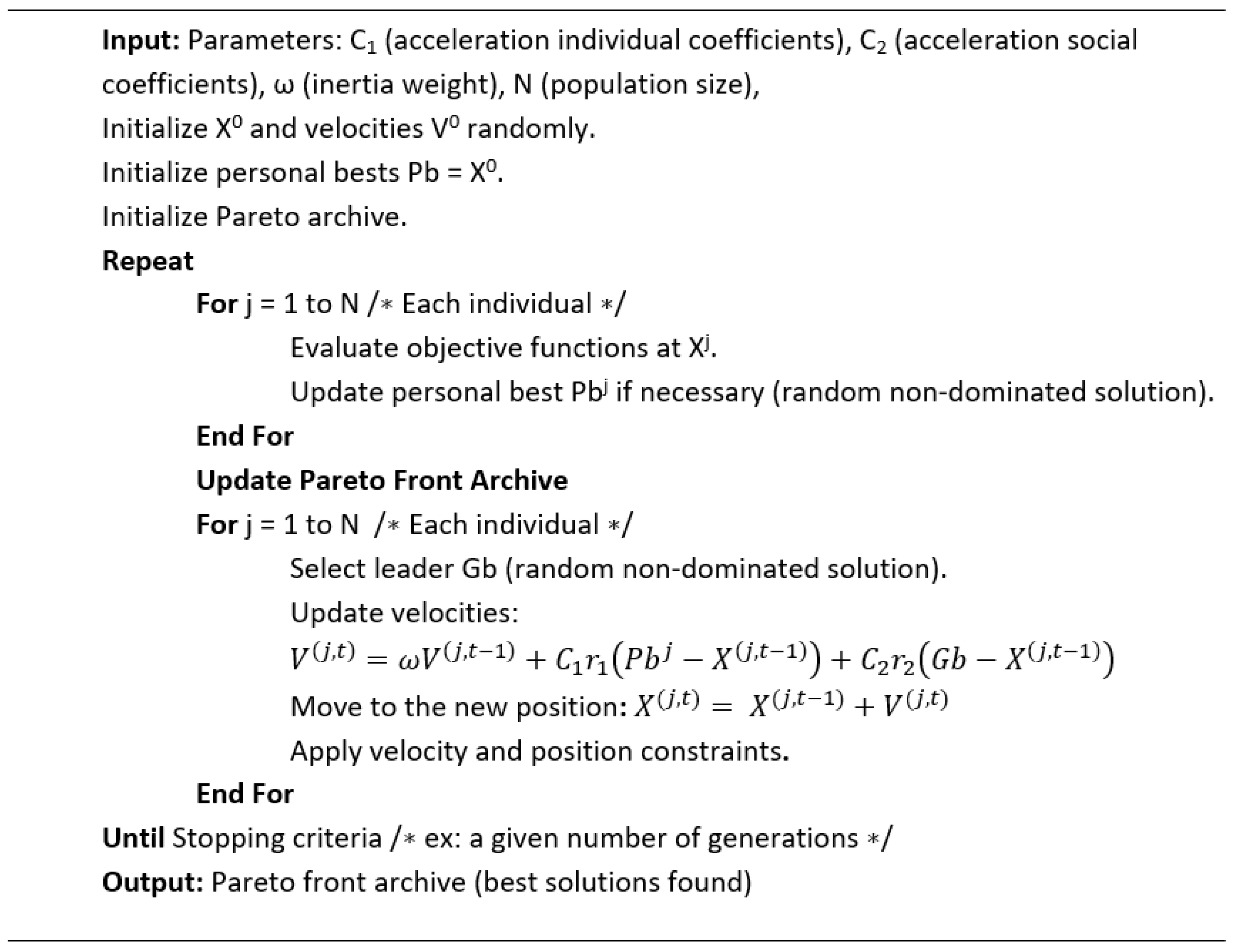
In PSO,
Figure 5, the solution search for each particle is defined by the update of its speed and position inside the swarm, which are established as follows:
where
N and
T are the number of particles of the swarm and the number of iterations, respectively.
V and
X are the speed and the position of the particle (i.e., the candidate solution),
and
are the acceleration coefficients (individual or population),
is the best position found by the particle in previous iterations,
is the best position found by the population,
and
are uniformly distributed random numbers in the interval
used to keep the population diversity, and
is the inertial weight.
A high value of implies greater exploration of the search space and a longer convergence time. In contrast, a small value reduces convergence time, but increases the risk of getting trapped in a local optimum. The value of is typically set to decrease linearly, promoting greater exploration at the beginning of the algorithm and greater exploitation of the solutions found as the search progresses.
In this work, a multi-objective problem is defined. A first primary objective function is defined as the Integral of Squared Error (ISE):
where
represents the control error, computed as the difference between the reference signal
and the system output
, i.e.,
. A lower ISE indicates better tracking performance and improved accuracy.
Then, a second objective function is defined as the Quantitative Total Variation (QTV). The QTV metric is used to evaluate the variability of the control signal
, reflecting the aggressiveness of its variation over time. The QTV is defined as
where
is the control signal by the instant
t and
N is the total number of samples, taken with a sampling time of 0.001 s.
is focused on minimizing highly abrupt behavior.
Although it is possible to aggregate the two objectives ( and ) into a single weighted cost function, this study employs a Pareto-based approach to preserve the trade-offs between competing objectives. To this end, a Multiobjective Particle Swarm Optimization (MOPSO) algorithm is applied, which extends the classical PSO framework to handle multiple objectives simultaneously. Key modifications include the following:
Maintaining an archive of non-dominated (Pareto-optimal) solutions found throughout the optimization process.
Selecting a random leader from the Pareto front to maintain solution diversity and prevent premature convergence.
In MOPSO, each particle represents a candidate controller configuration defined by parameters such as gains or fractional orders. The algorithm evaluates each configuration using simulations of the cart-pendulum system, computing ISE and QTV as objective metrics for tracking accuracy and trajectory smoothness. These values define the fitness function, allowing for the construction of a Pareto front with non-dominated solutions. Particle positions and velocities are iteratively updated until a stopping criterion is met, enabling the simultaneous optimization of both performance objectives.
Three key performance indices—Integral of Squared Error (ISE) (
54), Quantitative Total Variation (QTV) (
55), and Integral of Squared Input (ISI)—are used to quantitatively evaluate the control performance of the different controllers implemented on the inverted pendulum-cart system. These indices measure tracking accuracy, control signal smoothness, and control effort.
The Integral of Squared Input (ISI) measures the energy associated with the control signal and is defined as
A lower ISI implies reduced control effort and energy consumption, which are critical in real-time embedded systems and power-sensitive applications.
These indices collectively allow for a comprehensive evaluation of control performance, balancing accuracy (ISE), smoothness (QTV), and effort (ISI).
4.4. Controllers Design
4.4.1. PID and FOPID Controllers
The manufacturer provides a PID controller for controlling the car’s movement on the rail [
36]. Since the manufacturer’s PID effectively meets the control objective, the performance of this controller will serve as a reference for the other designed controllers. The PID equation is described as follows:
To construct the fractional order of the FOPID controller, as shown in Equation (
58), we utilize the structure of the manufacturer’s PID controller, but with fractional parameters. The fractional parameters, denoted as
and
, are optimized using Multiobjective Particle Swarm Optimization (MOPSO). The numerical values for the PID and FOPID controllers are defined in
Table 2.
A value of
indicates that the FOPID controller essentially behaves as a FOPI controller, since the derivative action effectively becomes a proportional action. It is also interesting to note that
is greater than one, corresponding to the integer-order integration.
4.4.2. MRAC and FOMRAC Controllers
With the aim of controlling the position of the car
, without concern for the angular position of the pendulum, we include integral tracking of reference error, thus resulting in an extended state plant model given by
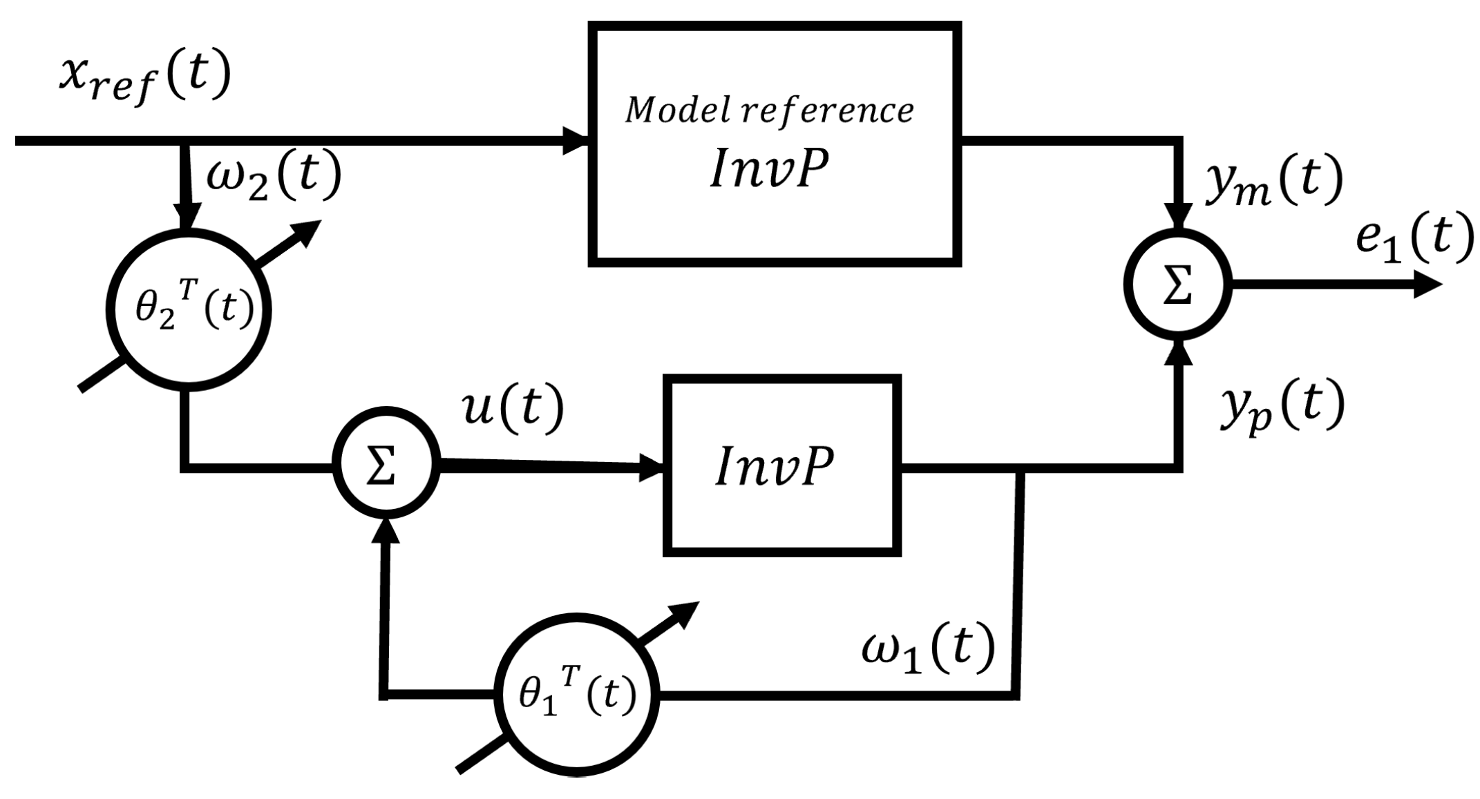
the reference model for the design of the MRAC [
39] is defined as follows:
where
and where the gain K is defined by linear quadratic regulator (LQR) methods that keep the system stable.
The control signal is defined as
where it is a negative linear combination of the information vector
, weighted by adaptive parameters.
The control error is defined as the difference between the plant output in Equation (
50) and the reference model described in (
60), and the error dynamic
is defined in Equation (
7), with the corresponding adjustment law:
with
, where
and
. The model reference adaptive control described by Equations (
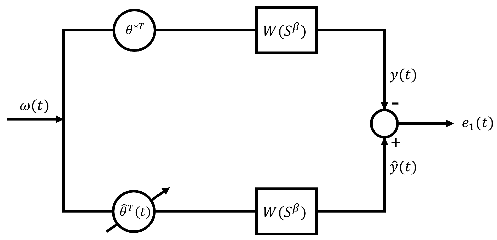
7) and (
62), illustrated in
Figure 6, corresponds to the FOEM3-FG, as complete access to the system output state vector is not available.
For the design of the integer-order MRAC, the tuning of
and
is performed individually, as separating the output error gains from the parameter adaptation gains proves to be more beneficial. The control signal is given by
with the error model
and adaptation law
defined in Equations (
7) and (
62), respectively, and the information vector equal to
. When
and
, the formulation corresponds to the standard MRAC. In contrast, when
and
differ from 1, the method corresponds to the fractional-order variant, FOMRAC.
4.4.3. Simulations for the System of the Inverted Pendulum
Fractional operators were implemented using the Ninteger toolbox for MATLAB [
40], specifically through the NID block, which approximates fractional-order transfer functions. Since the NID block does not handle initial conditions by default, the Caputo definition of the fractional derivative and relevant properties of fractional integrals were adopted in order to incorporate the system’s initial states correctly.
The NID block operates based on the Oustaloup recursive approximation method. For this implementation, a configuration of ten poles and ten zeros was selected, with a frequency range of rad/s to ensure a reliable approximation across the operating bandwidth.
For all simulations, the initial conditions placed the cart at the center of the rail, while the pendulum started from the inverted position (
from the vertical) and at rest. The simulation time was set to 60 s. The values of the linear quadratic regulator (LQR) matrices
and
, as well as the gain matrix
K, were defined using LQR methods to ensure closed-loop system stability.
where the gain
K is equal to
. The numerical values for the MRAC and FOMRAC controllers are defined in
Table 2.
Table 2.
Numerical values of the parameters for the PID, FOPID, MRAC, and FOMRAC controllers.
Table 2.
Numerical values of the parameters for the PID, FOPID, MRAC, and FOMRAC controllers.
| Controller | | | | | | | | | |
|---|
| PID | 27.3 | 50 | 3.9 | 1 | 1 | – | – | – | – |
| FOPID | 27.3 | 50 | 3.9 | 1.15 | 0.02 | – | – | – | – |
| MRAC | – | – | – | – | – | 594.44 | 632.85 | 1 | 1 |
| FOMRAC | – | – | – | – | – | 2.95 | 8.13 | 0.38 | 1.71 |
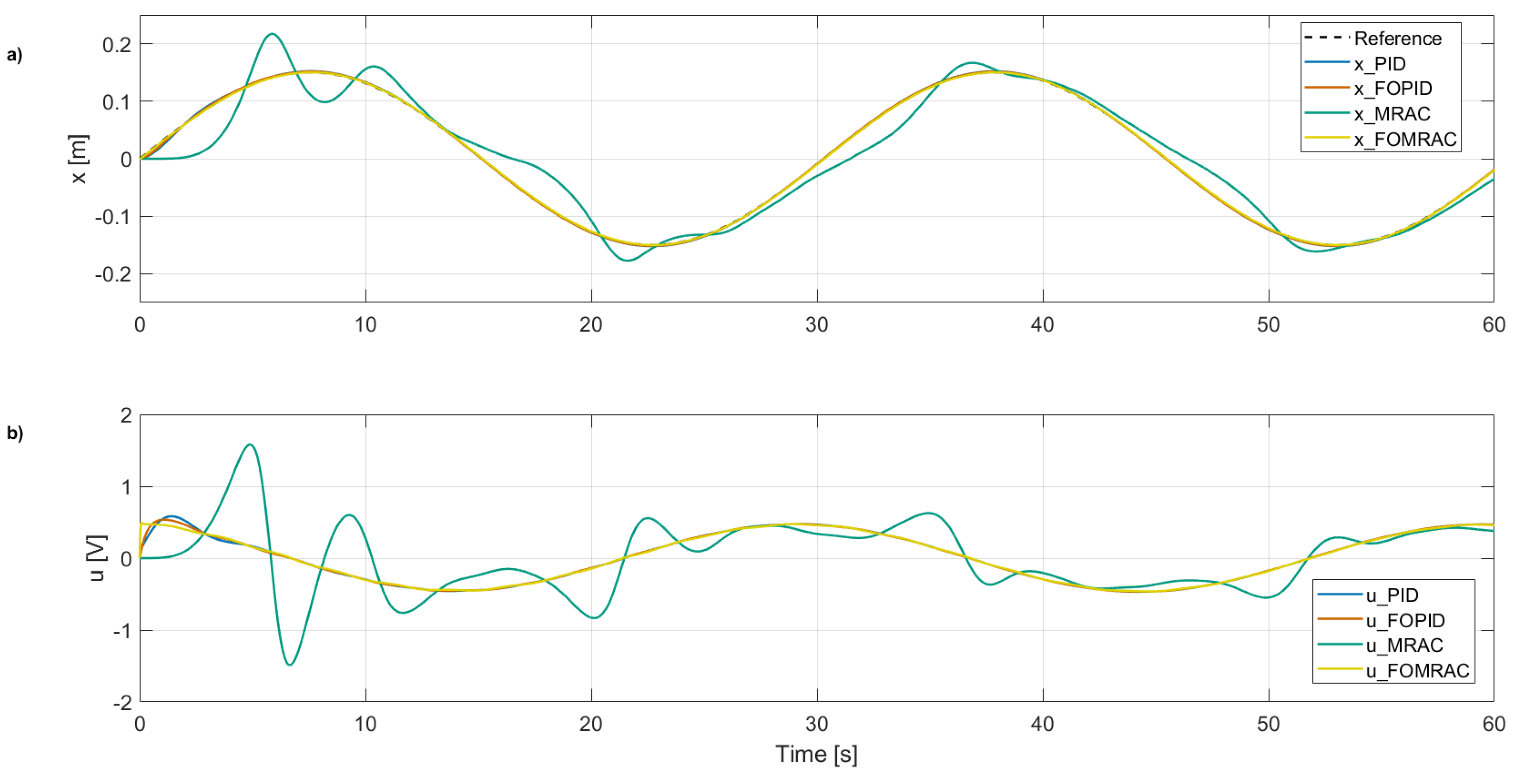
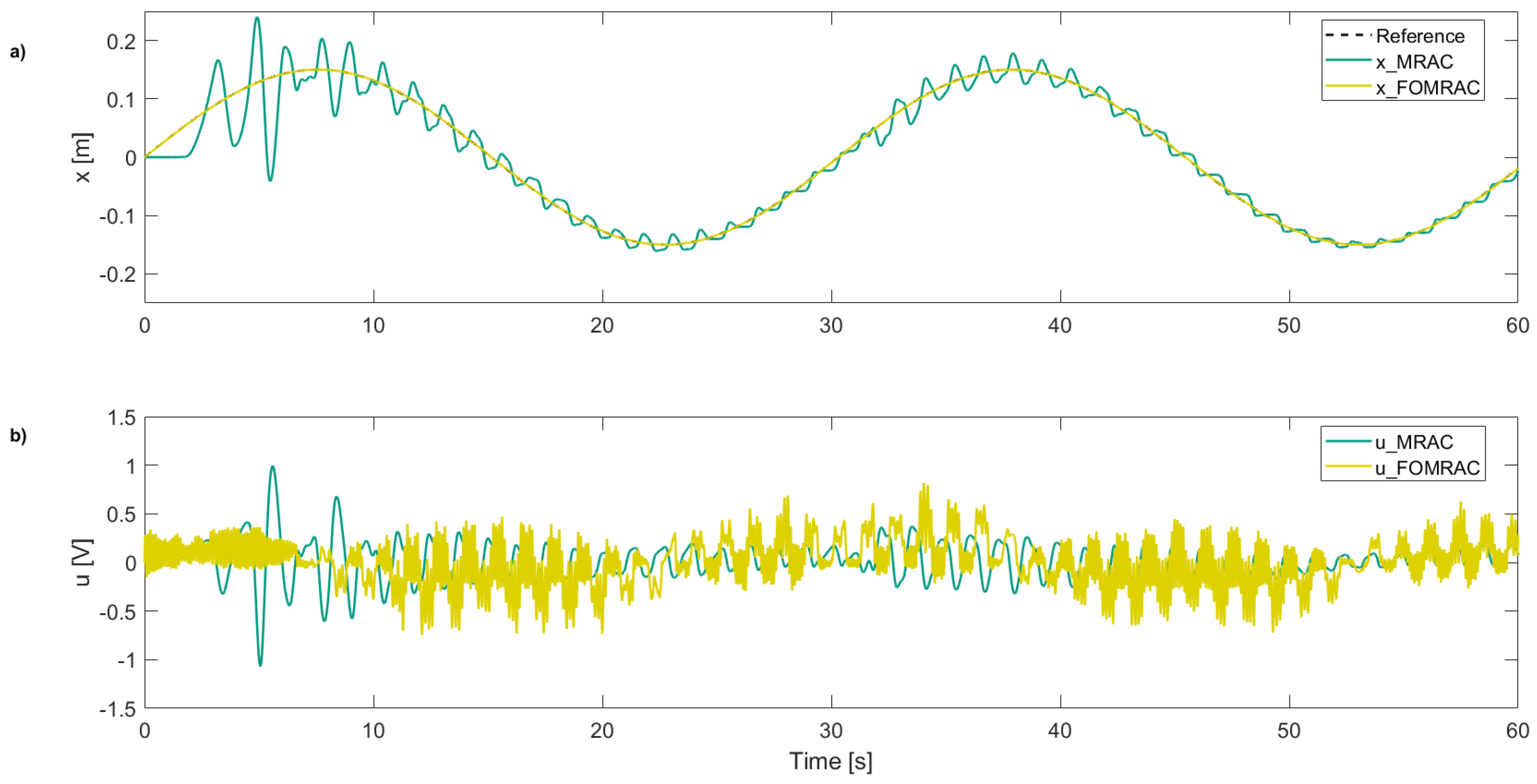
Figure 7 shows the pendulum position control simulation in response to a sinusoidal reference input, defined as
, and the corresponding control signal
generated by the four designed controllers (PID, FOPID, MRAC, and FOMRAC).
Table 3 presents a comparative analysis using the performance indices defined in
Section 4.3.
In
Figure 7a, which shows the cart position
x over time, the conventional MRAC controller exhibits significant overshoot and oscillatory behavior, indicating a less robust response to the system’s nonlinear dynamics. The FOPID controller improves damping and reduces oscillatory behavior, but still displays a delayed and less accurate tracking of the reference. However, it achieves the best QTV score (
Table 3). The proposed FOMRAC controller demonstrates the best tracking performance, following the desired reference with minimal error and the fastest convergence, as reflected by its superior ISE value (
Table 3).
Figure 7b presents the control signal in volts. The MRAC controller generates the most aggressive control action, characterized by high peaks and rapid variations, which may lead to increased energy consumption and actuator wear. The FOPID controller provides a moderately smoother control effort, but exhibits noticeable transients. In contrast, the FOMRAC controller produces the softest and most efficient control signal among all methods, with minimal amplitude and variation, corresponding to the best ISI score (
Table 3). This suggests a more energy-efficient use of control effort while maintaining high trajectory-tracking performance. Overall, the FOMRAC strategy outperforms the others in both reference tracking and control efficiency. Although the FOPID controller exhibits the best Quadratic Tracking Variation (QTV), the FOMRAC’s performance remains comparable and well-balanced across all indices.
Including fractional-order gradients markedly enhances the adaptability and robustness of the control scheme, resulting in a notably smoother transient response. As shown in
Table 2, the adaptive gain values
and
required for the FOMRAC controller are significantly lower than those needed for the conventional MRAC approach. Despite these lower gains, FOMRAC not only outperforms the classical MRAC in terms of stability and tracking precision, but also delivers performance comparable to—and in some cases exceeding—that of the
controller. These results demonstrate that incorporating fractional calculus into adaptive control strategies introduces additional degrees of freedom that enhance flexibility, robustness, and overall control performance, particularly in scenarios where integer-order methods prove insufficient.
4.4.4. Experimental Simulations for the System of Inverted Pendulum
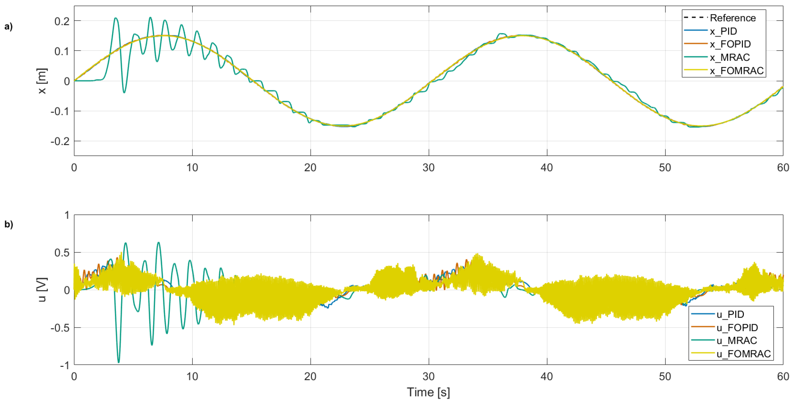
The experimental results presented in
Figure 8 were obtained experimentally in the research group’s laboratory using the inverted pendulum model provided by Feedback Instruments [
36].
In
Figure 8a, the cart position
x reveals a clear contrast between the control strategies. As observed in simulation, the MRAC controller (green) continues to display overshoot and oscillations, indicating limited robustness in handling real-world nonlinearities and noise. The FOPID controller (orange) improves greatly, reducing oscillatory behavior and showing a more stable trajectory than MRAC, obtaining the best QTV. The proposed FOMRAC controller (yellow) also accurately tracks the reference trajectory, achieving the best ISE. Despite the increased variability inherent in the physical setup, it minimizes the tracking error over the full time horizon and exhibits faster convergence than the other methods.
Figure 8b shows the control signals in volts. The control effort of the MRAC exhibits the highest amplitude signal, although it remains within the permissible range of the DC motor. The FOPID signal has a lower amplitude than the MRAC and achieves the best ISI (see
Table 4), although it still displays visible transients. In contrast, the FOMRAC controller, in its practical implementation, produces control actions with more frequent abrupt changes than the other methods. Although the inverted pendulum setup applies constraints such as slew rate limiting, high-frequency filtering, and dead zone compensation to protect the motor from overvoltage, current spikes, and excessive wear, this behavior suggests a potential area for improvement in the FOMRAC design, since its control signal could impose considerable stress on the actuators in real-world applications. Overall, the FOMRAC strategy demonstrates superior experimental performance in precise reference tracking, even if this entails larger variations in the control signal, thereby validating the advantages of incorporating fractional-order gradients into adaptive control laws.
4.4.5. Experimental Simulations for the System of the Inverted Pendulum with Disturbances
To validate the robustness of the designed controllers against disturbances, simulations were carried out in which the pendulum was displaced from its stable equilibrium position at to . This scenario represents a significant alteration of the system dynamics and allows for assessments of how each control strategy maintains trajectory tracking performance under adverse conditions.
In the case of the PID controllers, both the classical integer-order and the fractional-order variants (see
Figure 9a), it is observed that reference tracking is noticeably affected during the application of the disturbance. This performance degradation manifests as small oscillations superimposed on the reference trajectory, which tend to diminish progressively as the controllers increase the control action to compensate for the error. This behavior is numerically reflected in the performance indices presented in
Table 5, where an increase in the ISE is evident. Likewise,
Figure 9b shows that this compensation involves a considerable increase in the control signal amplitude and its transients, reflecting additional control effort that could compromise energy efficiency and actuator lifespan if sustained over time.
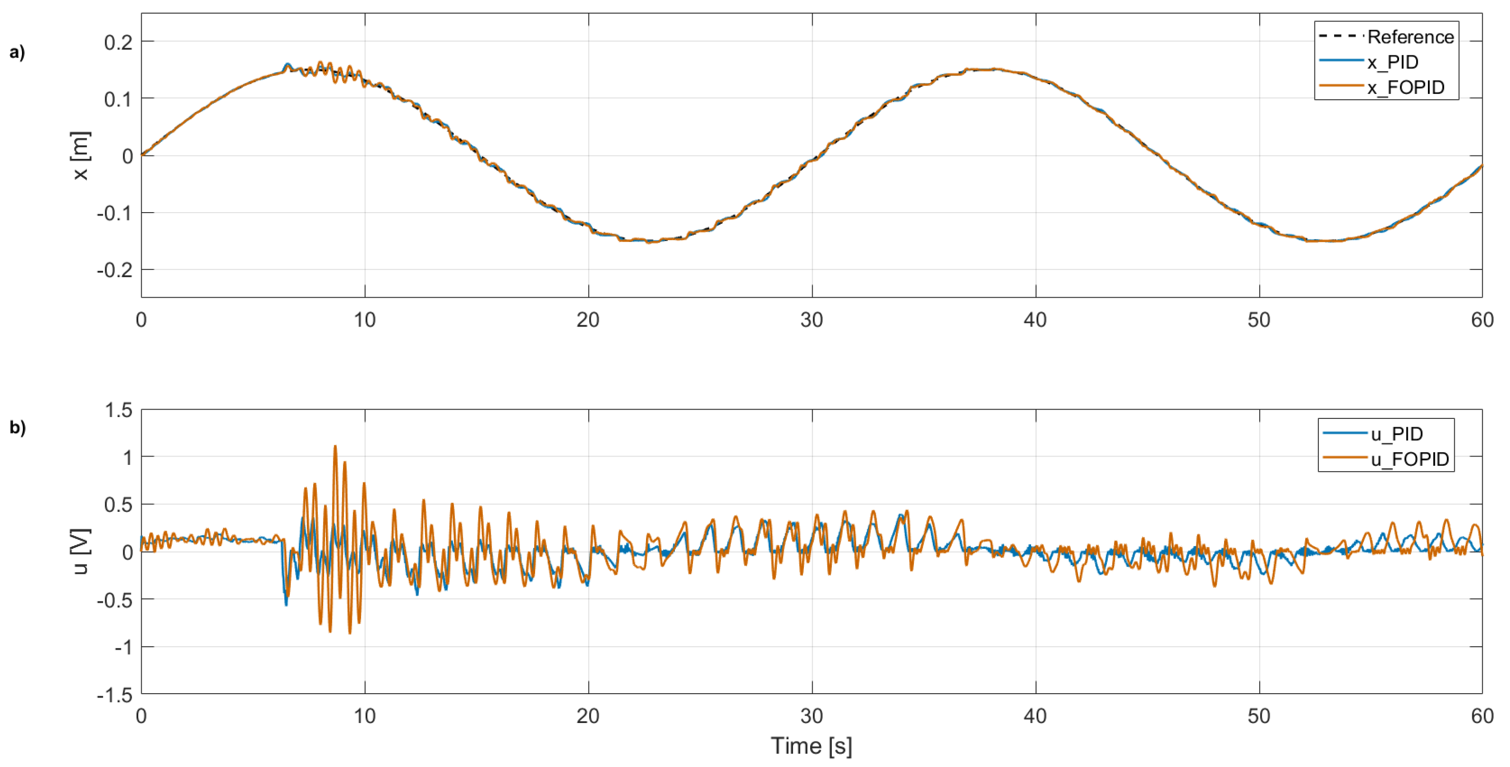
In the case of the conventional MRAC controller (
Figure 10a), the system initially exhibits oscillations that gradually decrease until, after second 30, the disturbance is applied. The system then experiences a rise in oscillations around the reference, accompanied by a sustained increase in the control signal amplitude (
Figure 10b). This increase highlights the limited capability of the conventional MRAC to dynamically adapt to abrupt changes in operating conditions, partially compromising tracking performance.
In contrast, the FOMRAC controller demonstrates more robust behavior against the disturbance. Although an increase in the magnitude of the control action is observed in the control signal (
Figure 10b) when compensating for the perturbation, the reference tracking remains practically unaffected, without additional noticeable oscillations in the trajectory. This result is quantitatively corroborated in
Table 5, where the FOMRAC achieves the lowest ISE among all evaluated controllers, confirming its ability to maintain high-precision tracking despite sudden variations in the system dynamics. This superior performance is attributed to the combination of the adaptive law based on fractional gradients and the greater flexibility introduced by the non-integer order parameters, which enable a smoother and more efficient response to external disturbances.
In future work, the proposed fractional-order adaptive control strategies (FOEM2-FG and FOEM3-FG) could be extended beyond the inverted pendulum to a broader class of nonlinear and underactuated systems. For example, integrating fractional-order MRAC schemes with robust controllers, such as fractional-order sliding mode control (FOSMC), offers a promising research direction for differential-drive mobile robots subject to skidding, slipping, and unknown disturbances [
41]. In this context, fractional gradient-adaptation laws can enable the online estimation of uncertain dynamic parameters without requiring prior knowledge of disturbance bounds, thereby enhancing adaptability and tracking performance under highly variable operating conditions. Such hybrid controllers may significantly improve convergence speed, disturbance rejection, and control smoothness in applications including payload stabilization in aerial drones, trajectory tracking in ground vehicles, and precise manipulation in robotic arms [
42]. Further research will focus on developing composite Lyapunov-based stability proofs and experimentally validating the proposed methods on real-time embedded platforms.
5. Conclusions
This paper introduced two adaptive control strategies—fractional-order error models 2 and 3—incorporating a fractional gradient. Model 3 extends model 2 by relaxing the requirement of full plant knowledge, making it more suitable for practical implementations. Theoretical foundations for stability and convergence were established based on the Caputo fractional derivative, and the proposed methods were applied to the position control of an inverted pendulum system.
The experimental and simulation results demonstrate that, while the classical PID controller fulfilled the basic control objectives, it was outperformed by controllers utilizing fractional calculus. The FOPID controller, in particular, exhibited improved damping and smoother control signals compared to PID, highlighting the benefits of fractional-order dynamics for improving transient behavior.
Although the MRAC controller was developed based on a linearized model, its performance suffered from overshoot and aggressive control action both in the simulation and on the real system, suggesting limited robustness to nonlinearities and disturbances. In contrast, the proposed FOMRAC controller, which integrates the fractional gradient, achieved superior performance in both scenarios. It delivered more accurate trajectory tracking and enhanced disturbance rejection capabilities, validating the effectiveness of the fractional-order adaptive control framework in handling real-world nonlinear systems with greater precision, resilience, and efficiency.

