
A Multidisciplinary Approach to Triangular Shapes: Philosophy, Art, Mathematical Properties, and Application Purposes for High-Frequency Signal Processing Using Sierpiński Geometry †


Abstract
1. Introduction
2. Philosophy, Mathematics, and Art
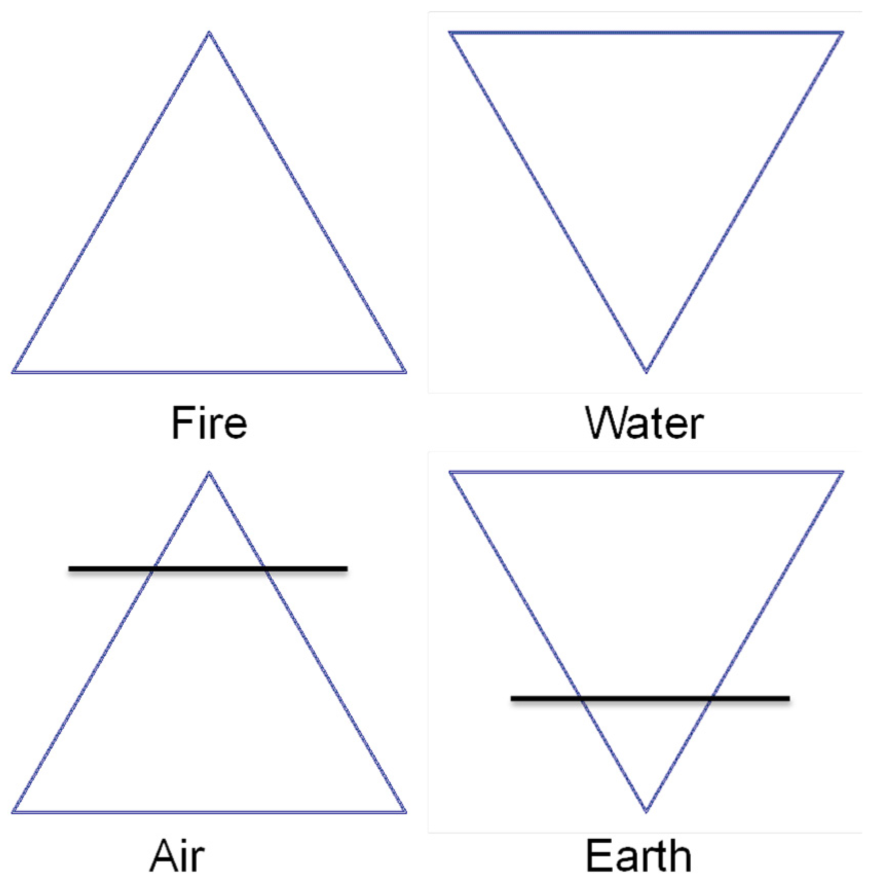
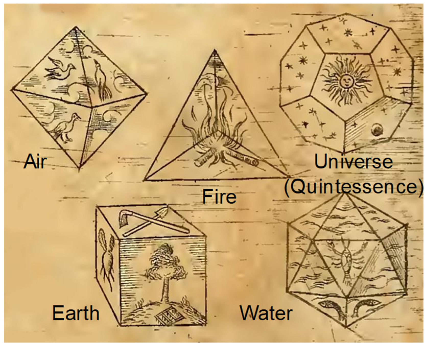
2.1. Plato
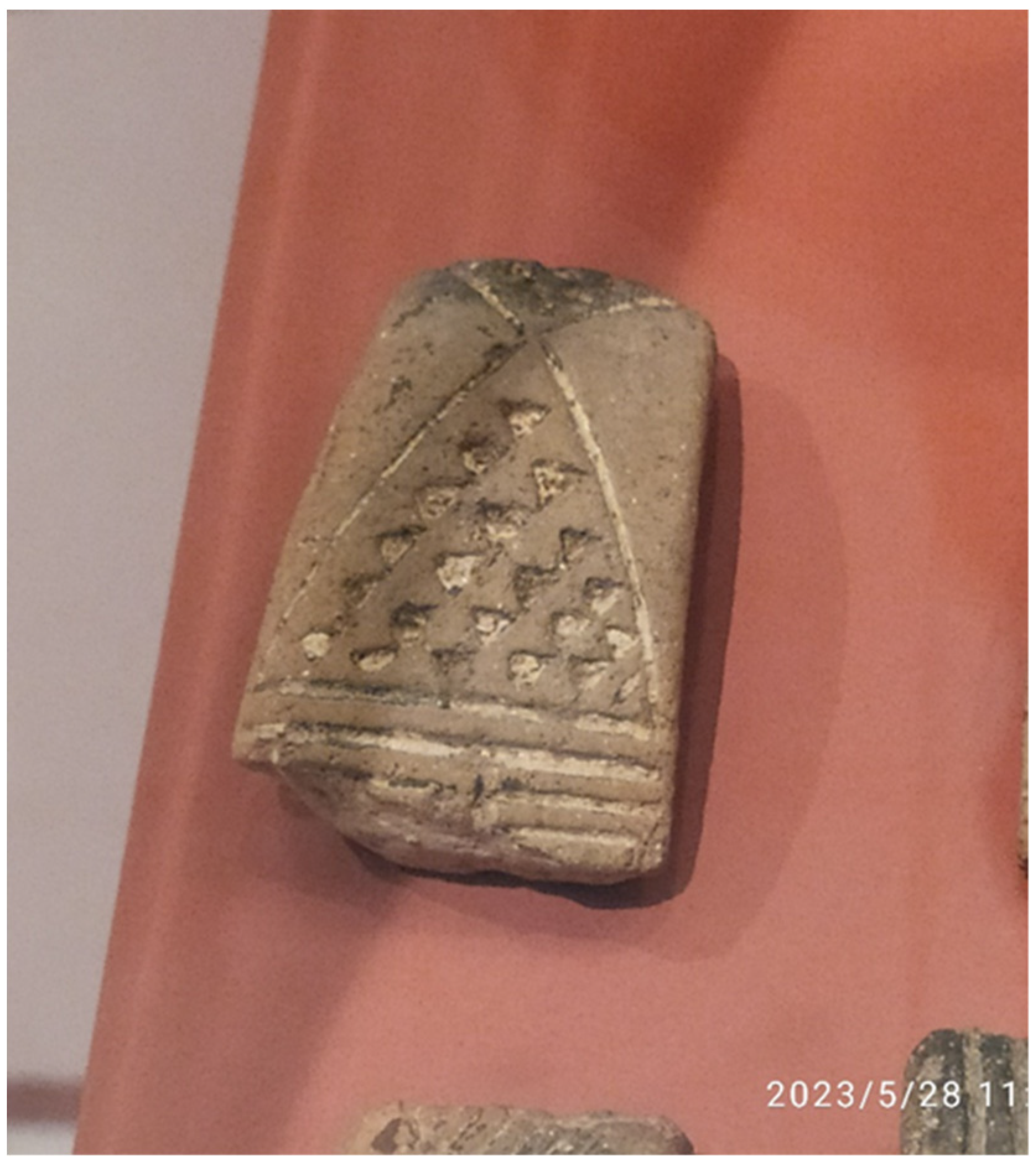
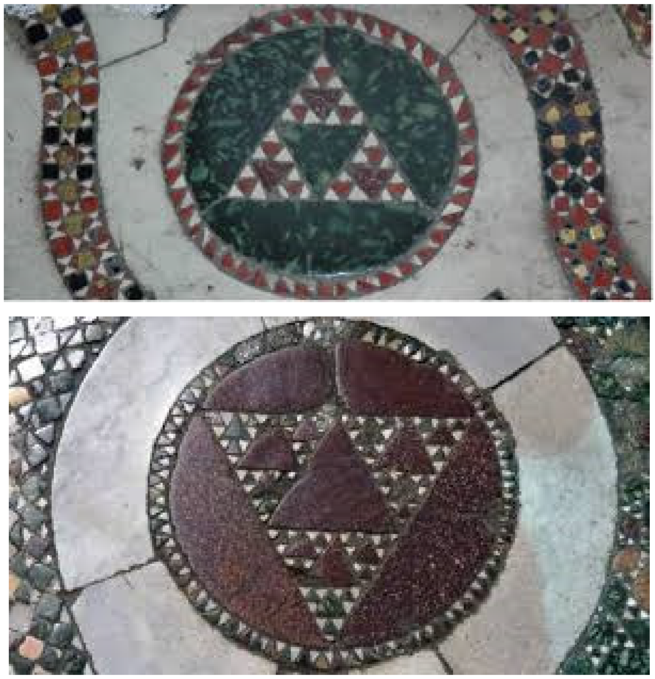
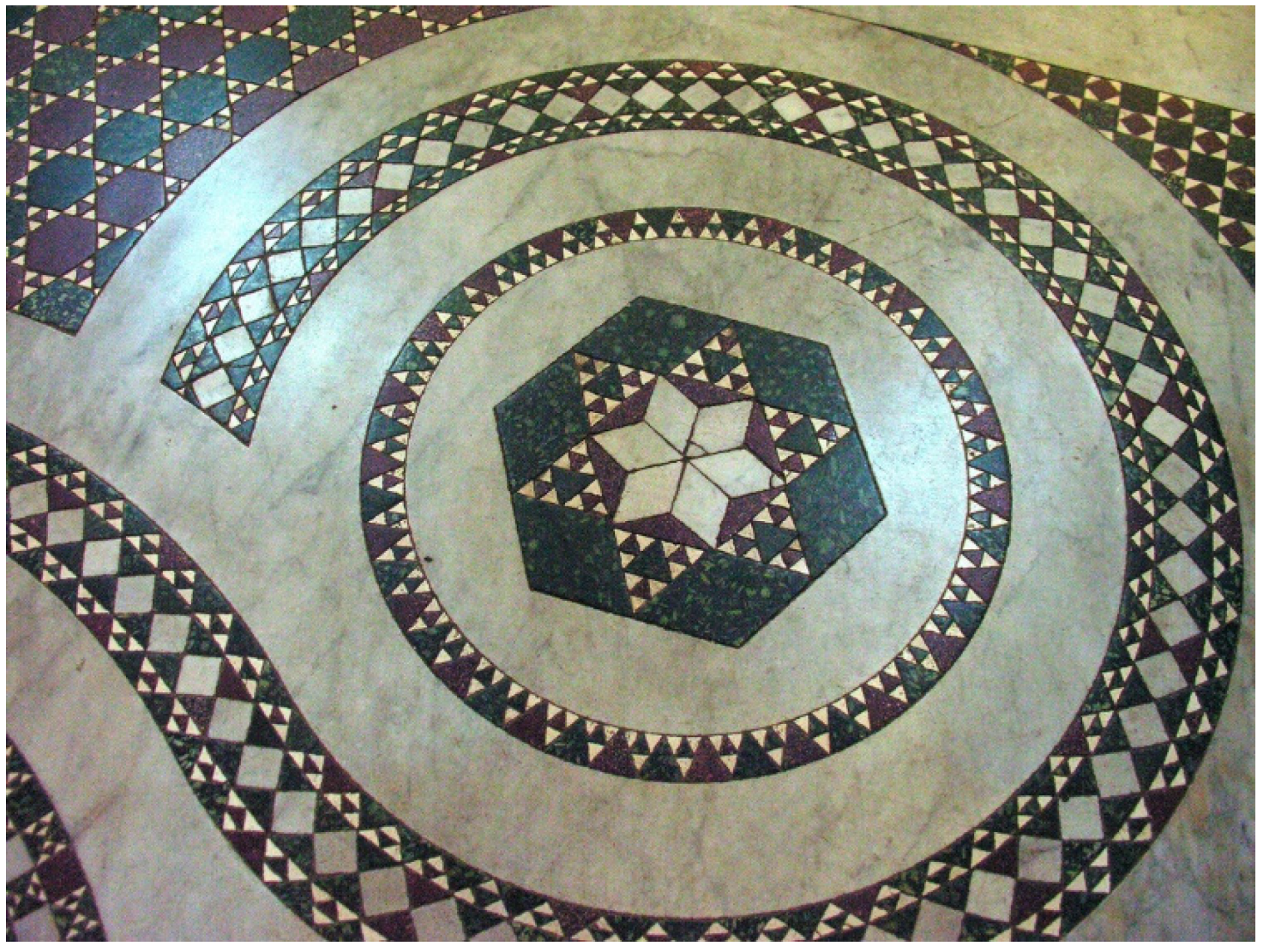
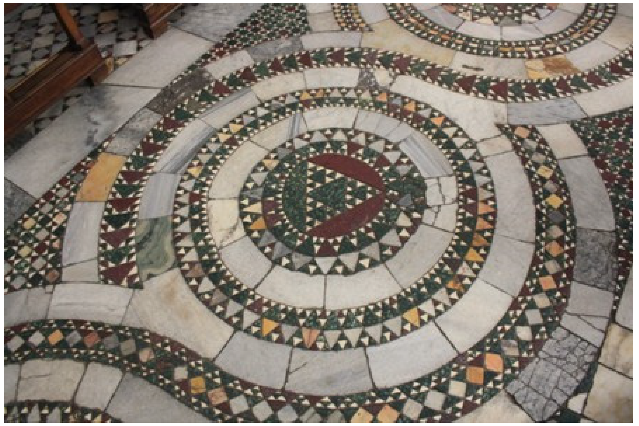
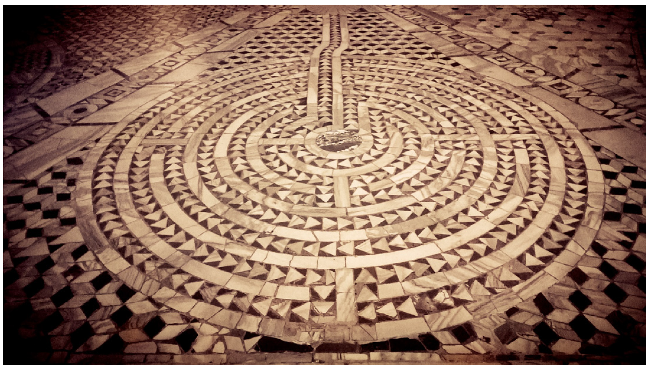
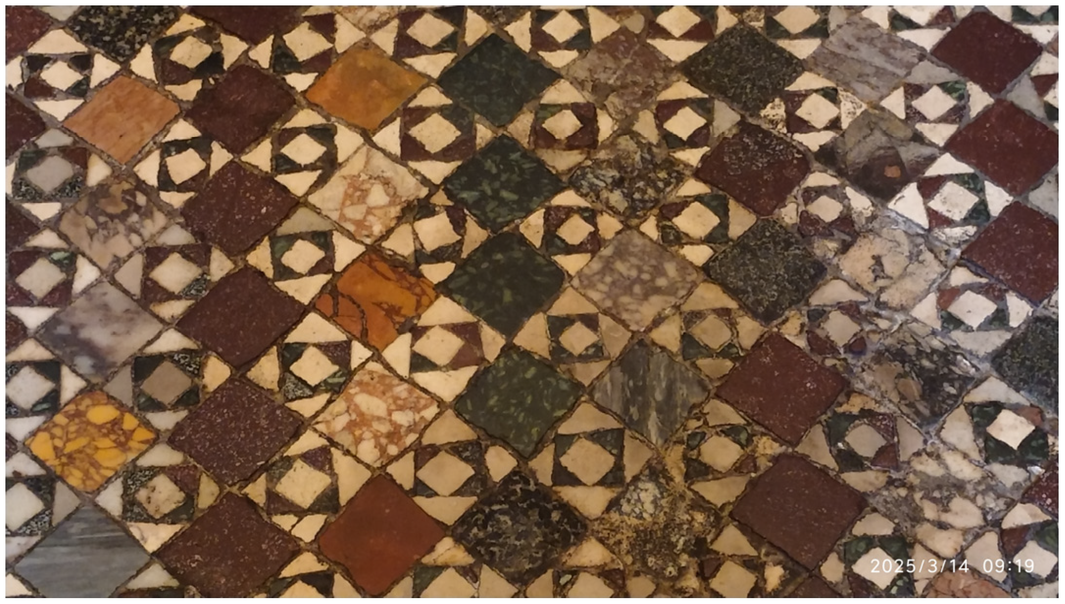
2.2. Ancient Art and Cosmatesque Decorations
2.3. Other Cultural Environments Using Triangles
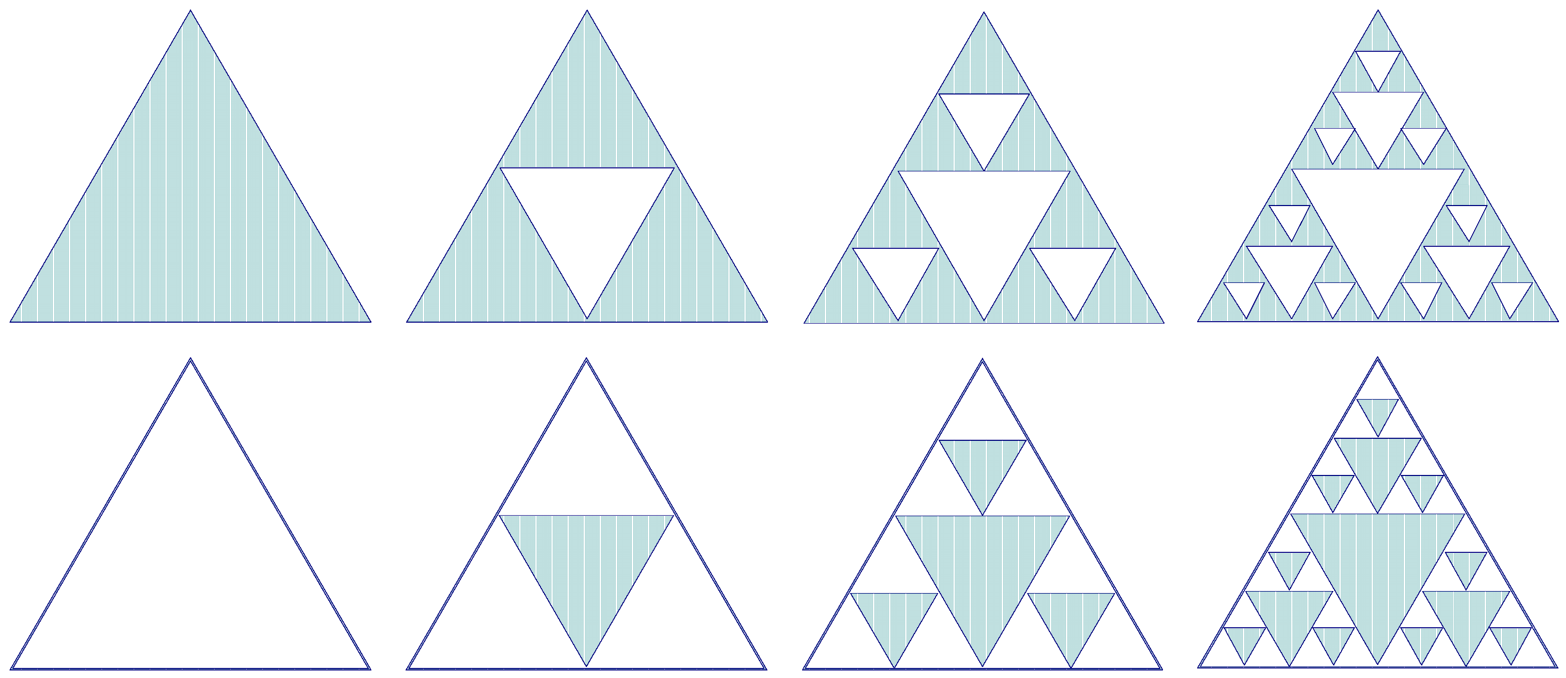
3. Mathematics and Geometry of Sierpiński Fractals
4. High-Frequency Applications
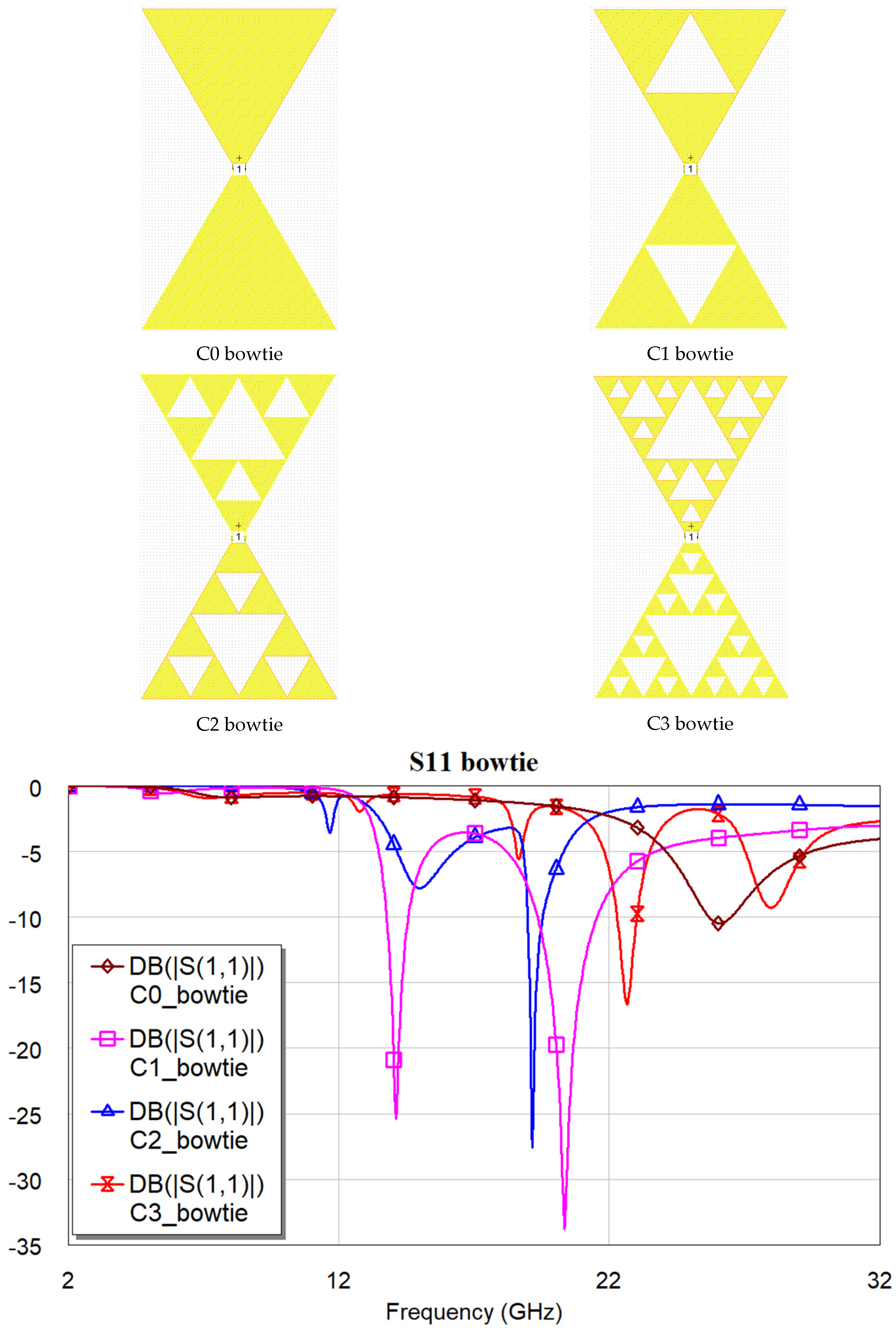
4.1. Resonance Frequencies
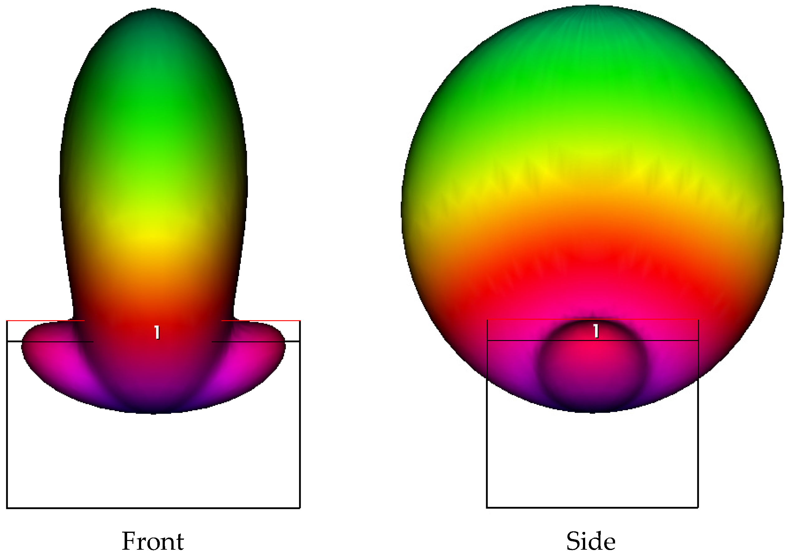
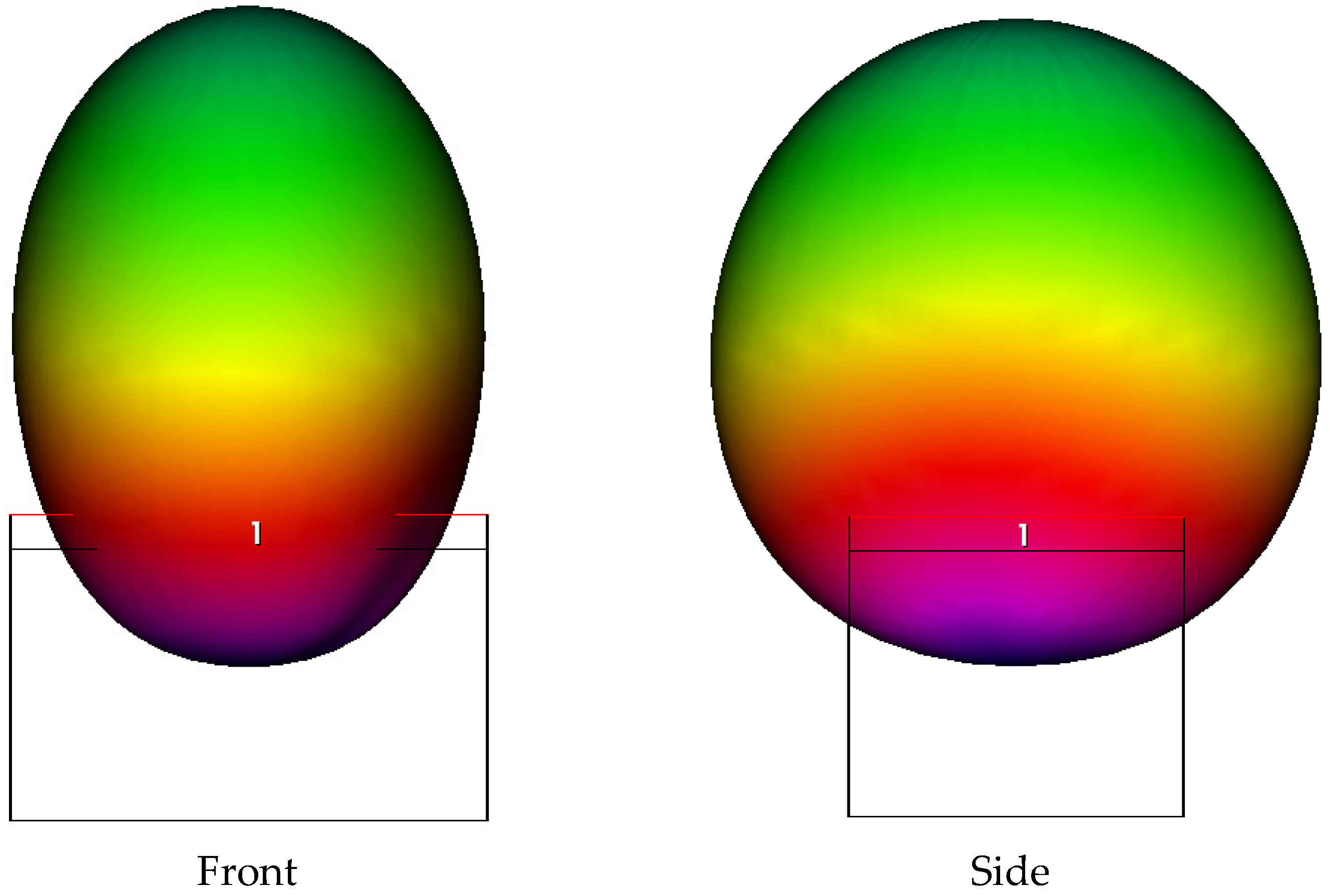
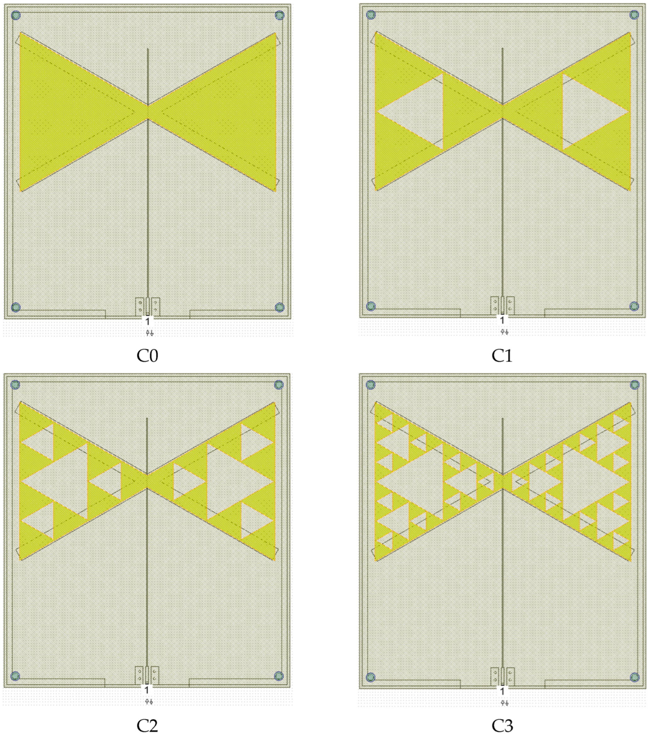
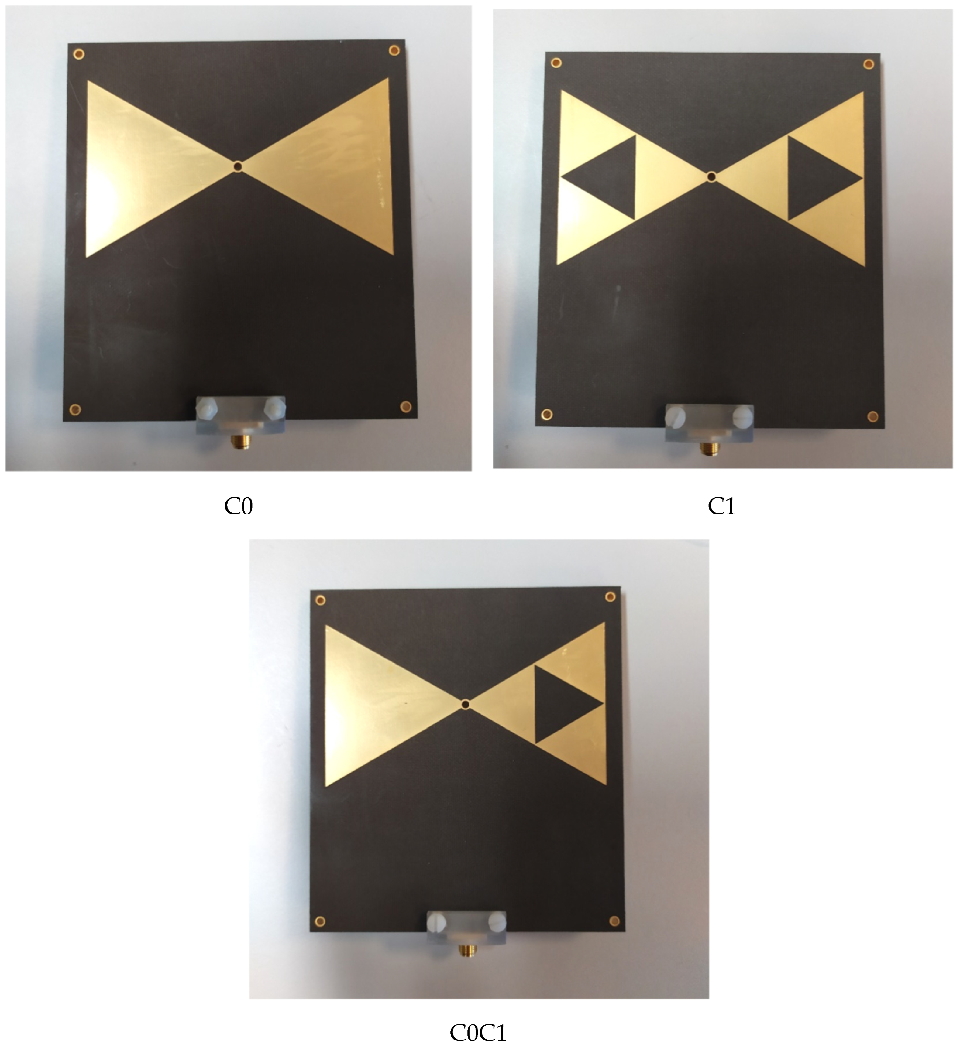
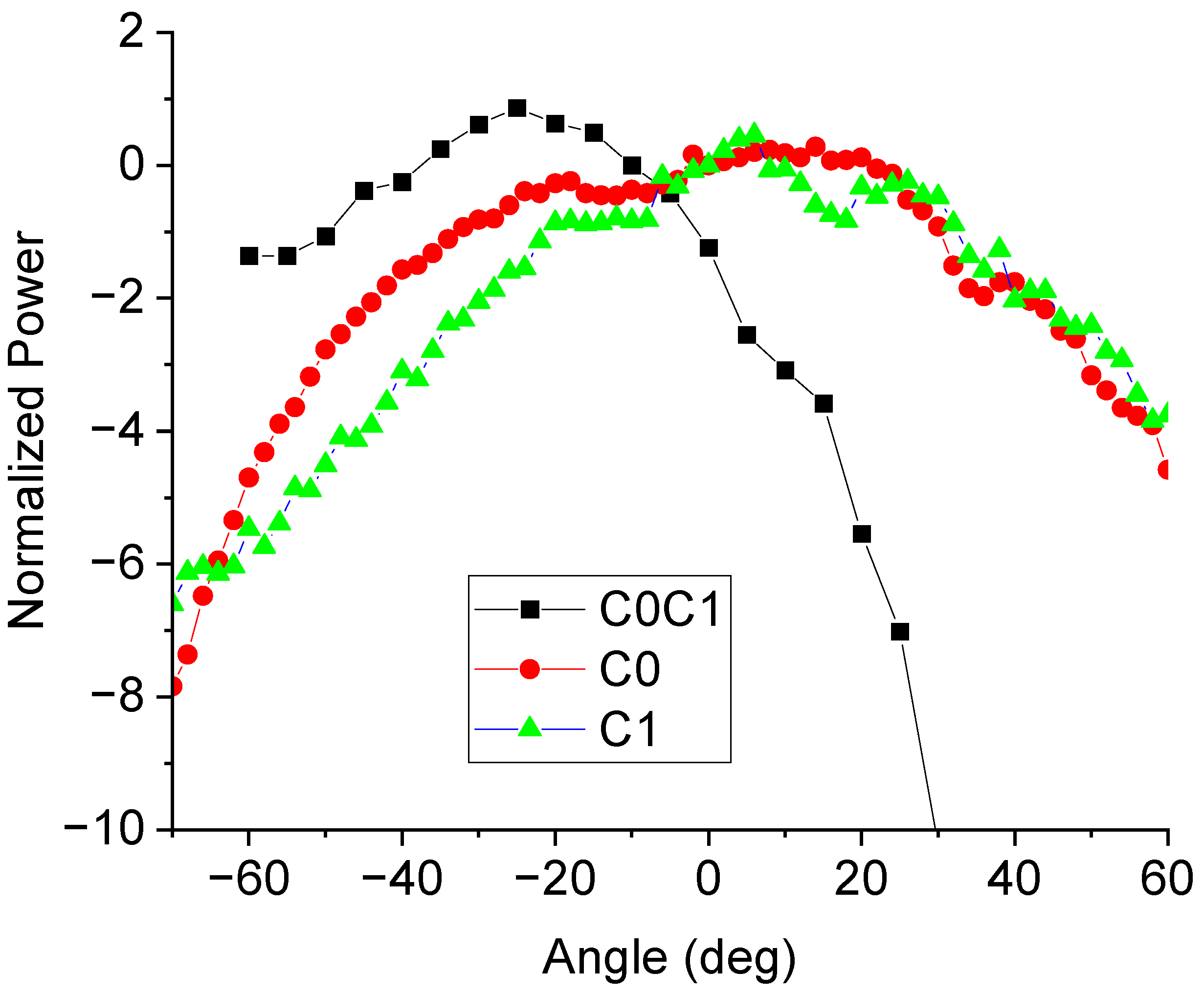
4.2. Antennas
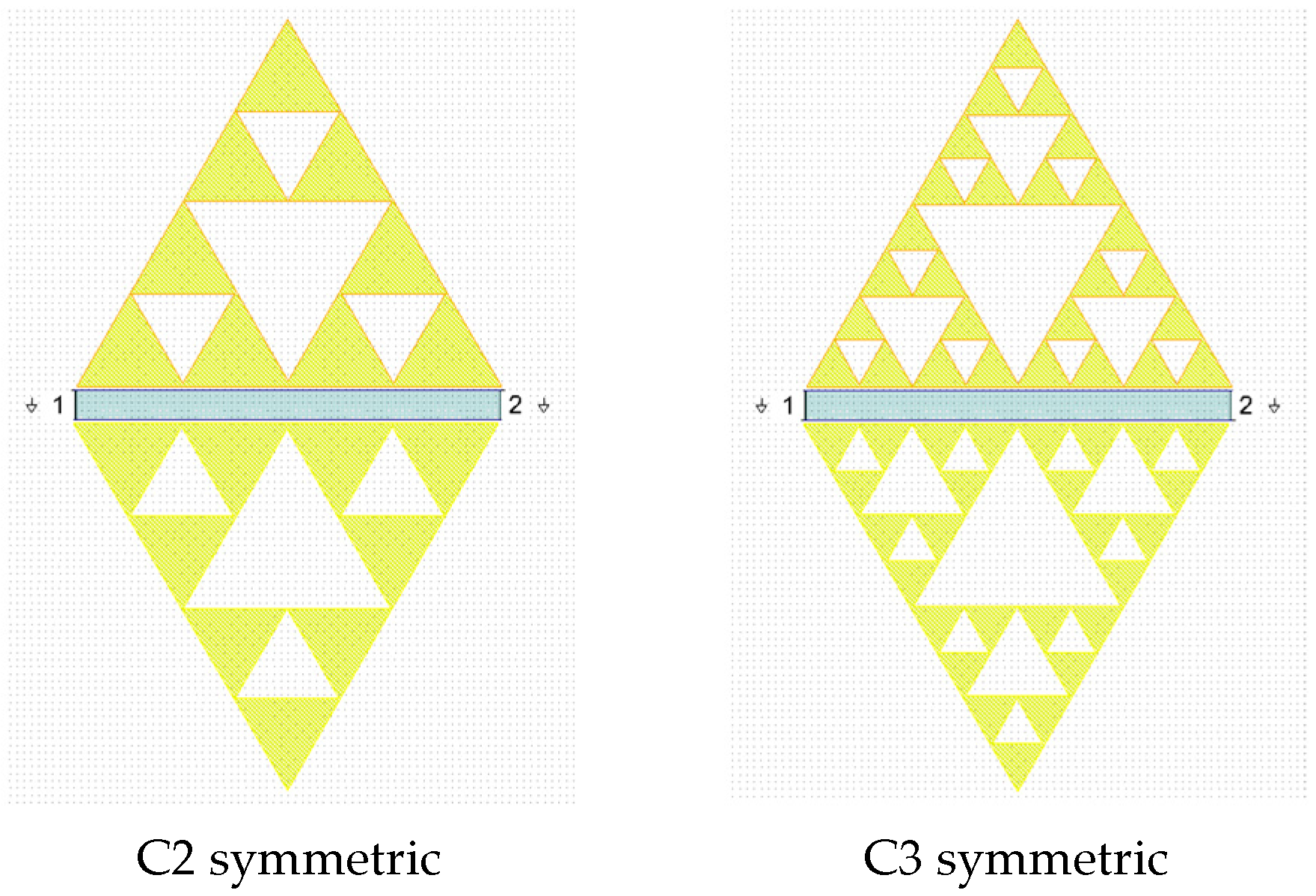
4.3. Resonators
4.4. Further Considerations, Limitations, and Future Work for Microwave Applications
5. Conclusions
Funding
Data Availability Statement
Acknowledgments
Conflicts of Interest
References
- The Editors of Encyclopaedia Britannica. Pythagorean theorem. In Encyclopedia Britannica; Britannica: Chicago, IL, USA, 2024; Available online: https://www.britannica.com/science/Pythagorean-theorem (accessed on 14 June 2024).
- Burgin, M. Platonic Triangles and Fundamental Triads as the Basic Elements of the World. Athens J. Humanit. Arts 2018, 5, 29–44. [Google Scholar] [CrossRef]
- Artmann, B.; Schaefer, L. On Plato’s Fairest Triangles (Timaeus 54a). Hist. Math. 1993, 20, 255–264. [Google Scholar] [CrossRef]
- Lloyd, D.R. Symmetry and Beauty in Plato. Symmetry 2010, 2, 455–465. [Google Scholar] [CrossRef]
- Sierpiński, W. Pythagorean Triangles; Dover Publications Inc.: New York, NY, USA, 2003; Available online: https://www.softouch.on.ca/kb/data/Pythagorean%20Triangles.pdf (accessed on 25 June 2025).
- Stewart, I. Number Symbolism; Encyclopedia Britannica: Chicago, IL, USA, 2024; Available online: https://www.britannica.com/topic/number-symbolism (accessed on 19 June 2024).
- Williams, K. Paloma Pajares-Ayuela—Cosmatesque Ornament: Flat Polychrome Geometric Patterns in Architecture; W.W. Norton: London, UK; New York, NY, USA, 2001. [Google Scholar]
- Rodwell, W.; Neal, D.S. The Cosmatesque Mosaics of Westminster Abbey: The Pavements and Royal Tombs: History, Archaeology, Architecture and Conservation; Oxbow Books: Oxford, UK, 2019. [Google Scholar]
- Severino, N. “COSMATI: La Firma Dell’Artista. I Tratti Inequivocabili Dell’arte Cosmatesca Della Bottega di Lorenzo tra il XII e il XIII Secolo. Alla Scoperta del Repertorio Cosmatesco vero e Definitivo di Lorenzo, Iacopo, Cosma e Figli. Studi sui Pavimenti Cosmateschi,” ilmiolibro.it, Cromografica, Roma, Marzo 2014. Edizione Digitale Libera su Academia.edu. Questa Versione è Stata Corretta e Modificata il 15 Ottobre 2014. (In Italian). Available online: https://www.academia.edu/39870500/COSMATI_La_firma_dellArtista_I_tratti_inequivocabili_dell_arte_cosmatesca_della_bottega_di_Lorenzo_tra_il_XII_e_il_XIII_secolo_Alla_scoperta_del_repertorio_cosmatesco_vero_e_definitivo_di_Lorenzo_Iacopo_Cosma_e_Figli (accessed on 25 June 2025).
- Mandelbrot, B.B. The Fractal Geometry of Nature; Henry Holt and Company: New York, NY, USA, 1983; ISBN 0716711869/9780716711865. [Google Scholar]
- Falconer, K. Fractal Geometry: Mathematical Foundations and Applications; John Wiley & Sons: Hoboken, NJ, USA, 2003; ISBN 978-0-470-84862-3. [Google Scholar]
- Sierpiński, W. Sur une courbe dont tout point est un point de ramification. Comptes Rendus Acad. Sci. Paris 1915, 160, 302–305. [Google Scholar]
- Bickle, A. Properties of Sierpiński Triangle Graphs. In Combinatorics, Graph Theory and Computing; SEICCGTC 2021; Hoffman, F., Holliday, S., Rosen, Z., Shahrokhi, F., Wierman, J., Eds.; Springer Proceedings in Mathematics & Statistics; Springer: Cham, Switzerland, 2024; Volume 448. [Google Scholar] [CrossRef]
- Sun, Q.; Cai, L.; Ma, H.; Yuan, C.; Xu, W. On-surface construction of a metal–organic Sierpiński triangle. Chem. Commun. 2015, 51, 14164. [Google Scholar] [CrossRef]
- Available online: https://it.mathworks.com/matlabcentral/fileexchange/158786-Sierpiński-triangle-generator (accessed on 7 July 2024).
- Available online: https://download.cnet.com/Sierpiński-triangle/3000-18498_4-75864275.html?ex=RAMP-2070.4 (accessed on 7 July 2024).
- Available online: https://www.comsol.it/multiphysics/finite-element-method (accessed on 7 July 2024).
- Guo, S.; Chen, W.; Wang, H.; Qiu, Z.; Wei, B.; Cheng, J.; Yuan, H.; Zhou, Y.; Luo, H. Simulation and experimental research on the cavitation phenomenon of wedge-shaped triangular texture on the surface of 3D-printed titanium alloy materials. Tribol. Int. 2024, 198, 109869. [Google Scholar] [CrossRef]
- Mishra, G.P.; Maharana, M.S.; Modak, S.; Mangaraj, B.B. Study of Sierpiński Fractal Antenna and Its Array with Different Patch Geometries for Short Wave Ka Band Wireless Applications. Procedia Comput. Sci. 2017, 115, 123–134. [Google Scholar] [CrossRef]
- Marcelli, R.; Capoccia, G.; Sardi, G.M.; Bartolucci, G.; Margesin, B.; Iannacci, J.; Tagliapietra, G.; Giacomozzi, F.; Proietti, E. Metamaterials based RF microsystems for telecommunication applications. Ceram. Int. 2023, 49 Pt B, 24379–24389. [Google Scholar] [CrossRef]
- Available online: https://en.wikipedia.org/wiki/Philosopher%27s_stone (accessed on 14 March 2025).
- Goodrick-Clarke, N., Translator; Paracelsus: Essential Readings, North Atlantic Books: Berkeley, CA, USA, 1999.
- Shirts, M.R.; Mobley, D.L.; Chodera, J.D. Chapter 4 Alchemical Free Energy Calculations: Ready for Prime Time? Spellmeyer, D.C., Wheeler, R., Eds.; Annual Reports in Computational Chemistry; Elsevier: Amsterdam, The Netherlands, 2007; Volume 3, pp. 41–59. ISSN 1574-1400. ISBN 9780444530882. Available online: https://www.sciencedirect.com/science/article/pii/S1574140007030046 (accessed on 25 June 2025). [CrossRef]
- Khuttan, S.; Azimi, S.; Wu, J.Z.; Gallicchio, E. Alchemical Transformations for Concerted Hydration Free Energy Estimation with Explicit Solvation. arXiv 2005, arXiv:2005.06504. [Google Scholar] [CrossRef]
- Holmyard, E.J. Alchemy; Dover Publication: New York, NY, USA, 1990; ISBN 10 0486262987. Originally published: Penguin, Harmondsworth, Middlesex, UK, 1957. [Google Scholar]
- Plato. Timaeus; Kalkavage, P., Translator; Focus Publishing/R Pullins & Co.: Newburyport, MA, USA, 2016. [Google Scholar]
- Herrmann, D. Ancient Mathematics—History of Mathematics in Ancient Greece and Hellenism; Springer: Berlin/Heidelberg, Germany, 2023; ISBN 978-3-662-66493-3/978-3-662-66494-0. [Google Scholar] [CrossRef]
- Kepler, J. 1571–1630; “Harmonices Mundi”, Ptolemy, 2nd cent; Fludd, Robert, 1574-1637; Tambach, Gottfried, fl. 1607–1632, Publisher; Planck, Johann, fl. 1615–1627, Printer; Burndy Library, Donor. DSI. Available online: https://archive.org/details/ioanniskepplerih00kepl/mode/2up (accessed on 25 June 2025).
- Emmer, M. Art and Mathematics: The Platonic Solids. Leonardo 1982, 15, 277–282. Available online: https://muse.jhu.edu/article/600238 (accessed on 25 June 2025). [CrossRef]
- Huylebrouck, D. Dark and Bright Mathematics: Hidden Harmony in Art, History and Culture; Copernicus Books; Birkhäuser: Basel, Switzerland, 2023; ISBN 978-3-031-36254-5/978-3-031-36255-2. [Google Scholar] [CrossRef]
- Kalvesmaki, J. The Theology of Arithmetic: Number Symbolism in Platonism and Early Christianity; Hellenic Studies Series 59; Center for Hellenic Studies: Washington, DC, USA, 2013; Available online: http://nrs.harvard.edu/urn-3:hul.ebook:CHS_KalvesmakiJ.The_Theology_of_Arithmetic.2013 (accessed on 25 June 2025).
- Cirlot, J.E. A Dictionary of Symbols: Revised and Expanded Edition, 1st ed.; Sage, J.; Miles, V., Translators; Victoria Cirlot (Afterword), Herbert Read (Foreword); NYRB Classics (1963 First Ed., 2020); New York Review of Books: New York, NY, USA, 2020; ISBN 10 1681371979/13 978-1681371979. [Google Scholar]
- Conversano, E.; Lalli, L.T. Sierpiński Triangles in Stone, on Medieval Floors in Rome. Aplimat J. Appl. Math. 2011, 4, 113–122. [Google Scholar]
- Brunori, P.; Magrone, P.; Tedeschini, L.L. Imperial Porphyry and Golden Leaf: Sierpiński Triangle in a Medieval Roman Cloister. In Advances in Intelligent Systems and Computing; Springer International Publishing: Berlin/Heidelberg, Germany, 2018; Volume 809, pp. 595–609. ISBN 9783319955872. [Google Scholar] [CrossRef]
- Available online: https://en.wikipedia.org/wiki/Triangular_theory_of_love (accessed on 25 June 2025).
- Available online: https://www.nationalgeographic.com/science/article/see-a-rare-alignment-of-all-the-planets-in-the-night-sky (accessed on 25 June 2025).
- Available online: https://en.wikipedia.org/wiki/Illusory_contours (accessed on 25 June 2025).
- Alany, R.G.; Tucker, I.G.; Davies, N.M.; Rades, T. Characterizing colloidal structures of pseudoternary phase diagrams formed by oil/water/amphiphile systems. Drug Dev. Ind. Pharm. 2001, 27, 32–38. [Google Scholar] [CrossRef] [PubMed]
- Cheng, Q.; Yin, J.; Wen, J.; Yu, D. Mechanical properties of 3D-printed hierarchical structures based on Sierpiński triangles. Int. J. Mech. Sci. 2023, 247, 108172. Available online: https://www.sciencedirect.com/science/article/pii/S0020740323000747 (accessed on 25 June 2025). [CrossRef]
- Dhaliwal, B.S.; Pattnaik, S.S. Artificial Neural Network Analysis of Sierpiński Gasket Fractal Antenna: A Low Cost Alternative to Experimentation. Adv. Artif. Neural Syst. 2013, 2013, 560969. [Google Scholar] [CrossRef]
- Steemson, K.; Williams, C. Generalised Sierpiński Triangles. arXiv 2018, arXiv:1803.00411. [Google Scholar]
- Gurjar, R.; Upadhyay, D.K.; Kanaujia, B.K.; Kumar, A. A compact modified Sierpiński carpet fractal UWB MIMO antenna with square-shaped funnel-like ground stub. AEU-Int. J. Electron. Commun. 2020, 117, 153126. [Google Scholar] [CrossRef]
- Dahele, J.; Lee, K. On the resonant frequencies of the triangular patch antenna. IEEE Trans. Antennas Propag. 1987, 35, 100–101. [Google Scholar] [CrossRef]
- Marcelli, R.; Sardi, G.M.; Proietti, E.; Capoccia, G.; Iannacci, J.; Tagliapietra, G.; Giacomozzi, F. Triangular Sierpiński Microwave Band-Stop Resonators for K-Band Filtering. Sensors 2023, 23, 8125. [Google Scholar] [CrossRef]
- Mishra, R.K.; Ghatak, R.; Poddar, D.R. Design Formula for Sierpiński Gasket Pre-Fractal Planar-Monopole Antennas [Antenna Designer’s Notebook]. IEEE Antennas Propag. Mag. 2008, 50, 104–107. [Google Scholar] [CrossRef]
- Anuradha, A.P.; Sinha, S.N. Design of Custom-Made Fractal Multi-Band Antennas Using ANN-PSO [Antenna Designer’s Notebook]. IEEE Antennas Propag. Mag. 2011, 53, 94–101. [Google Scholar] [CrossRef]
- Mukherjee, P.; Mukherjee, A.; Chatterjee, K. Artificial Neural Network based Dimension Prediction of Rectangular Microstrip Antenna. J. Inst. Eng. 2022, 103, 1033–1039. [Google Scholar] [CrossRef]
- Kumprasert, N.; Kiranon, W. Simple and accurate formula for the resonant frequency of the equilateral triangular microstrip patch antenna. IEEE Trans. Antennas Propag. 1994, 42, 1178–1179. [Google Scholar] [CrossRef]
- Priya, S.K.; Bhandari, J.K.; Chaitanya, M.K. Design and Research of Rectangular, Circular and Triangular Microstrip Patch Antenna. Int. J. Innov. Technol. Explor. Eng. 2019, 8, 10. [Google Scholar] [CrossRef]
- Cismaru, A.; Giacomozzi, F.; Pasteanu, M.; Marcelli, R. Design Optimization of RF MEMS-Driven Triangular Resonators with Sierpinski Geometry for Dual-Band Applications. Micromachines 2025, 16, 446. [Google Scholar] [CrossRef]
- Guney, K.; Kurt, E. Effective side length formula for resonant frequency of equilateral triangular microstrip antenna. Int. J. Electron. 2016, 103, 261–268. [Google Scholar] [CrossRef]
- Helszajn, J.; James, D.S. Planar Triangular Resonators with Magnetic Walls. IEEE Trans. Microw. Theory Tech. 1978, 26, 95–100. [Google Scholar] [CrossRef]
- Bahl, I.; Barthia, P. Microwave Solid State Circuit Design; John Wiley and Sons: New York, NY, USA, 1988. [Google Scholar]
- Akaiwa, Y. Operation Modes of a Waveguide Y Circulator (Short Papers). IEEE Trans. Microw. Theory Tech. 1974, 22, 954–960, Erratum in IEEE Trans. Microw. Theory Tech. 1979, 27, 709. [Google Scholar] [CrossRef]
- Aldrigo, M.; Cismanu, A.; Dragoman, M.; Iordanescu, S.; Proietti, E.; Sardi, G.M.; Bartolucci, G.; Marcelli, R. Amplitude and Phase Tuning of Microwave Signals in Magnetically Biased Permalloy Structures. IEEE Access 2020, 8, 190843–190854. [Google Scholar] [CrossRef]
- Geiler, M.; Gillette, S.; Shukla, M.; Kulik, P.; Geiler, A.L. Microwave Magnetics and Considerations for Systems Design. IEEE J. Microw. 2021, 1, 438–446. [Google Scholar] [CrossRef]
- Tagantsev, A.K.; Sherman, V.O.; Astafiev, K.F.; Venkatesh, J.; Setter, N. Ferroelectric Materials for Microwave Tunable Applications. J. Electroceramics 2003, 11, 5–66. [Google Scholar] [CrossRef]
- Sotyohadi; Afandi, R.; Hadi, D.R. Design and Bandwidth Optimization on Triangle Patch Microstrip Antenna for WLAN 2.4 GHz. In MATEC Web of Conferences; EDP Science: Les Ulis, France, 2018; Volume 164, p. 01042. [Google Scholar] [CrossRef]
- Patel, K.; Pandav, S.; Behera, S.K. Reconfigurable Fractal Devices. IEEE Microw. Mag. 2024, 25, 41–62. [Google Scholar] [CrossRef]
- Dwivedy, B.; Behera, S.K.; Singh, V.K. A Versatile Triangular Patch Array for Wideband Frequency Alteration with Concurrent Circular Polarization and Pattern Reconfigurability. IEEE Trans. Antennas Propag. 2019, 67, 1640–1649. [Google Scholar] [CrossRef]
- Rogers Corporation. RO5880 Data Sheet. Available online: https://www.rogerscorp.com/-/media/project/rogerscorp/documents/advanced-electronics-solutions/english/data-sheets/rt-duroid-5870---5880-data-sheet.pdf (accessed on 7 July 2024).
- Feng, G.; Qi, T.; Li, M.; Li, J.; Wang, X.-W.; Yang, H.-L. A low-profile broadband crossed-dipole antenna with fractal structure and inverted-L plates. Sci. Rep. 2022, 12, 14960. [Google Scholar] [CrossRef]
- Priya, S.S.; Nalini, S.; Sandhiya, R.; Sneha, S. Performance and Analyze of Cross Dipole Antenna with Parasitic Elements. Int. Res. J. Eng. Technol. 2020, 7, 915–919. [Google Scholar]
- Karunakar, G.; Dinesh, V. Analysis of microstrip triangular fractal antennas for wireless application. Int. J. Innov. Res. Electr. Electron. Instrum. Control. Eng. 2014, 2, 2216–2219. [Google Scholar]
- Marcelli, R. Equivalent Circuits for Microwave Metamaterial Planar Components. Sensors 2024, 24, 2212. [Google Scholar] [CrossRef]
- Marcelli, R. Philosophy, Art, Mathematics, and High-Frequency Applications of Triangular Shapes: From Plato to Sierpiński and beyond. In Proceedings of the 2024 International Semiconductor Conference, Sinaia, Romania, 9–11 October 2024. [Google Scholar] [CrossRef]


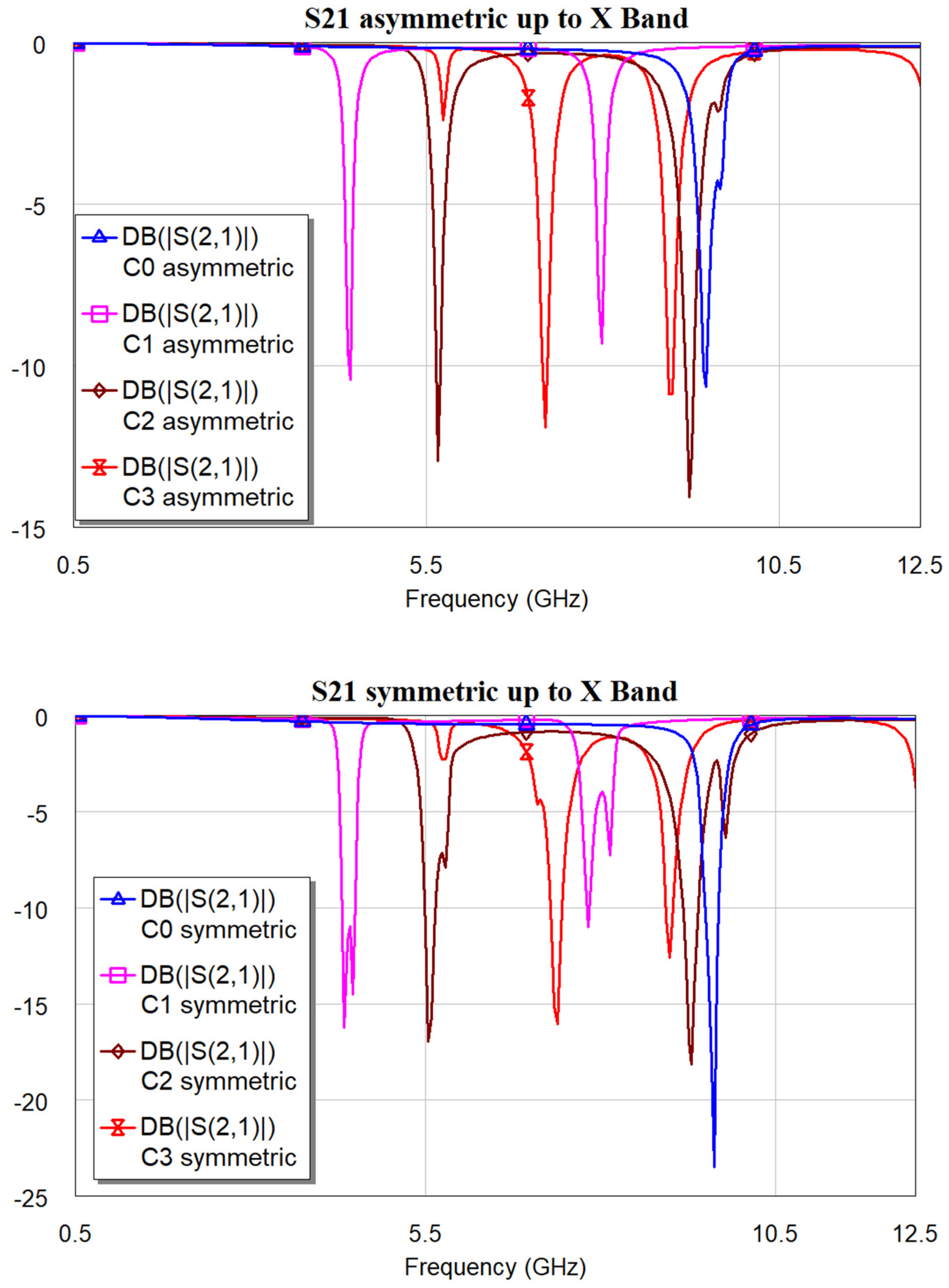
| Resonator | Resonance Frequencies [GHz] | ||
|---|---|---|---|
| Fres1 | Fres2 | Difference | |
| C0 asym | 9.46 | --- | --- |
| C1 asym | 4.42 | 7.98 | 3.56 |
| C2 asym | 5.66 | 9.22 | 3.56 |
| C3 asym | 7.18 | 8.94 | 1.76 |
| C0 sym | 9.62 | --- | --- |
| C1 sym | 4.34 | 7.82 | 3.48 |
| C2 sym | 5.54 | 9.30 | 3.76 |
| C3 sym | 7.38 | 8.98 | 1.60 |
Disclaimer/Publisher’s Note: The statements, opinions and data contained in all publications are solely those of the individual author(s) and contributor(s) and not of MDPI and/or the editor(s). MDPI and/or the editor(s) disclaim responsibility for any injury to people or property resulting from any ideas, methods, instructions or products referred to in the content. |
© 2025 by the author. Licensee MDPI, Basel, Switzerland. This article is an open access article distributed under the terms and conditions of the Creative Commons Attribution (CC BY) license (https://creativecommons.org/licenses/by/4.0/).
Share and Cite
Marcelli, R. A Multidisciplinary Approach to Triangular Shapes: Philosophy, Art, Mathematical Properties, and Application Purposes for High-Frequency Signal Processing Using Sierpiński Geometry. Fractal Fract. 2025, 9, 444. https://doi.org/10.3390/fractalfract9070444
Marcelli R. A Multidisciplinary Approach to Triangular Shapes: Philosophy, Art, Mathematical Properties, and Application Purposes for High-Frequency Signal Processing Using Sierpiński Geometry. Fractal and Fractional. 2025; 9(7):444. https://doi.org/10.3390/fractalfract9070444
Chicago/Turabian StyleMarcelli, Romolo. 2025. "A Multidisciplinary Approach to Triangular Shapes: Philosophy, Art, Mathematical Properties, and Application Purposes for High-Frequency Signal Processing Using Sierpiński Geometry" Fractal and Fractional 9, no. 7: 444. https://doi.org/10.3390/fractalfract9070444
APA StyleMarcelli, R. (2025). A Multidisciplinary Approach to Triangular Shapes: Philosophy, Art, Mathematical Properties, and Application Purposes for High-Frequency Signal Processing Using Sierpiński Geometry. Fractal and Fractional, 9(7), 444. https://doi.org/10.3390/fractalfract9070444