Article

Effects of Different Aggregate Gradations and CO2 Nanobubble Water Concentrations on Mechanical Properties and Damage Behavior of Cemented Backfill Materials

1
School of Mechanics & Civil Engineering, China University of Mining & Technology, Xuzhou 221116, China
2
Laboratory of Rock Engineering & Mining Machinery, Department of Earth Resources Engineering, Kyushu University, Fukuoka 8190395, Japan
3
Sun Yue-qi Honors College, China University of Mining & Technology, Xuzhou 221116, China
*
Author to whom correspondence should be addressed.
Fractal Fract. 2025, 9(4), 217; https://doi.org/10.3390/fractalfract9040217
Submission received: 4 March 2025 / Revised: 25 March 2025 / Accepted: 27 March 2025 / Published: 30 March 2025

Abstract

Against the backdrop of increasingly severe global climate challenges, various industries are in urgent need of developing materials that can both improve performance and reduce carbon emissions. In this study, carbon dioxide nanobubble water (CO2NBW) was evaluated as an innovative additive for cemented backfill materials (CBMs), and its optimization effect on the mechanical properties and microstructure of the materials was explored. The effects of different concentrations of CO2NBW on stress–strain behavior, compressive strength, and microstructure were studied by uniaxial compression tests and scanning electron microscopy (SEM) analysis. The results show that with changes in CO2NBW concentration and fractal dimension, the uniaxial compressive strength (UCS), peak strain, and elastic modulus of the specimens first increase and then decrease. At the optimal concentration level (C = 3) and fractal dimension (2.4150–2.6084), UCS reaches a peak value of 24.88 MPa, which is significantly higher than the initial value (C = 1). The peak strain and elastic modulus also reach maximum values of 0.01231 and 3.005 GPa, respectively. When the fractal dimension was between 2.4150 and 2.6084, the microstructural optimization effect of CO2NBW on CBM was most significant, which was reflected in the compactness of the internal pore structure and the thoroughness of the hydration degree. In addition, based on the close correlation between peak strain and elastic modulus and UCS, a damage constitutive model of CBM specimens considering the influence of CO2NBW concentration and fractal dimension was constructed. The study also found that the damage of CBM specimens is normally distributed with strain, and the accumulated damage in the plastic deformation stage dominates the total damage.

1. Introduction

Cemented backfill materials, in particular, have been a hot topic in the development of mine filling technology as a result of the ongoing improvement of worldwide criteria for sustainable resource usage and environmental protection [1,2]. Cementitious infill products, with their superior physical and chemical characteristics, are essential for stabilizing and restoring the environment in places where mines have closed [3]. This kind of material is often composed of a precise mixture of cement, water, and particles with varying sizes. In addition to provide the required structural support, it also aids in preventing surface collapse and groundwater contamination [4,5]. It is an essential component of a mines’ sustainable development strategy. However, the environmental effect of conventional cementitious filling materials during manufacture and usage has been a study priority because of the growing need for ecologically benign materials. Researchers and industry professionals are concentrating their efforts on maximizing the performance of these materials, particularly in terms of enhancing their environmental performance by lowering energy usage and carbon emissions [6,7,8].
Cemented backfill materials are a type of cement-based materials. One of their primary components, cement, finds extensive application in the domains of civil engineering and mining [9,10]. Although cement is produced in large quantities worldwide, its production process involves considerable energy consumption and CO2 emissions, which has garnered significant attention [11]. Data show that CO2 emissions from the cement sector make up between 5% and 8% of all carbon emissions worldwide, which has a significant effect on how strongly the global greenhouse effect intensifies [12]. Many academics and research organizations, both domestically and internationally, are investigating ways to lessen the carbon footprint of cement-based products by altering the ratio of raw materials, utilizing substitute materials, or introducing new active ingredients in order to lessen this impact [13,14,15]. The use of CO2 nanobubble water offers a creative alternative in this context. It has been demonstrated that nanobubble water technology enhances material performance in a variety of industrial applications. Because of its extremely small bubble diameter and high surface area to volume ratio, nanobubble water may create very little air pressure inside the material, increasing its strength and density [16,17,18]. In addition to this external modification mechanism, the microstructural characteristics of the material itself also play a key role in the mechanical properties and crack formation behavior. Studies have shown that grain size, grain boundary characteristics, and the presence of inclusions will significantly affect the local distribution of stress, crack initiation location, and its propagation path in cement-based materials. For example, Eik et al. [19] observed, using phase contrast tomography, that the grain boundary region often exhibits a high porosity and a concentrated distribution of unhydrated particles, becoming a potential weak interface region, affecting the interface strength and crack propagation resistance. In addition, the numerical simulation results of the hydration process of tricalcium silicate (C3S) by Bullard et al. [20] showed that the deposition pattern and reaction kinetics of the product near the grain boundary have a decisive role in the final microstructural evolution, thereby indirectly regulating the macroscopic properties and destructive behavior of the material. These microstructural factors may work together with the pore regulation induced by nanobubbles and the generation behavior of hydration products to form a synergistic strengthening mechanism. Therefore, when exploring the mechanism of action of CO2 nanobubbles, combining the microstructural perspective can provide a more comprehensive theoretical basis for understanding the damage evolution and performance optimization of cementitious filling materials. Furthermore, the inclusion of CO2 nanobubble water facilitates the uptake of CO2 in filling materials, contributing positively to the decrease of carbon emissions. While carbonization is commonly thought of as a factor that degrades material performance [21,22], recent studies have shown that mild carbonization can somewhat increase a material’s initial strength [23] and may create new opportunities for the development of environmentally friendly material technologies in the future.
Based on the foregoing, this study comprehensively investigated the impacts of CO2 nanobubble water and various aggregate gradations on the mechanical characteristics and damage behavior of cementitious filling materials using uniaxial compression and scanning electron microscopy techniques. This study aims to provide useful technical solutions and a solid scientific foundation for environmental protection and effective resource utilization in industrial applications, in addition to shedding light on the precise mechanism by which CO2 nanobubble water affects the microstructure adjustment of materials and the enhancement of their macroscopic mechanical properties.

2. Materials and Methods

2.1. Physical and Chemical Properties of Test Materials

The cemented backfill material used in this experiment, like most cement-based materials, primarily comprises gel materials (cement), aggregate (quartz sand), and mixing water (CO2NBW). The cement used is ordinary Portland cement with a strength grade of 42.5, and the aggregate consists of high-purity quartz sand particles, with densities of 3.06 g/cm3 and 2.64 g/cm3, respectively. The particle size distribution of the cement significantly impacts the hydration efficiency and strength of cement-based materials; therefore, a laser particle size analyzer was employed to test the cement, with the results shown in Figure 1a. The mixing water, CO2NBW, is produced by a micro-nano bubble generator (model ZJC-NM-200L) from Zhongjing Environmental Technology Co., Ltd., Shanghai, China. Figure 1b presents the nanoparticle tracking analysis data provided by the manufacturer, indicating that the overall size of the bubbles is below 90 nm. Nanobubbles in water possess unique physical and chemical properties, including high stability and a large surface area to volume ratio [24]. The working principle of the equipment involves generating high shear forces through a vortex generator, where pressurized water and gas in the mixing chamber are refined into nano-sized bubbles dissolved in water.
The composition of the raw materials in the cementitious filling material is crucial for determining the material’s strength and long-term stability. Therefore, X-ray diffraction (XRD) analysis was conducted on the cement and quartz sand aggregate, with the results presented in Table 1 and Figure 2. The analysis reveals that the cement primarily contains calcium silicate minerals and aluminosilicate minerals, which can undergo efficient hydration reactions to enhance the long-term strength of the cementitious filling material. Additionally, the quartz sand is predominantly composed of SiO2, indicating its high stability and strength.

2.2. Preparation of CBM Samples

In this study, standard cylindrical specimens with a diameter-to-height ratio of 1:2 (ϕ50 mm × 100 mm) were selected. As the primary raw material for CBM, particle gradation is a critical parameter for the aggregate. Considering the local effects induced by particle size [25], the aggregate particles used in this study were all below 8 mm in diameter. The particle size ranges included 1–2 mm, 2–3 mm, 3–4 mm, 4–5 mm, 5–6 mm, 6–7 mm, and 7–8 mm. Based on the fractal theory shown in Equations (1) and (2) [26], four different fractal dimensions of aggregate particle gradations were chosen. The final calculation results are presented in Figure 3 and Table 2.
P i = M i M t = d i 3 D d min 3 D d max 3 D d min 3 D
where D represents the fractal dimension; di is the pore diameter; dmin is the minimum particle size of the aggregate; dmax is the maximum particle size of the aggregate; Mi is the mass of particles between di and dmax; Mt is the total mass of the particles; and Pi is the mass fraction of the particle size distribution within the specified range.
Notably, when the maximum particle size is significantly larger than the minimum particle size, this approaches 0. Thus, the above equation can be simplified to the following:
P i = M i M t = ( d i d max ) 3 D
Based on previous studies and preliminary laboratory tests, the water-to-cement ratio for CBM was set at 0.6. To investigate the effect of CO2NBW concentration on CBM, the concentration was adjusted by varying the CO2 intake rate. Four different intake rates were selected for this study, 0 L/min, 50 L/min, 100 L/min, and 200 L/min, corresponding to CO2NBW concentration levels of 1, 2, 3, and 4, respectively. Previous research has shown that the internal structure of cement-based materials stabilizes and their mechanical strength approaches its peak after 28 days of curing. Therefore, the curing time for all specimens in this study was set to 28 days. After this period, the specimens were prepared according to the experimental protocol shown in Table 3, with the raw material mixing time set to 10 min, vibration compaction time to 5 min, resting time before demolding to 24 h, and curing temperature and humidity set to 20 ± 2 °C and 95%, respectively.

2.3. Preparation of CBM Samples

To determine the mechanical properties and microstructure changes of the CBM specimens, uniaxial compression tests and microstructure scanning were conducted. The uniaxial compression tests were performed using a WDW-300 testing machine system based on the displacement method, with a sampling interval of 0.1 s, an initial preload of 0.2 kN, and an axial loading rate of 1 mm/min. The microstructure scanning tests were conducted using a TENCAN VEGA COMPACT tungsten filament scanning electron microscope system produced by the Czech TENCAN Group, which has a magnification range of 6x to 1,000,000×. For the observation of the microstructure of the CBM specimens, the tests were performed in high vacuum mode with magnifications of 500× and 2000×.

3. Results

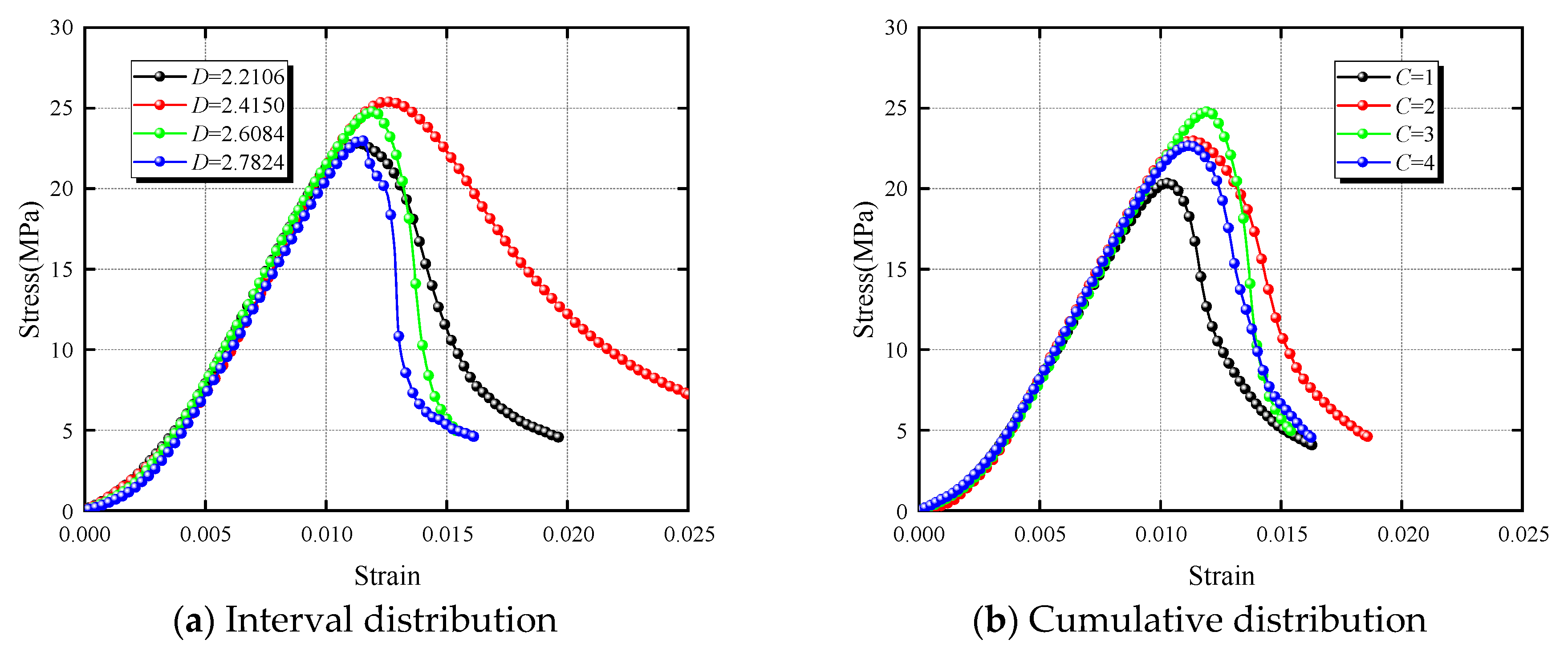
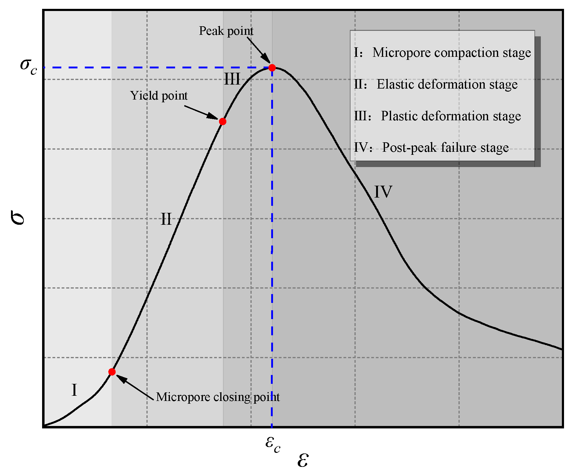
3.1. Analysis of CBM Stress–Strain Behavior Under Different Concentration Levels and Fractal Dimensions

The stress–strain curve provides a clear depiction of the behavior and response of CBM specimens under load. This curve allows us to understand the strain performance of the material under different stress conditions, aiding in the analysis of its elastic, plastic, and fracture behaviors. Figure 4 shows the stress–strain curves of CBM specimens with different fractal dimensions (D = 2.6084) and concentration levels (C = 3). It can be observed that, influenced by the concentration levels and fractal dimensions, the peak stress and peak strain of each curve vary, but the overall trend of the curves is similar. Based on this, the typical stress–strain curve characteristics of CBM specimens, as shown in Figure 5, were summarized. Under vertical load, the deformation of CBM specimens exhibits four typical stages:
I.
Micropore compaction stage: During the sample formation process, micropores and microcracks inevitably exist in CBM specimens. In this stage, the internal micropores and microcracks gradually compress and close, causing the curve to rise concavely from a low slope to a high slope. The proportion and degree of compaction in this stage vary with concentration levels and aggregate gradation.
II.
Elastic deformation stage: In this stage, stress and strain are linearly related, the slope of this stage is the elastic modulus of the sample, and the elastic deformation in this stage can be recovered when unloading. In addition, the end point of this stage is the yield strength, which marks the transition of the material from the reversible elastic state to the irreversible plastic state, and is the critical point where microcracks or local damage begin to appear in the internal structure of the material.
III.
Plastic deformation stage: In this stage, the curve rises from a high slope to a low slope, and a plastic platform appears before reaching the peak. The specimen’s ability to resist deformation decreases, the deformation is irreversible, and macro cracks gradually appear on the surface. The end of this stage corresponds to the peak strength, that is, the maximum stress that the material can withstand, which is a key indicator for measuring its ultimate bearing capacity. After the peak, it enters the destruction stage with rapid strength decay.
IV.
Post-peak failure stage: In this stage, internal microcracks rapidly extend and propagate. Due to friction on both sides of the fracture surface, strain softening occurs during the failure process, allowing the CBM sample to retain some load-bearing capacity even in the failure stage.

3.2. Variation Characteristics of UCS of CBM Under Different Concentration Levels and Fractal Dimensions

Investigating the uniaxial compressive strength (UCS) of cemented backfill materials is vital for enhancing the performance of these materials and plays a critical role in optimizing design and planning. Figure 6 illustrates the variation curves of compressive strength under different concentration levels and fractal dimensions, clearly demonstrating that the compressive strength is highly sensitive to changes in CO2NBW concentrations and aggregate gradations. As depicted in Figure 6a, the UCS trends for CBM specimens remain consistent across various aggregate gradations, with a general increase in strength observed at higher concentration levels. To delve deeper into the effect of concentration levels on the strength characteristics of CBM specimens, the relationship between compressive strength and concentration level was modeled using quadratic polynomial fitting, as detailed in Equation (3). The fitting results are summarized in Table 4. The analysis indicates that the optimal concentration levels for maximum UCS, based on different fractal dimensions, are 2.911, 3.07, 2.857, and 3.451, respectively. Notably, the peak UCS for CBM materials consistently occurs around a concentration level of 3. A comparison of UCS at a baseline concentration level of 1 with higher levels reveals a significant and variable improvement in strength. This suggests that an appropriate increase in CO2NB concentration can markedly enhance the UCS of CBM specimens. However, it is important to consider that CO2NBW consists of both CO2 and NB concentrations. An excessively high CO2 concentration can impair the hydration process within the CBM specimens due to its acidic properties.
σ c = ξ C 1 C 2 + ξ C 2 C + ξ C 3
Among them, ξC1, ξC2, and ξC3 are coefficients related to the concentration level and fractal dimension.
Figure 6b presents the relationship between the UCS of CBM specimens and the fractal dimensions of the aggregate across various concentration levels. Each of the four curves shows a similar pattern: an initial increase followed by a decrease in strength. To elucidate the impact of the fractal dimension on the strength characteristics of CBM specimens, a quadratic polynomial fitting was applied to model the relationship between the UCS and fractal dimension. The fitted equation is provided in Equation (4), and the results are summarized in Table 5. Analysis of these results reveals that the fractal dimension values at which the fitted curves peak at different concentration levels are 2.4888, 2.4804, 2.5036, and 2.5363, respectively. These values align with findings from the related literature [27], indicating that the fractal dimensions for the maximum UCS of CBM specimens fall between 2.4150 and 2.6084. Importantly, there is a gradual increase in the peak fractal dimension values with rising concentration levels.
σ c = ξ D 1 D 2 + ξ D 2 D + ξ D 3
Among them, ξD1, ξD2, and ξD3 are coefficients related to the concentration level and fractal dimension.
The process of specimen formation results from the coupled effects of multiple factors, necessitating further investigation into the evolutionary patterns of UCS under the combined influences of concentration levels and fractal dimensions. To this end, a global polynomial (Poly2D) was utilized to fit the mean compressive strength values, generating the UCS variation surface depicted in Figure 7, influenced by both the concentration levels and fractal dimensions. The functional relationship is formulated in Equation (5). The analysis indicates that the entire UCS fitting surface adopts a convex shape as both the concentration levels and fractal dimensions vary. According to the fitting results from Equation (5), the CBM achieves its maximum UCS of 24.88 MPa at a concentration level of 3.1003 and a fractal dimension of 2.5088. Furthermore, by employing contour lines and color markers to project the fitting surface onto a plane, one can visually discern the variations in compressive strength. Within the most interior region of the contour lines, the UCS variation of CBM specimens stabilizes, ranging between 24.17 MPa and 24.88 MPa. Calculations show that at this point, the ranges for the concentration levels and fractal dimensions span from 2.2424 to 3.9596 and 2.4737 to 2.5505, respectively. Properly aligning concentration levels and fractal dimensions within these ranges is significant for reducing engineering costs and optimizing filling strategies.
σ c = ξ 1 C 2 + ξ 2 D 2 + ξ 3 C D + ξ 4 C + ξ 5 D + ξ 6
Among them, ξ1, ξ2, ξ3, ξ4, ξ5, and ξ6 are coefficients related to the concentration level and fractal dimension.

3.3. Peak Strain Variation Characteristics of CBM Under Different Concentration Levels and Fractal Dimensions

Peak strain is a critical metric that reflects the degree and mode of material deformation under stress. Analyzing peak strain can thus provide insights into the deformation behaviors of CBM specimens. Figure 8 illustrates the variation curves for peak strain under various concentrations and fractal dimensions. The data clearly demonstrate a consistent pattern of change, influenced by different CO2NBW concentrations and aggregate fractal dimensions. Specifically, Figure 8a details the relationship curves between the concentration levels and peak strain across various fractal dimensions, indicating a general increase in peak strain with rising concentration levels. To quantify the relationship between the concentration levels and peak strain, a quadratic polynomial fit was applied, as detailed in Equation (6), with relevant parameters displayed in Table 6. According to the fit, the curves reach their maxima at concentration levels of 3.06, 2.72, 3.29, and 3.89, corresponding to peak strains of 0.01142, 0.01231, 0.0118, and 0.01128, respectively. These results suggest that to maximize the deformation resistance of CBM, CO2NBW concentrations should ideally be maintained around level 3. Additionally, the data reveal that at a fractal dimension of 2.4150, CO2NBW significantly enhances the deformation resistance of CBM specimens.
ε c = ζ C 1 C 2 + ζ C 2 C + ζ C 3
Among them, ζC1, ζC2, and ζC3 are coefficients related to the concentration level and fractal dimension.
Figure 8b presents the relationship between peak strain and fractal dimensions for CBM specimens across different concentration levels. Overall, influenced by the aggregate gradation, the peak strain exhibits a trend of increasing initially and then decreasing. This relationship was modeled using a quadratic polynomial, detailed in Equation (7). The fitting results, summarized in Table 7, indicate the fractal dimensions at which the fitted curves peak for each concentration level, specifically 2.46, 2.48, 2.49, and 2.51, with corresponding peak strains of 1.065, 1.151, 1.251, and 1.159. The data indicate that the peak strains reach their maxima around a fractal dimension of 2.485 across the concentration levels, suggesting that this fractal dimension provides optimal deformation resistance for the CBM specimens.
ε c = ζ D 1 C 2 + ζ D 2 C + ζ D 3
Among them, ζD1, ζD2, and ζD3 are coefficients related to the concentration level and fractal dimension.
Figure 6 and Figure 8 demonstrate that under identical conditions, the trends in the UCS and peak strain for CBM specimens are similar. This indicates that, on a macroscopic level, there is a strong correlation between the load-bearing capacity and deformation resistance of CBM specimens; greater load-bearing capacity is associated with improved deformation resistance. To quantify the relationship between the UCS and peak strain, a fitting analysis was performed on both the measured and mean values, as detailed in Equation (8), with the results shown in Figure 9. The fitting results indicate that both the measured and average values are well represented by a linear function, which substantiates the correlation between the compressible strength and peak strain in CBM specimens.
σ c = ζ 1 ε c + ζ 2
Among them, ζ1 and ζ2 are coefficients related to the concentration level and fractal dimension.

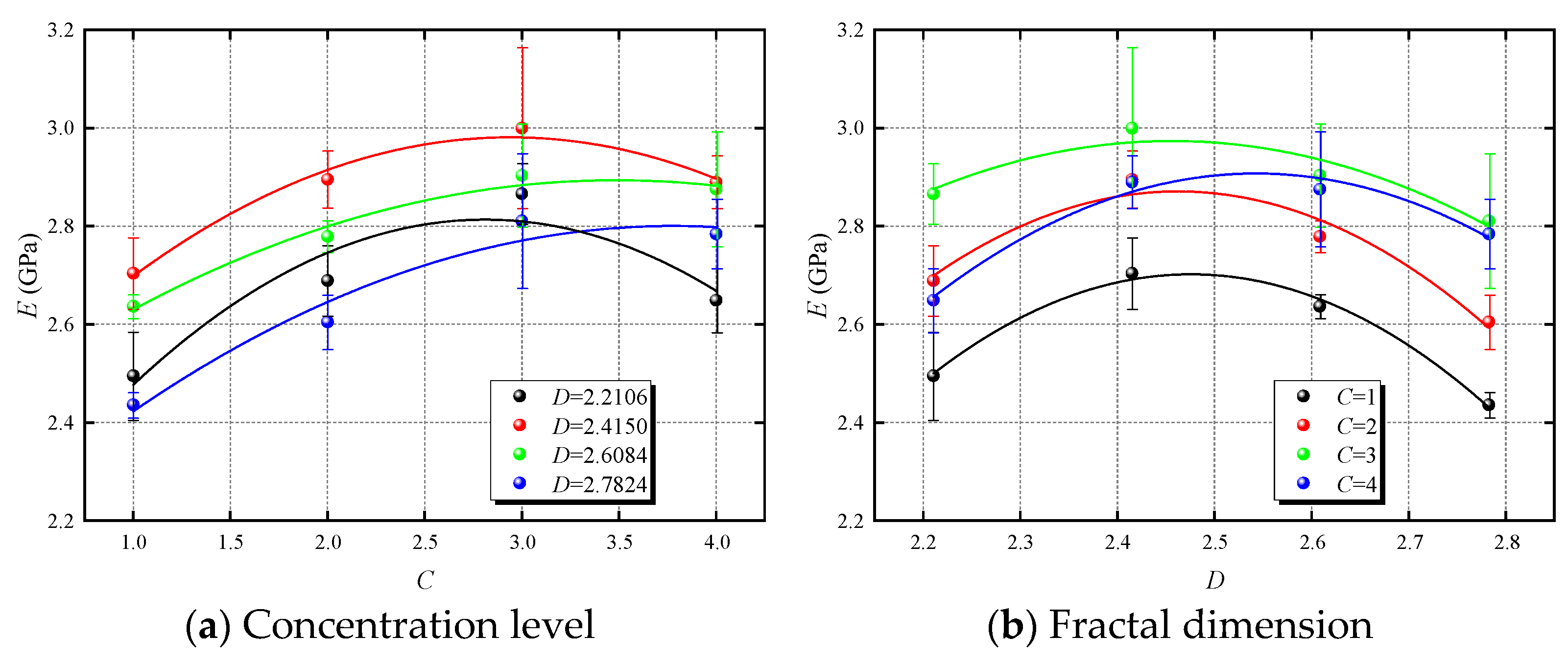
3.4. Variation Characteristics of Elastic Modulus of CBM Under Different Concentration Levels and Fractal Dimensions

The elastic modulus is a crucial physical parameter for evaluating the deformation characteristics of CBM specimens. Figure 10 shows the variation curves of the elastic modulus across different concentration levels and fractal dimensions. As shown in Figure 10a, the elastic modulus exhibits a similar pattern of variation across different concentration levels and fractal dimensions. A quadratic polynomial was used to fit the mean changes in elastic modulus, resulting in Equation (9), which delineates the relationship between the elastic modulus and concentration levels for different fractal dimensions. The fitting results are summarized in Table 8. Influenced by CO2NBW, the elastic modulus of CBM specimens increases to varying degrees across different concentration levels. According to the results from Equation (9), the fitted curves reach their maxima at concentration levels of 2.81, 3.05, 3.49, and 3.78, with corresponding elastic moduli of 2.813 GPa, 3.005 GPa, 2.894 GPa, and 2.8 GPa, respectively. These findings corroborate the trends observed in peak strain, further validating the beneficial role of CO2NBW in enhancing the deformation resistance of CBM specimens.
E = η C 1 C 2 + η C 2 C + η C 3
Among them, ηC1, ηC2, and ηC3 are coefficients related to the concentration level and fractal dimension.
Figure 10b illustrates the relationship between the elastic modulus and fractal dimensions of CBM specimens across various concentration levels. The elastic modulus exhibits a trend of first increasing and then decreasing. A quadratic polynomial, detailed in Equation (10), was used to fit the average elastic modulus values, with the results shown in Table 9. According to Equation (10), the fractal dimensions at which the fitted curves reach their maxima at different concentration levels are 2.48, 2.46, 2.46, and 2.54, with corresponding elastic moduli of 2.7 GPa, 2.87 GPa, 2.97 GPa, and 2.91 GPa, respectively. These findings are consistent with the observed trends in peak strain, indicating that the optimal deformation resistance of CBM specimens occurs around an average fractal dimension of 2.485.
E = η D 1 D 2 + η D 2 D + η D 3
Among them, ηD1, ηD2, and ηD3 are coefficients related to the concentration level and fractal dimension.
The elastic modulus variation, like peak strain, is directly related to the UCS variation. Verifying the correlation between the compressive strength and elastic modulus can aid in predicting changes in the load-bearing capacity of CBM specimens through their elastic properties in future research. As detailed in Equation (11), a fitting analysis was conducted on both the measured and average values of the elastic modulus and compressive strength, with the results presented in Figure 11. The analysis reveals that the elastic modulus, both measured and averaged, correlates well with compressive strength via a linear function. This finding confirms a close relationship between the compressive strength and elastic properties of CBM specimens.
E = η 1 D + η 2
Among them, η1 and η2 are coefficients related to the concentration level and fractal dimension.

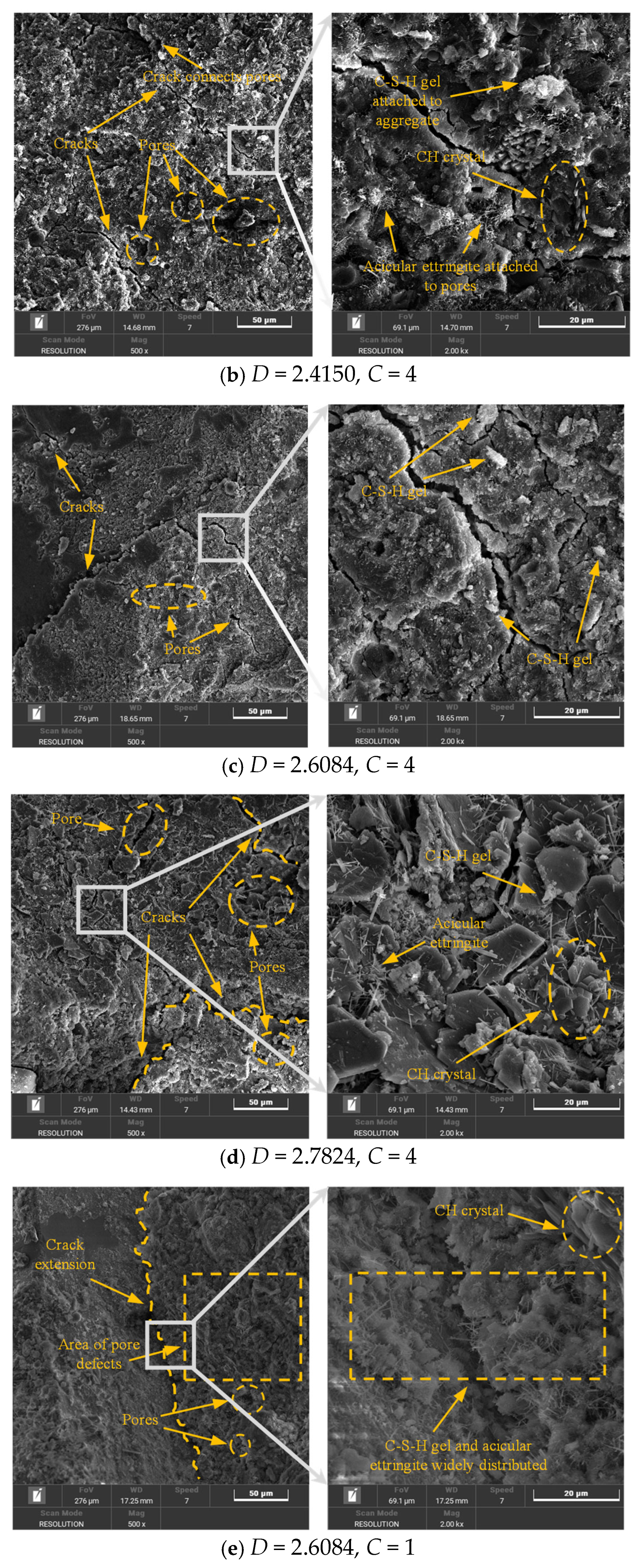
3.5. Microstructural Characteristics

From the above results, it can be seen that the mechanical behavior of CBM samples under different CO2NBW concentrations and aggregate fractal dimensions shows typical four-stage characteristics: micropore compaction, elastic deformation, plastic deformation, and post-peak failure. Further analysis shows that with the increase of the CO2NBW concentration and fractal dimension, the compressive strength (UCS), peak strain, and elastic modulus all show a trend of first increasing and then decreasing, reaching the optimum when the concentration is about 3 and the fractal dimension is 2.4150–2.6084. These macro performance indicators also show good correlation: UCS has a strong linear fitting relationship with the peak strain and elastic modulus, indicating that the bearing capacity and deformation capacity of the material can be synergistically optimized under the control of the above parameters. In order to reveal the microscopic mechanism of this macroscopic performance improvement, it is necessary to further analyze the pore structure and hydration product distribution characteristics of CBM under different parameters. In this section, the microstructure of CBM specimens will be compared and observed by scanning electron microscopy to explore the specific effects of CO2 nanobubbles and aggregate fractal grading on the structural density and hydration reaction at the microscale, thereby clarifying its enhancement mechanism. Figure 12 depicts the microstructural properties of CBM specimens magnified 500 and 2000 times at concentration level 4, as well as the fractal dimension D = 2.6084 at concentration level 1.
Upon magnifying CBM specimens 500 times, it is apparent that the microstructural characteristics vary significantly under the same concentration level across different fractal dimensions. At a fractal dimension of D = 2.2106, the specimen’s internal structure appears relatively loose, characterized by numerous, large microcracks and micropores with high connectivity. As the fractal dimension increases, there is a noticeable decrease in the size and number of micropores and microcracks, alongside a significant reduction in their connectivity. In contrast, at D = 2.7824, the microstructure becomes notably more compact. Compared to D = 2.2106, the microcracks and micropores within the CBM specimens reduce in size but increase in number and are more widely distributed. Hence, these findings suggest that an optimal fractal dimension range of 2.4150 to 2.6084 can effectively enhance the pore structure of CBM specimens. However, dimensions outside this range exhibit varying degradation characteristics: lower fractal dimensions result in larger microcracks and micropores, while higher dimensions lead to greater numbers and wider distribution. Comparison of Figure 12d,e shows that CO2NBW also significantly improves CBM specimens, primarily enhancing the size and connectivity of microcracks and micropores. When specimens are magnified 2000 times, distinct internal hydration phenomena are clearly visible. After 28 days of curing, all CBM specimen treatment plans show substantial hydration progress, with CSH (calcium silicate hydrate) gels, crucial for cement strength, being widely distributed. However, the impact of fractal dimensions is evident. At D = 2.2106, lamellar CH (calcium hydroxide) crystals and numerous acicular ettringite formations are attached to aggregate surfaces and around pores and cracks. As the fractal dimensions increase, both the CH crystals and acicular ettringite decrease, leading to a denser overall surface structure. Conversely, at D = 2.7824, CH crystals and acicular ettringite are prevalent and widely distributed, resulting in a looser surface structure. Comparing Figure 12d,e, the addition of CO2NBW does not lead to a significant reduction in CSH gels or acicular ettringite as might be expected. CH crystals, being less stable and weaker in strength, are a minor component of the hydration products of cement-based materials. Moreover, the strength and degree of hydration of these materials typically peak at around 28 days of curing, with ettringite contributing primarily to early strength. These findings suggest that an optimal fractal dimension range of D = 2.4150–2.6084 results in a densely packed, thoroughly hydrated pore structure in CBM. The addition of CO2NBW significantly enhances the microstructural optimization of CBM specimens, effectively improving the dimensions and depth of the pore structure, and optimizing the hydration process.

4. Loading Damage Constitutive Model of CBM

4.1. Establishment of Constitutive Model

In this test, the internal structure and strength evolution of the CBM specimens showed extremely high sensitivity to the CO2NBW concentration and aggregate grading. Consequently, this study defines the initial damage of CBM specimens based on these observations. Previous findings determined that there is a strong correlation between the strength and elastic modulus of the specimens. Based on this conclusion, a formula for calculating the damage variable of CBM specimens based on their elastic modulus has been established, as presented in Equation (12) [28].
D E c i = 1 E i E 0
In the above equation, DEci represents the damage variable for the i-th CBM specimen, and Ei denotes the elastic modulus of the i-th specimen. Typically, E0 is defined as the undamaged elastic modulus, and the value of the damage variable DEci ranges from 0 to 1. The findings indicate that the CBM specimens from treatment plan C = 3, D = 2.4150 exhibit optimal strength and deformation resistance. For this reason, the elastic modulus at treatment plan C = 3, D = 2.4150 is designated as the undamaged elastic modulus E0.
Considering the loading conditions, the damage variable of the CBM can be modified as follows:
D E = 1 ( 1 D E c ) ( 1 D E m )
In the above equation, DE is the modified damage variable, and DEm is the damage variable considering the load effect.
In equation (13), the loading damage variable can be expressed as shown in Equation (14) [29]:
D E m = 0 ε p ( x ) d x = 1 exp [ ( ε i ε 0 ) m ]
In this equation, εi is the strain, and ε0 and m are distribution parameters.
Substituting Equations (12) and (14) into Equation (13), the damage evolution equation of the CBM can be obtained:
D E = 1 E i E 0 exp [ ( ε i ε 0 ) m ]
Referring to previous studies, the damage constitutive model of CBM can usually be expressed as [30]:
σ = E 0 ( 1 D E ) ε
Substituting Equation (15) into Equation (16), the damage constitutive equation of the CBM after loading can be obtained:
σ i = E i exp [ ( ε i ε 0 ) m ] ε i
According to the changing trend of the stress–strain curve, the constitutive equation needs to meet the following conditions:
ε i = ε c i , σ i = σ c i
σ cn ε 1 | ( σ c , ε c ) = 0
In this equation, εci and σci are the peak strain and peak stress of the i-th specimen, respectively.
Substituting the boundary conditions of Equations (18) and (19) into Equation (17) yields the following result:
m = 1 ln ( σ c i E i ε c i 2 )
ε 0 = ε c i ( 1 m ) 1 m
However, the stress–strain curve of the CBM has significant micropore compaction characteristics. By fitting the stress–strain curve in the compaction stage, it is found that it satisfies the quadratic polynomial characteristics. Therefore, to reduce the error caused by the compaction stage, the correction coefficient shown in Formula (22) is introduced:
f = a ε i
In this equation, a is the shape parameter.
Putting Equation (22) into Equation (17), the final modified damage constitutive equation can be obtained:
σ i = a E i exp [ ( ε i ε 0 ) m ] ε i 2
Similarly, by substituting the boundary condition Equations (18) and (19) into Equation (23), we can obtain the corrected parameters m and ε0:
m = 2 ln ( σ c i a E i ε c i 2 )
ε 0 = ε c i ( 2 m ) 1 m
According to Equations (20), (21), (24), and (25), ε0 is a distribution parameter related to m, which means that there is only one parameter that affects its distribution in the damage constitutive equation. To avoid the correction factor f changing the distribution of the damage constitutive model, the shape parameter a can be obtained:
a = σ c i E i ε c i 2 e ( 2 m )

4.2. Model Validation

Based on the aforementioned conclusions, by substituting the data shown in the table into Equations (20), (25), and (26), the results for the damage constitutive model parameters are presented in Table 10. Subsequently, these parameters were used in Equation (23) to derive the theoretical stress–strain curves for CBM specimens under different treatment plans. Figure 13 compares the experimental curves with the theoretical curves. It can be observed that the trends of the theoretical and experimental curves under different plans are fundamentally similar, each dividing into four stages: micropore compaction, elastic deformation, plastic deformation, and post-peak failure. In the three pre-peak stages, the theoretical curves closely match the experimental curves. However, in the post-peak stage, the theoretical curves are slightly higher than the experimental ones. Additionally, influenced by the boundary conditions specified in Equations (18) and (19), the peak points of the theoretical and experimental curves coincide. Overall, the damage constitutive equation outlined in Equation (23) effectively represents the stress–strain behavior of CBM specimens during the loading process.

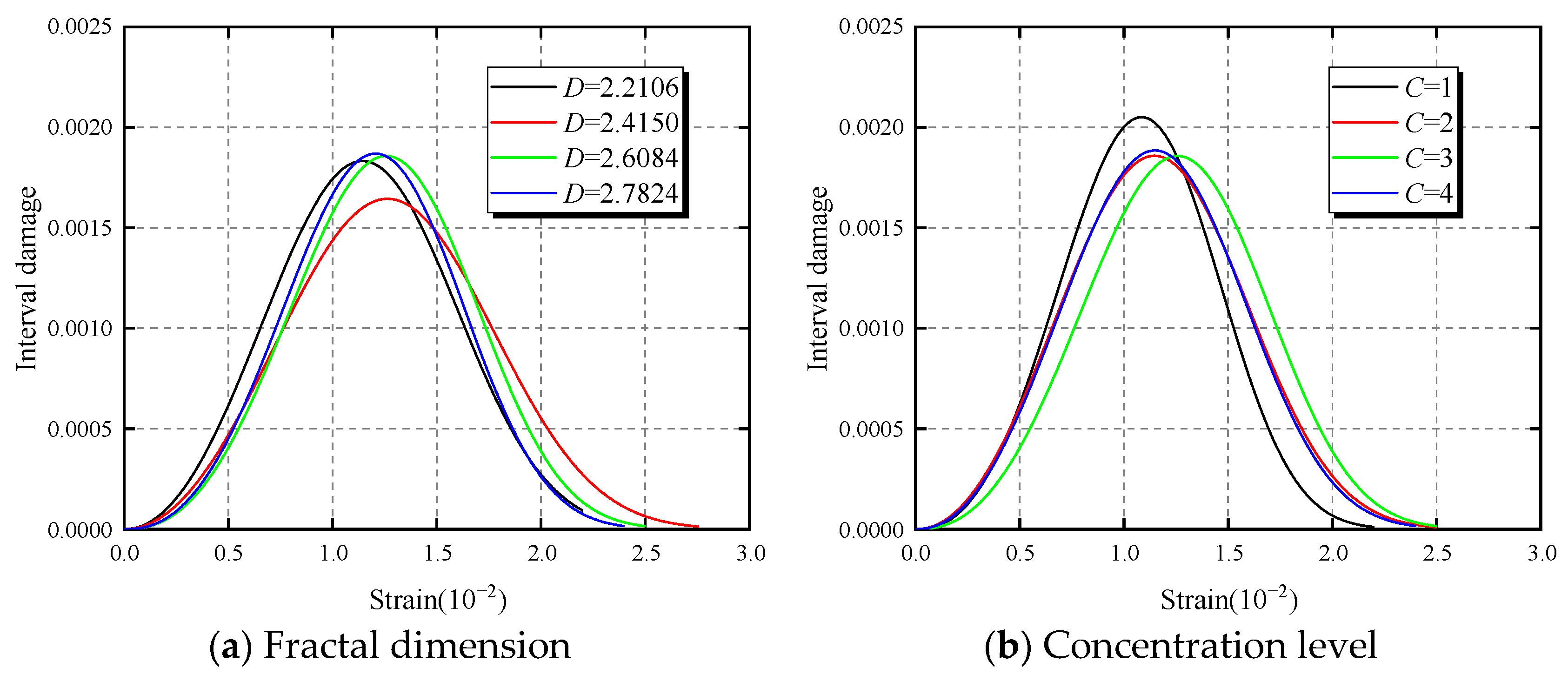
4.3. Damage Evolution Characteristics of CBM

Based on the damage evolution equation shown in Equation (15) and substituting the parameters from Table 10, the damage evolution results for the CBM specimens were obtained. Figure 14 displays the cumulative damage evolution curve for the CBM specimens, showing a consistent S-shaped distribution trend. This characteristic allows for the segmentation of CBM’s cumulative damage into three phases: concave rising, linear rising, and convex rising stages. In this paper, the plan with C = 3, D = 2.4150 is defined as the initial damage state under undamaged conditions. A closer examination of the concave rising phase reveals that the initial damages vary among different plans. Compared to the plan with C = 3, D = 2.4150, the variations in initial damage across different plans correspond with changes in the compressive strength. During the linear rising phase, the cumulative damage increases linearly with strain, with significant damage increments under loading in all plans, accounting for over 60% of the total damage during this stage. The final phase is the convex rising stage, where, comparing with Figure 4, the inflection point of this stage closely aligns with the strain-softening inflection point on the stress–strain curve. Due to residual strength, damage accumulation slows in this phase as the cumulative damage value gradually approaches 1 with increasing strain. Figure 15 shows the interval damage distribution curves for CBM specimens without considering initial damage, revealing a normal distribution trend for interval damage. Additionally, in Figure 15, the damage peaks for each plan align with the strain at the peak points of the stress–strain curves.

5. Discussion and Outlook

This study systematically explored the influence of CO2 nanobubble water (CO2NBW) and aggregate fractal grading on the mechanical properties and microstructure of cementitious backfill materials (CBMs). The results showed that CO2NBW can effectively improve the density and mechanical properties of the material by promoting the hydration reaction and optimizing the pore structure; reasonable control of the aggregate fractal dimension can further enhance the particle packing density and achieve synergistic optimization of the microstructure and macro performance. In addition, the constructed constitutive model can describe the stress–strain evolution process of the material at different loading stages, providing theoretical support for subsequent engineering applications. However, while achieving the above results, it is still necessary to recognize that this study has certain limitations in terms of applicability, feasibility, and long-term performance evaluation, which need to be further expanded and improved in future work.
Although this study uses CBM as the research object and verifies the performance advantages of CO2NBW in this type of material, whether its mechanism of action is also applicable to other types of cement-based materials (such as concrete, grouting materials, etc.) remains to be further verified. In the future, extended research can be carried out in different industry contexts to enrich the material adaptability and engineering application scope of CO2NBW. The research on CO2NBW-modified CBM in this paper mainly focuses on short-term performance within 28 days, and there is still a lack of systematic evaluation of its long-term mechanical stability, durability, and environmental adaptability. In actual underground filling projects, materials need to be in complex environments including humidity, high pressure, and corrosion for a long time. Their strength retention ability, carbonization evolution process, and interface stability are all key factors affecting safe operation. In addition, CBM often coexists with surrounding rocks, pipelines, or other filling materials, and CO2NBW may affect the interface reaction behavior between these materials. Therefore, long-term maintenance and work simulation tests of CBM should be further carried out in the future, and more complete tests and models should be constructed by combining factors such as the CO2 release behavior, structural aging process, microcrack extension, and multi-material contact. This paper only carried out performance tests in laboratory environments and has not yet been verified in actual engineering scenarios. In the future, indoor or field tests will be combined to evaluate the adaptability and stability of CO2 nanobubble water under complex geological conditions to enhance the engineering applicability of the research results. In terms of parameter selection, although the fractal dimension can effectively quantify the aggregate grading characteristics, its application in engineering practice still needs to be simplified. It is recommended to combine the traditional screening analysis method to establish a mapping relationship between the fractal dimension and the conventional grading parameters to improve its understandability and operability in on-site construction. In addition, the damage constitutive model constructed in this paper can effectively describe the stress–strain evolution process of CBM at different loading stages, especially the response characteristics of the four stages of micropore compaction, elastic deformation, plastic yield, and post-peak failure, which provides a theoretical basis for understanding the overall damage process of the material. However, we also realize that the model is still simplified in describing the local damage refinement mechanism, and factors such as the crack tip stress field, microcrack propagation path, and interface weakening have not been fully considered. In existing studies, crack propagation behavior usually requires the introduction of numerical methods such as fracture mechanics models and finite elements to achieve high-precision simulation of crack tip stress concentration, energy release rate, and discontinuous damage evolution. Future research can further embed crack propagation mechanisms based on the macroscopic response characteristics of the constitutive model, combine microscopic image analysis and energy dissipation calculation, and realize micro–macroscale collaborative modeling, thereby enhancing the model’s predictive ability and physical consistency, and expanding its application scope in engineering design and safety assessment.
Although CO2NBW shows good enhancement effects under laboratory conditions, its economic feasibility for large-scale application still needs to be evaluated. At present, nanobubble water generation equipment has the ability to be automated and continuous, but its promotion and use in complex environments such as mines still require a systematic cost–benefit analysis based on factors such as production costs, process integration, and energy consumption levels to enhance its industrial promotion value. At the same time, although CO2NBW helps to reduce the carbon emission level of traditional cement-based materials, the environmental impact of its own production process has not been fully evaluated. It is recommended to introduce a life cycle assessment (LCA) method in the future to systematically analyze its carbon footprint from gas capture, bubble generation, incorporation, and use to the entire curing process in order to comprehensively evaluate its green and environmentally friendly attributes.
In summary, CO2 nanobubble technology has great potential in improving the performance of cementitious filling materials, but its large-scale application still faces challenges in material versatility, environmental evaluation, engineering adaptability, and long-term stability. Through in-depth and systematic follow-up research in multiple dimensions, it is expected to promote the transformation of this technology from the laboratory to engineering application, and serve the realization of green mine construction and carbon neutrality goals.

6. Conclusions

This study investigates the macro–microscopic effect mechanism of varying fractal dimensions and CO2NBW concentrations on CBM materials. The macroscopic mechanical properties (stress–strain curve, UCS, strain, and elastic modulus) and microstructure of CBM samples were investigated using uniaxial compression tests and electron microscope scanning tests, respectively. The main conclusions are as follows:
(1)
The stress–strain behavior of CBM specimens is significantly correlated with the fractal dimension and CO2NBW concentration level. From the perspective of the compressive strength, CO2NBW can effectively enhance the compressive strength of CBM specimens. It was discovered that the optimal concentration of CBM specimens is about level 3 by fitting the link between the CO2NBW concentration level and compressive strength using a quadratic polynomial. The relationship between the aggregate fractal dimension and compressive strength can also be obtained through quadratic polynomial fitting. The results show that when the fractal dimension is between 2.4150 and 2.6084, the mechanical properties of CBM specimens are optimal. Through the use of three-dimensional surface fitting to fit the effects of the CO2NBW concentration and aggregate fractal dimension on the UCS of CBM specimens, it is possible to reasonably design an optimal filling scheme when the concentration level falls between 2.2424 and 3.9596 and the fractal dimension is between 2.4737 and 2.5505.
(2)
The peak strain and elastic modulus both increase first and then decrease with the CO2NBW concentration and aggregate fractal dimension. The relationship between peak strain and elastic modulus and UCS was linearly fitted, and it was verified that both the peak strain and elastic modulus were significantly correlated with UCS.
(3)
The appropriate selection of the aggregate fractal dimension range may successfully enhance the microstructure of CBM specimens after the addition of CO2NBW. The results indicate that CO2NBW has the greatest impact on the internal optimization of CBM specimens when the fractal dimension falls between 2.4150 and 2.6084. At this point, the CBM specimens had far fewer microcracks and micropores, a dense structure, and an improved degree of hydration.
(4)
The damage constitutive model of CBM specimens under different CO2NBW concentrations and fractal dimensions was established, and the calculation methods of various parameters were calibrated. The results demonstrate that the model is capable of accurately predicting the stress–strain behavior of CBM specimens at various fractal dimensions and CO2NBW concentrations. There is a regular distribution of damage to CBM specimens at different stages with strain. The results indicate that the immediate damage is greatest close to the peak strain and that the plastic deformation stage predominates in the cumulative damage.

Author Contributions

Conceptualization, M.F.; methodology, X.C. and M.F.; formal analysis, X.C.; investigation, X.C. and H.B.; data curation, X.C. and T.W.; writing—original draft, X.C.; Writing—review and editing, M.F.; validation, M.F. and T.W.; funding acquisition, M.F. and X.C. All authors have read and agreed to the published version of the manuscript.

Funding

Financial support for this work was provided by Fundamental Research Funds for the Central Universities (NO. 2020ZDPYMS35) and China Scholarship Council (NO. 202206420019).

Institutional Review Board Statement

Not applicable.

Informed Consent Statement

Not applicable.

Data Availability Statement

The raw data supporting the conclusion of this article will be made available by the authors on request.

Acknowledgments

The authors would like to thank the editor for handling this submission and the anonymous referees for reading the manuscript. In addition, this work was also strongly supported by the Fundamental Research Funds for the Central Universities (NO. 2020ZDPYMS35) and China Scholarship Council (NO. 202206420019), to which we would like to express our gratitude.

Conflicts of Interest

The authors declare no conflicts of interest.

References

  1. Häkkinen, T.; Belloni, K. Barriers and drivers for sustainable building. Build. Res. Inf. 2011, 39, 239–255. [Google Scholar]
  2. Berardi, U. Clarifying the new interpretations of the concept of sustainable building. Sustain. Cities Soc. 2013, 8, 72–78. [Google Scholar]
  3. Koohestani, B.; Koubaa, A.; Belem, T.; Bussière, B.; Bouzahzah, H. Experimental investigation of mechanical and microstructural properties of cemented paste backfill containing maple-wood filler. Constr. Build. Mater. 2016, 121, 222–228. [Google Scholar]
  4. Li, S.; Zhang, Y.; Feng, R.; Yu, H.; Pan, J.; Bian, J. Environmental Safety Analysis of Red Mud-Based Cemented Backfill on Groundwater. Int. J. Environ. Res. Public Health 2021, 18, 8094. [Google Scholar] [CrossRef]
  5. Liu, H.; Zhang, J.; Li, B.; Zhou, N.; Xiao, X.; Li, M.; Zhu, C. Environmental behavior of construction and demolition waste as recycled aggregates for backfilling in mines: Leaching toxicity and surface subsidence studies. J. Hazard. Mater. 2020, 389, 121870. [Google Scholar]
  6. Cao, Z.; Shen, L.; Zhao, J.; Liu, L.; Zhong, S.; Yang, Y. Modeling the dynamic mechanism between cement CO2 emissions and clinker quality to realize low-carbon cement. Resour. Conserv. Recycl. 2016, 113, 116–126. [Google Scholar]
  7. Atmaca, A.; Kanoglu, M. Reducing energy consumption of a raw mill in cement industry. Energy 2012, 42, 261–269. [Google Scholar]
  8. Sousa, V.; Bogas, J.A. Comparison of energy consumption and carbon emissions from clinker and recycled cement production. J. Clean. Prod. 2021, 306, 127277. [Google Scholar] [CrossRef]
  9. Thompson, B.D.; Bawden, W.F.; Grabinsky, M.W. In situ measurements of cemented paste backfill at the Cayeli Mine. Can. Geotech. J. 2012, 49, 755–772. [Google Scholar] [CrossRef]
  10. Cassese, P.; Rainieri, C.; Occhiuzzi, A. Applications of Cement-Based Smart Composites to Civil Structural Health Monitoring: A Review. Appl. Sci. 2021, 11, 8530. [Google Scholar] [CrossRef]
  11. Barcelo, L.; Kline, J.; Walenta, G.; Gartner, E. Cement and carbon emissions. Mater. Struct. 2013, 47, 1055–1065. [Google Scholar] [CrossRef]
  12. Popescu, C.D.; Muntean, M.; Sharp, J.H. Industrial trial production of low energy belite cement. Cem. Concr. Compos. 2003, 25, 689–693. [Google Scholar] [CrossRef]
  13. Cheng, Z.; Liu, Y.; Wu, J.; Guo, X.; Chen, W.; Gao, Y. Graphene oxide-coated fly ash for high performance and low-carbon cementitious composites. J. Mater. Res. Technol. 2023, 25, 6710–6724. [Google Scholar] [CrossRef]
  14. Wu, J.; Wong, H.S.; Zhang, H.; Yin, Q.; Jing, H.; Ma, D. Improvement of cemented rockfill by premixing low-alkalinity activator and fly ash for recycling gangue and partially replacing cement. Cem. Concr. Compos. 2024, 145, 105345. [Google Scholar] [CrossRef]
  15. Lee, J.-W.; Oh, T.-M.; Kim, H.; Kim, M.-K. Coupling material characteristics with water–cement ratio for elastic wave based monitoring of underground structure. Tunn. Undergr. Space Technol. 2019, 84, 129–141. [Google Scholar] [CrossRef]
  16. Kikuchi, K.; Nagata, S.; Tanaka, Y.; Saihara, Y.; Ogumi, Z. Characteristics of hydrogen nanobubbles in solutions obtained with water electrolysis. J. Electroanal. Chem. 2007, 600, 303–310. [Google Scholar] [CrossRef]
  17. Wang, Z.; Bai, L.; Dong, H.; Liu, Y.; Jiang, H.; Bai, Y.; Zhang, X. Modulation of Nanobubble Behaviors through Ionic Liquids during CO2 Electroreduction. ACS Sustain. Chem. Eng. 2023, 11, 1909–1916. [Google Scholar] [CrossRef]
  18. Zhang, X.H.; Maeda, N.; Craig, V.S.J. Physical properties of nanobubbles on hydrophobic surfaces in water and aqueous solutions. Langmuir 2006, 22, 5025–5035. [Google Scholar] [CrossRef]
  19. Eik, M.; Antonova, A.; Puttonen, J. Phase contrast tomography to study near-field effects of polypropylene fibres on hardened cement paste. Cem. Concr. Compos. 2020, 114, 103800. [Google Scholar] [CrossRef]
  20. Bullard, J.W.; Scherer, G.W.; Thomas, J.J. Time dependent driving forces and the kinetics of tricalcium silicate hydration. Cem. Concr. Res. 2015, 74, 26–34. [Google Scholar] [CrossRef]
  21. Leemann, A.; Pahlke, H.; Loser, R.; Winnefeld, F. Carbonation resistance of mortar produced with alternative cements. Mater. Struct. 2018, 51, 114. [Google Scholar] [CrossRef]
  22. Phung, Q.T.; Frederickx, L.; Nguyen, T.N.; Nguyen, V.T. Resistance of ordinary and low-carbon cements to carbonation: Microstructural and mineralogical alteration. Cem. Concr. Compos. 2023, 143, 105260. [Google Scholar]
  23. Mahoutian, M.; Ghouleh, Z.; Shao, Y. Synthesis of waste-based carbonation cement. Mater. Struct. 2016, 49, 4679–4690. [Google Scholar] [CrossRef]
  24. Temesgen, T.; Bui, T.T.; Han, M.; Kim, T.I.; Park, H. Micro and nanobubble technologies as a new horizon for water-treatment techniques: A review. Adv. Colloid. Interface Sci. 2017, 246, 40–51. [Google Scholar]
  25. Darlington, W.J.; Ranjith, P.G.; Choi, S.K. The Effect of Specimen Size on Strength and Other Properties in Laboratory Testing of Rock and Rock-Like Cementitious Brittle Materials. Rock Mech. Rock Eng. 2011, 44, 513–529. [Google Scholar]
  26. Wu, J.; Jing, H.; Gao, Y.; Meng, Q.; Yin, Q.; Du, Y. Effects of carbon nanotube dosage and aggregate size distribution on mechanical property and microstructure of cemented rockfill. Cem. Concr. Compos. 2022, 127, 104408. [Google Scholar]
  27. Wang, Y.; Wu, J.; Ma, D.; Yang, S.; Yin, Q.; Feng, Y. Effect of aggregate size distribution and confining pressure on mechanical property and microstructure of cemented gangue backfill materials. Adv. Powder Technol. 2022, 33, 103686. [Google Scholar]
  28. Yang, F.; Yang, S.; Fu, Y.; Zhang, Y. Stress-strain relationship and damage constitutive model of wet concrete under uniaxial compression. Case Stud. Constr. Mater. 2023, 18, e02154. [Google Scholar]
  29. Gu, Q.; Ma, Q.; Tan, Y.; Jia, Z.; Zhao, Z.; Huang, D. Acoustic emission characteristics and damage model of cement mortar under uniaxial compression. Constr. Build. Mater. 2019, 213, 377–385. [Google Scholar]
  30. Liu, W.; Chen, J.; Guo, Z.; Yang, H.; Xie, W.; Zhang, Y. Mechanical properties and damage evolution of cemented coal gangue-fly ash backfill under uniaxial compression: Effects of different curing temperatures. Constr. Build. Mater. 2021, 305, 124820. [Google Scholar]
Figure 1. The distributions of particle size: cement and nanobubbles.
Fractalfract 09 00217 g001
Figure 2. XRD analysis of cement and quartz sand aggregate.
Fractalfract 09 00217 g002
Figure 3. Aggregate particle size distribution with different fractal dimensions.
Fractalfract 09 00217 g003
Figure 4. Characteristics of stress–strain curves at different concentration levels and fractal dimensions.
Fractalfract 09 00217 g004
Figure 5. Typical stress–strain curve characteristics of CBM.
Fractalfract 09 00217 g005
Figure 6. Effect of the concentration level and fractal dimension on the compressive strength.
Fractalfract 09 00217 g006
Figure 7. Coupling effect of the concentration level and fractal dimension on the compressive strength.
Fractalfract 09 00217 g007
Figure 8. Effects of the concentration level and fractal dimension on the peak strain.
Fractalfract 09 00217 g008
Figure 9. Relationship between the UCS and peak strain.
Fractalfract 09 00217 g009
Figure 10. Effects of the concentration level and fractal dimension on the elastic modulus.
Fractalfract 09 00217 g010
Figure 11. Relationship between the UCS and elastic modulus.
Fractalfract 09 00217 g011
Figure 12. Microstructure characteristics of CBM.
Fractalfract 09 00217 g012aFractalfract 09 00217 g012b
Figure 13. Comparison between test curves and theoretical curves.
Fractalfract 09 00217 g013
Figure 14. Cumulative damage evolution.
Fractalfract 09 00217 g014
Figure 15. Interval damage distribution.
Fractalfract 09 00217 g015
Table 1. Aggregate mass ratio in different particle size ranges.
TypeCompound (%)
SiO2C3SC2SC4AFGypsum
Cement1440.92220.42.7
Quartz sand100----
Table 2. The mass proportion of aggregates in different particle size ranges.
D1–2 mm
(g)
2–3 mm
(g)
3–4 mm
(g)
4–5 mm
(g)
5–6 mm
(g)
6–7 mm
(g)
7–8 mm
(g)
2.210652.4923.9945.1963.0039.7438.3637.22
2.415063.1626.4246.9660.9836.4533.9932.03
2.608474.3928.5848.0958.4033.1629.9427.43
2.782485.3530.3348.6155.5730.1226.4123.61
Table 3. The scheme of sample preparation.
DAir Inflow LevelCement
(g)
Aggregate (g)NBW (mL)Water–Cement RatioCuring Age (d)
2.21061/2/3/4120300720.628
2.41501/2/3/4120300720.628
2.60841/2/3/4120300720.628
2.78241/2/3/4120300720.628
Table 4. Fitting relationship between the UCS and concentration level under different fractal dimensions.
DFitting Relationship FormulaR2
2.2106 σ c = 1.2839 C 2 + 7.4756 C + 12.0508 0.9422
2.4150 σ c = 0.9418 C 2 + 5.7826 C + 15.6138 0.8889
2.6084 σ c = 1.1508 C 2 + 6.5759 C + 15.6275 0.8731
2.7824 σ c = 0.8321 C 2 + 5.7431 C + 12.799 0.8953
Table 5. Fitting relationship between the UCS and fractal dimension under different concentration levels.
CFitting Relationship FormulaR2
1 σ c = 37.1885 D 2 + 185.1084 D 209.1382 0.9905
2 σ c = 36.1052 D 2 + 179.1111 D 198.7814 0.9991
3 σ c = 26.4489 D 2 + 132.4325 D 140.4805 0.9839
4 σ c = 24.6128 D 2 + 124.8485 D 134.6919 0.9984
Table 6. Fitting relationship between the peak strain and concentration level under different fractal dimensions.
DFitting Relationship FormulaR2
2.2106 ε c = 0.03545 C 2 + 0.2168 C + 0.81085 0.9855
2.4150 ε c = 0.0462 C 2 + 0.2514 C + 0.8894 0.8602
2.6084 ε c = 0.02721 C 2 + 0.17879 C + 0.88641 0.9159
2.7824 ε c = 0.0223 C 2 + 0.1735 C + 0.7907 0.8752
Table 7. Fitting relationship between the peak strain and fractal dimensions concentration level under different concentration level.
CFitting Relationship FormulaR2
1 ε c = 1.13469 D 2 + 5.59161 D 5.82349 0.9174
2 ε c = 1.53683 D 2 + 7.62573 D 8.30843 0.9882
3 ε c = 1.34069 D 2 + 6.67654 D 7.06077 0.8521
4 ε c = 0.56721 D 2 + 2.84173 D 2.40001 0.9455
Table 8. Fitting relationship between the elastic modulus and concentration level under different fractal dimensions.
DFitting Relationship FormulaR2
2.2106 E = 1.027 C 2 + 5.7734 C + 20.021 0.8981
2.4150 E = 0.7252 C 2 + 4.4228 C + 23.3108 0.9462
2.6084 E = 0.4266 C 2 + 2.9736 C + 23.7551 0.9383
2.7824 E = 0.4886 D 2 + 3.6947 D + 21.0198 0.8807
Table 9. Fitting relationship between the elastic modulus and fractal dimensions under different concentration level.
CFitting Relationship FormulaR2
1 E = 2.8804 D 2 + 14.2615 D 14.9509 0.9726
2 E = 2.7135 D 2 + 13.3628 D 13.5805 0.8513
3 E = 1.6315 D 2 + 8.0134 D 6.8661 0.8901
4 E = 2.2806 D 2 + 11.5988 D 11.8396 0.9193
Table 10. Constitutive model parameters.
DCmε0a
2.210633.06381.3002 × 10−2122.5214
2.415033.02861.4417 × 10−2110.6693
2.608433.37561.3946 × 10−2112.6015
2.782433.36991.3381 × 10−2117.3848
2.608413.37671.2025 × 10−2130.588
2.608423.09461.2997 × 10−2122.3939
2.608443.17191.2938 × 10−2122.5195
Disclaimer/Publisher’s Note: The statements, opinions and data contained in all publications are solely those of the individual author(s) and contributor(s) and not of MDPI and/or the editor(s). MDPI and/or the editor(s) disclaim responsibility for any injury to people or property resulting from any ideas, methods, instructions or products referred to in the content.

