Article

Design of High-Gain Linear Polarized Fabry–Perot Antenna Based on Minkowski Fractal Structure

1
College of Electronic and Information, Southwest Minzu University, Chengdu 610225, China
2
Department of Electrical Engineering, Prince Sattam Bin Abdulaziz University, Al-Kharj 11942, Saudi Arabia
*
Author to whom correspondence should be addressed.
Fractal Fract. 2025, 9(11), 685; https://doi.org/10.3390/fractalfract9110685
Submission received: 1 September 2025 / Revised: 14 October 2025 / Accepted: 21 October 2025 / Published: 24 October 2025
(This article belongs to the Section Engineering)

Abstract

High-gain linear polarized antennas are widely used in wireless communications. However, the insertion loss of the feed network increases, limiting the potential for enhancing antenna gain. In this paper, a high-gain linear polarized Fabry–Perot (FP) antenna based on a fractal structure, which consisted of a metasurface and 2 × 2 array antenna structure, was designed. The spacing between the metasurface structure and array antenna was a free space half-wavelength, forming an FP antenna with a high gain. The self-similarity of the fractal structure allowed miniaturization of the structure. The proposed antenna and metasurface structural units comprised a first-order Minkowski fractal structure. The antenna unit was further miniaturized by including a square gap structure in its unit structure, while its gain was improved by using an air dielectric layer as the dielectric substrate of the antenna unit. The antenna unit formed a 2 × 2 array antenna through a 1–4 feeding network. The reliability of the array antenna performance was verified by processing and measuring the antenna structure. Experimental results showed that the −10 dB working bandwidth of the antenna is 5.71–5.89 GHz, while at 5.8 GHz its gain is 16.5 dBi. The radiation efficiency is over 90%. The experimental results were consistent with the simulation results. The proposed antenna exhibits high gain and is suitable for short-distance wireless communication systems and other fields.

1. Introduction

With the development of wireless technology, antennas require higher technical specifications to achieve long-distance communication via wireless communication systems [1]. High-gain linear polarized antennas are widely used in the field of wireless communications [2,3].
Owing to their self-similarity, fractal structures have been widely used to miniaturize antennas [4,5,6,7,8,9,10,11,12]. For example, Oraizi used the Giuseppe Peano fractal structure to design microstrip antennas with a miniaturize structure [6]. Tumakov used the Koch fractal structure to design dipole antennas suitable for WiFi application, and also realized miniaturization of dipole antennas [10]. Attioui used fractal structure and DGS structure to design multi-band antennas, and realized the miniaturization of the antenna [12].
The array method possesses limitations in realizing high gain array antennas, such as 2 × 2 and 4 × 4. The loss of the feed network increases with the frequency and size of the array structure, which restricts the application of large-size array antennas [13,14,15,16].
The method of loading the dielectric superstrate layer effectively improves the gain of the antenna [17,18,19,20,21]. For example, the method of loading the dielectric cover layer is used in the microstrip antenna [17], and a high gain of 3 dB is achieved in the Ku band [18]. A dielectric superstrate layer has been used in the resonant cavity antenna; at 10 GHz the gain of the antenna is as high as 18.2 dBi, and the −10 dB bandwidth is 56%, and in the H-plane the SLL is about −27.1 dB [19]. Furthermore, a design that includes a high dielectric superstrate layer in the phased array antenna has been used. The active VSWR of the antenna is 2.5–4.75 GHz, and the antennas have ±60°scanning angle [20]. The literature designs a dielectric superstrate layer loading in a linear array antenna. On the one hand, the superstrate layer increases the working bandwidth of the antenna element, reduces the coupling between elements, and increases the traveling wave effect of the antenna, achieving coverage of the antenna 3 dB beam width of ±90° [21].
In addition, the Frequency Selective Surface (FSS) structure is also widely used in antenna technology [22,23,24,25,26,27,28,29]. For example, the method of the FSS structure in the dielectric superstrate layer has been used, and the Fabry–Perot (FP) antenna consists of the antenna and FSS structure. With the working frequency band, the gain of the antenna is 18 dBi, which increases the gain of the antenna, while the SLL of the antenna array is −18.4 dB [22]. Yang [23] used the higher order mode of the SIW structure and the metasurface structure as the dielectric cover layer; the high gain of the antenna was designed and achieved, while the antenna has a lower profile height. This method was used to load an FSS structure in the array antenna structure, yielding a gain enhance of 12.5 dBi, and efficiency is 92%, achieving high gain and aperture efficiency [24]. The literature also designed a high-gain broadband antenna structure in which the gain of the antenna is 17.78 dBi, the 3 dB gain bandwidth is 9%, and radiation efficiency is 90% [25]. In addition, loading of the FSS structure in the 4 × 4 antenna array structure was considered, in which the gain is 16.57 dBi, achieved high antenna gain; −10 dB working bandwidth is 23.08–24.9 GHz [26]. Different antenna units and metasurface structure elements have been studied in the literature [30,31,32,33,34,35]; for example, the metasurface structure in the antenna structure achieves a dual-band high gain FP antenna [30]. The microstrip antenna structure is loaded with a negative refractive index with a 3D metamaterial structure [31]. The FSS superstrate structure in the SIW slot antenna also improves the gain of the antenna [34]. Loading the FSS structure and the AMC reflector in the antenna achieves high gain [35].
In this study, the above analysis was used to design a high-gain antenna structure with FP antenna. The antenna and metasurface units were designed based on the fractal structure, and a 2 × 2 array antenna was designed based on the unit structure of the fractal antenna. The array antenna and metasurface structure were combined to design a high-gain line polarized FP antenna structure. This paper is organized as follows: first, the unit structures of the antenna and metasurface based on fractal structure are introduced; second, the power divider is designed; third, the main parameters of the FP antenna structure are analyzed; and next, the performance of the FP antenna is experimentally verified and analyzed. Finally, the conclusions of the study are presented.

2. Materials and Methods

The structure of the high-gain line polarized FP antenna designed in this study is shown in Figure 1. The antenna consisted of three parts: an 8 × 8 metasurface array structure located at the uppermost layer, 2 × 2 array antenna located at the middle layer, and 1–4 feeding network of the array antenna.
Figure 1a shows the overall structure of the array antenna, while Figure 1b shows its side view. Figure 1c–e shows the front views of the 8 × 8 metasurface array structure, 2 × 2 array antenna, and feed network of the array antenna, respectively.
The designed antenna units and metasurface unit are both first-order Minkowski fractal structures in which the antenna unit and feed network are connected by cylindrical metal probes. The structural diagram is shown in Figure 1b, and the radius of the metal cylinder, which is rpin, was about 0.2 mm.
The air dielectric layer between the metasurface structure and the 2 × 2 array antenna radiation layer had a height of hair = 25 mm. To uniformly process the metasurface structure, 2 × 2 array antenna, and feed network, the thicknesses of the metasurface dielectric substrate, array antenna dielectric substrate, and feed network layer were 0.51 mm. To further improve the gain of the antenna unit, the air dielectric layer, whose thickness was h1 = 2.0 mm, was used as the substrate of the antenna unit. The copper layer was 0.035 nm thickness.
The metasurface, 2 × 2 array antenna, and feed network structure designed in this study were attached using cylindrical plastic and plastic screws, as shown in Figure 1b.
The structural dimensions of the FP antenna designed in this study were as follows: l1 = 112 mm, w1 = 112 mm, l2 = 14 mm, w2 = 14 mm, l3 = 3 mm, w3 = 2 mm, l4 = 3 mm, w4 = 2 mm, la = 15.1 mm, wa = 15.1 mm, ws = 4.3 mm, lf0 = 11.4 mm, lf1 = 6.8 mm, wf1 = 1.1 mm, lf2 = 10.4 mm, wf2 = 0.24 mm, lf3 = 7.5 mm, wf3 = 1.1 mm, lf4 = 18.3 mm, wf4 = 1.1 mm, rf1 = 1.3 mm, rf2 = 0.65 mm.

2.1. Design of the Fractal Antenna Unit

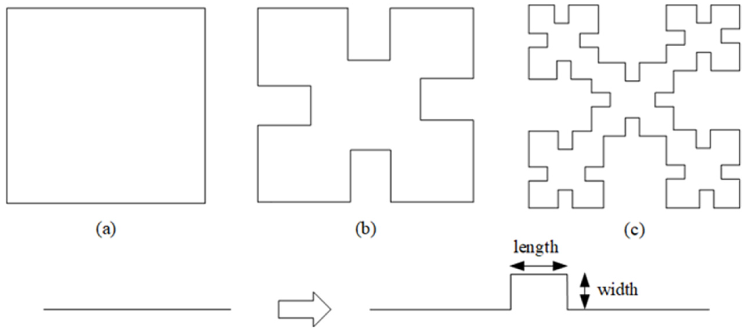
Fractal structures exhibit self-similarity and can be used to miniaturize the antenna structure. In this study, the antenna unit was designed with a first-order Minkowski fractal structure, as shown in the figure, while Figure 2a–c shows 0-order, 1-order, and 2-order structures, respectively.
To clearly describe the unit structure of the proposed antenna, the design process of the antenna unit is shown in Figure 3a–c. Figure 3a–c shows a conventional rectangular microstrip patch antenna (Antenna 1), first-order Minkowski fractal antenna structure unit (Antenna 2), and first-order Minkowski fractal with square slot antenna unit structure (Antenna 3), respectively.
Among them, the antennas in Figure 3a–c consist of three layers, namely, the radiation, dielectric, and metal ground layers located on the upper, middle, and bottom layers, respectively. For comparison and analysis, the structural dimensions of Antenna 1, Antenna 2, and Antenna 3 are the same, and the dielectric substrates consist of R4350 material, with a dielectric constant, tangent loss, and thicknesses of 3.6, 0.0035, and 0.51 mm, respectively.
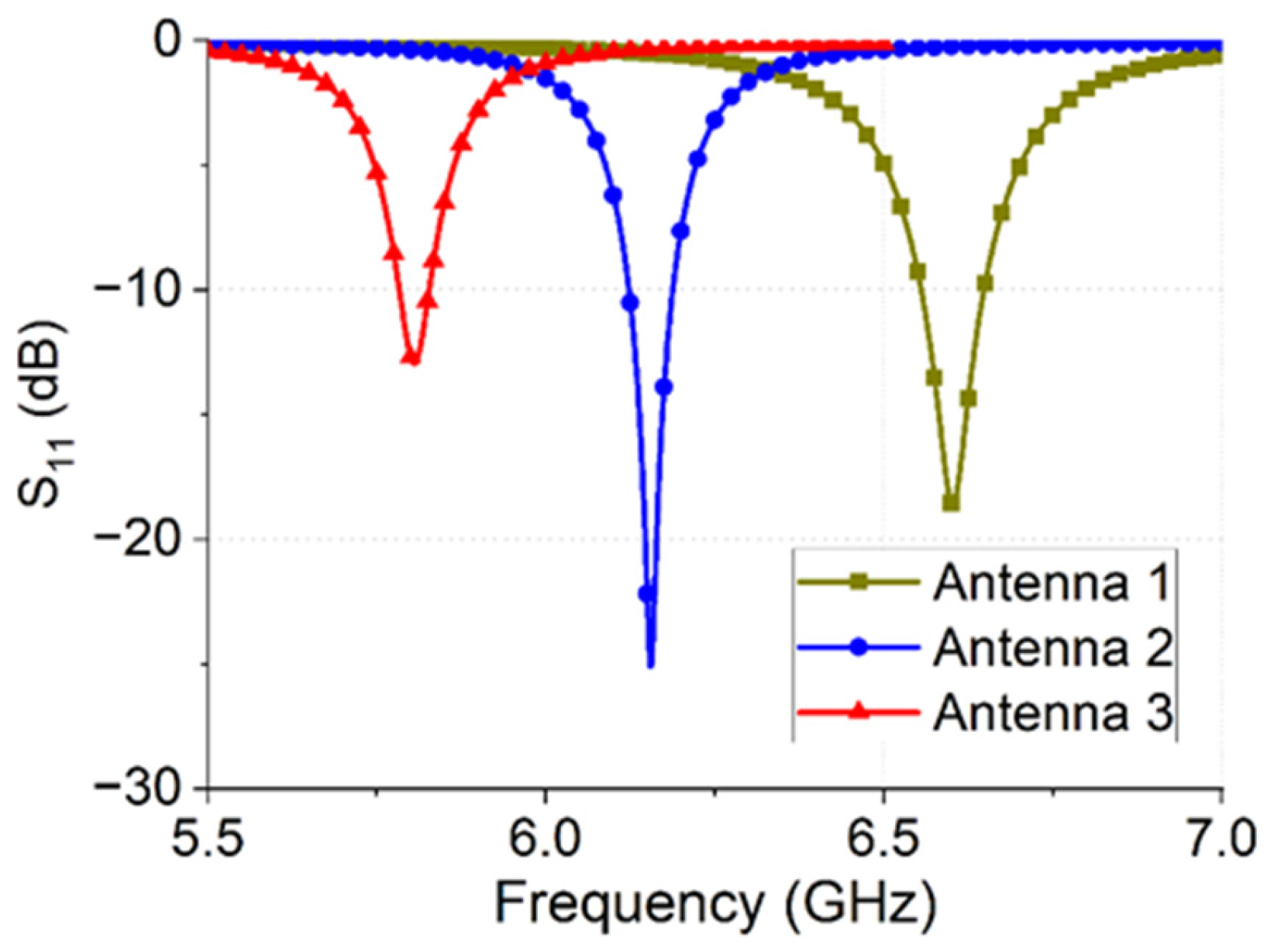
High Frequency Structure Simulator (HFSS) 15.0 was used in this study, and the simulation results of Antennas 1, 2, and 3 are shown in Figure 4. These results indicate that the resonant frequencies of Antennas 1, 2, and 3 are 5.8 GHz, 6.2 GHz, and 6.6 GHz, respectively. A comparison of Antennas 1 and 2 shows that under the same size conditions, Antenna 2 possesses a lower resonant frequency. It is verified that the fractal structure miniaturizes the antenna. A comparison of the antennas in Figure 3b,c shows that the square slot structure reduces the resonant frequency of the antenna, further miniaturizing it.
According to microstrip antenna theory, high gain can be obtained by using an air layer as the dielectric substrate of the antenna unit. Therefore, the antenna unit structure designed in this study used a 2 mm air dielectric layer as the substrate. The structure diagram of the antenna is shown in Figure 5, where Figure 5a shows the antenna dielectric substrate thickness as a microstrip antenna and Figure 5b shows the antenna unit structure with an air dielectric layer.
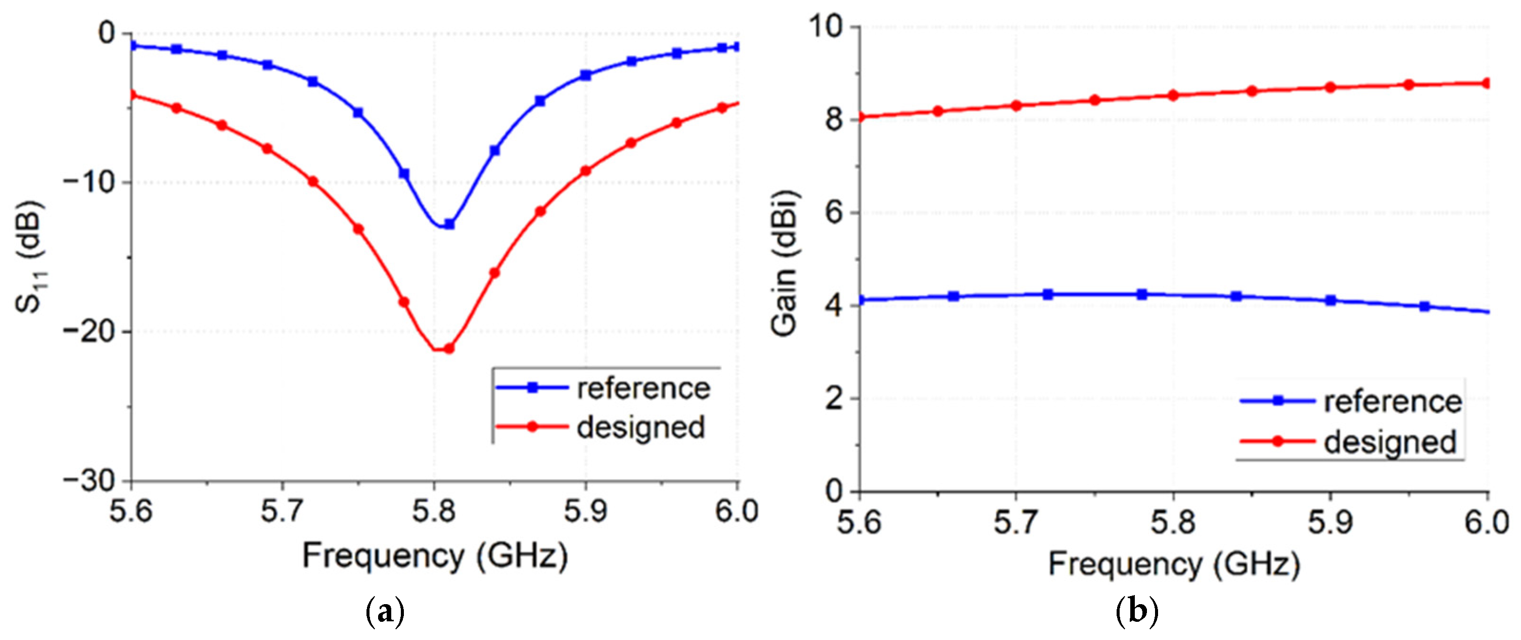
The simulation results of the reference and proposed antennas are shown in Figure 6. Figure 6a indicates that the proposed antenna has a wide working bandwidth compared to the reference antenna because it uses an air dielectric layer with a thickness of 2 mm. Figure 6b shows that, compared with the reference antenna, the proposed antenna has a higher gain. At the operating frequency of 5.8 GHz, the gain of the proposed antenna is 8.9 dBi, which is approximately 5 dB higher than that of the reference antenna.

2.2. 1–4 Power Divider

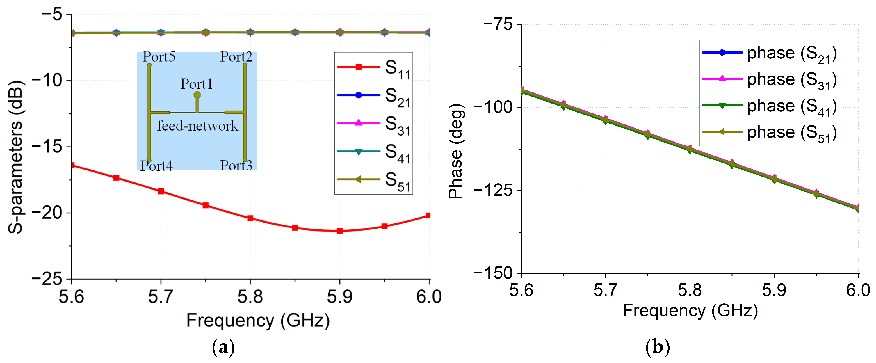
The structure of the 1–4 power divider designed in this work is shown in the figure. The electromagnetic simulation software HFSS was used and optimized. The simulation results are presented in Figure 7a, which shows that within the working frequency band 5.6–6.0 GHz, the insertion loss of the power divider is 0.2 dB. Further, Figure 7b shows that each output port has in-phase.

2.3. Design of Metasurface Units Based on Fractal Structure

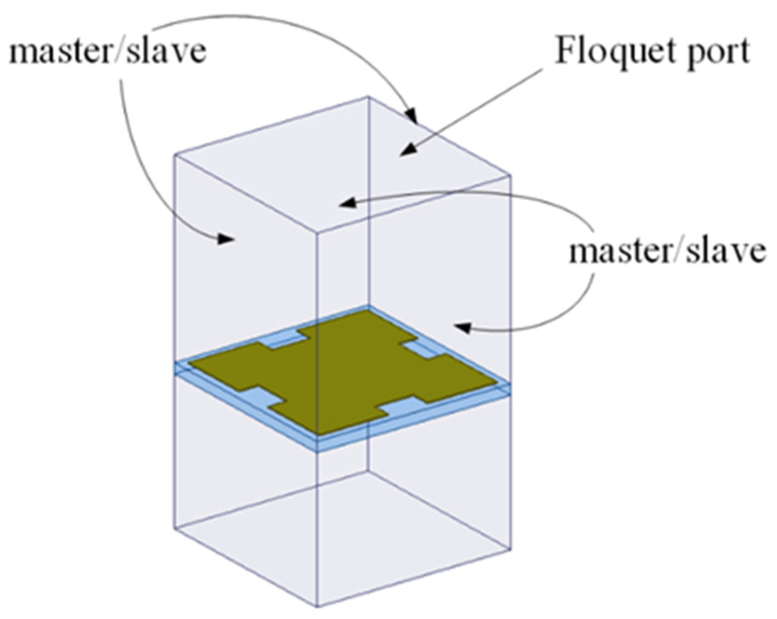
The simulation setting method of the metasurface structural unit is shown in the figure. The master–slave boundary condition is used around the Floquet excitation port, and the simulation results of the metasurface structural unit are shown in Figure 8.
The transmission and reflection coefficients of the metasurface unit can be obtained from Figure 9a. The phase of the metasurface unit is shown in Figure 9b. At the working frequency, the height is approximately a half wavelength, and 180° of the reflective phase is obtained.

3. Results and Discussion

3.1. Parameter Analysis of the Array Antenna

The main parameters of the antenna, such as the height of the air dielectric layer, were analyzed to study the impact of the various parameters of the antenna on its performance.
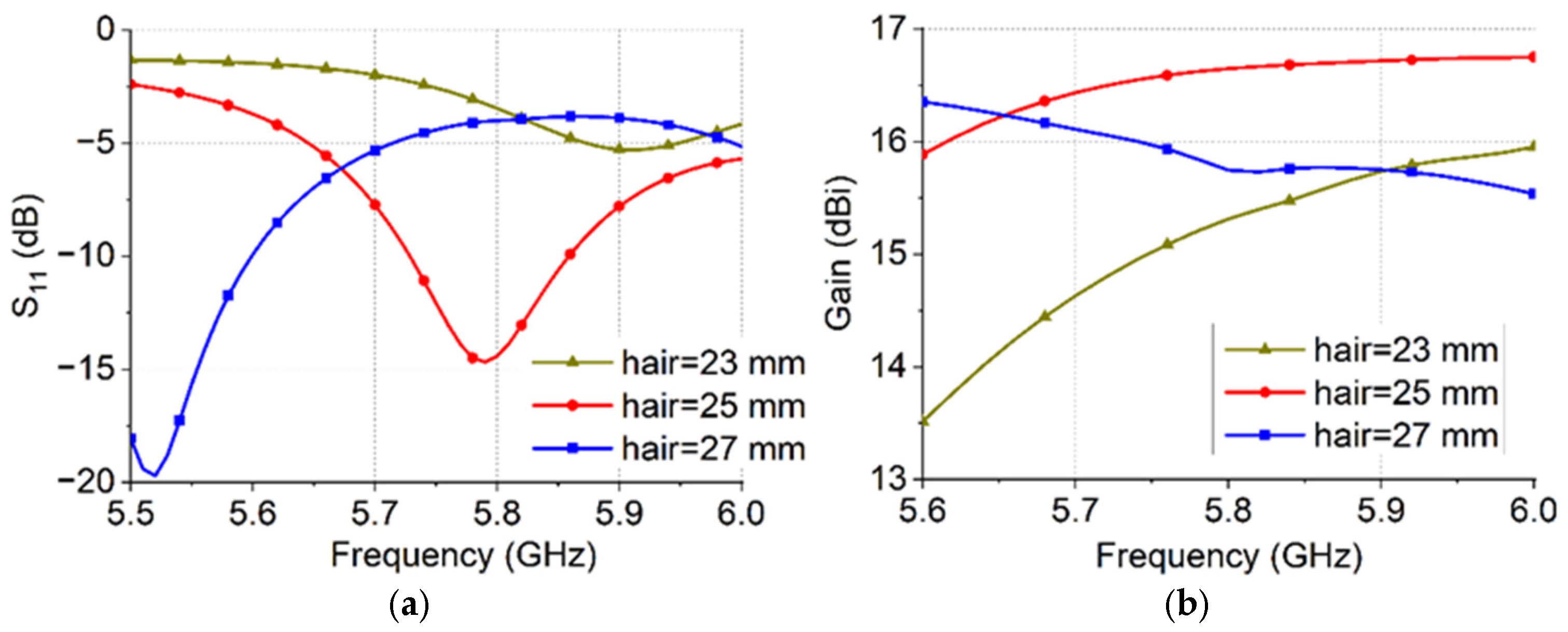
(1) Figure 10 show the S11 and gain of the antenna when the thickness of the air dielectric layer is changed. When the height changes from 23 mm to 27 mm, the resonant frequency of the antenna decreases from 5.9 GHz to 5.52 GHz. In addition, the change in height affects the matching of the antenna. Figure 10b shows that at 5.8 GHz, the gain of the antenna increases from 15.5 dBi to 16.6 dBi and again decreases to 15.8 dBi as the height increases.
The above analysis shows that the thickness of the air dielectric layer considerably affects the S11 and gain of the antenna. Based on electromagnetic theory, when the height is half-wavelength, the phase difference between the electromagnetic waves radiated by the antenna and the reflected electromagnetic waves is 180°. Thus, the electric field satisfies the superposition relationship, which effectively improves the gain of the antenna. When the height does not meet the half-wavelength relationship, the phases of the two do not satisfy the inverse phase relationship, which affects the gain of the antenna.
(2) The number of units of the metasurface array structure, S11, and the gain of the antenna are shown in Figure 11. Figure 11a,b shows that as the number of units increases, when the resonance frequency of the antenna changes from 4 × 4 to 8 × 8, the resonance frequency of the antenna varies from 5.78 GHz to 5.9 GHz; in addition, the gain of the array antenna varies from 14.5 dBi to 16.6 dBi. These results indicate that more metasurface array structural units correspond to larger structural size and greater gain of the antenna.
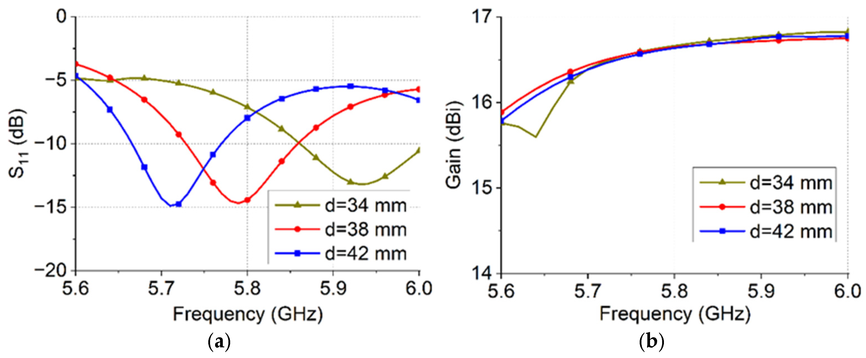
(3) The spacing between array antenna units, the S11, and the gain of array antennas are shown in Figure 12. The figures show that as the spacing of the antenna units varies from 34 mm to 42 mm, the resonance frequency of the antenna varies from 5.95 GHz to 5.7 GHz. According to the theoretical analysis of the array antenna, the gain of the 2 × 2 array antenna may be increased to a certain extent by increasing the distance between the antenna units. Considering the FP antenna designed in this study, the metasurface array structure needs to be comprehensively considered during design. The simulation results indicate that at the operating frequency of 5.8 GHz, when the antenna units have different spacing, the effect on the gain of the array antenna is small and it fluctuates slightly.

3.2. Antenna Without/with Metamaterial Superstrate

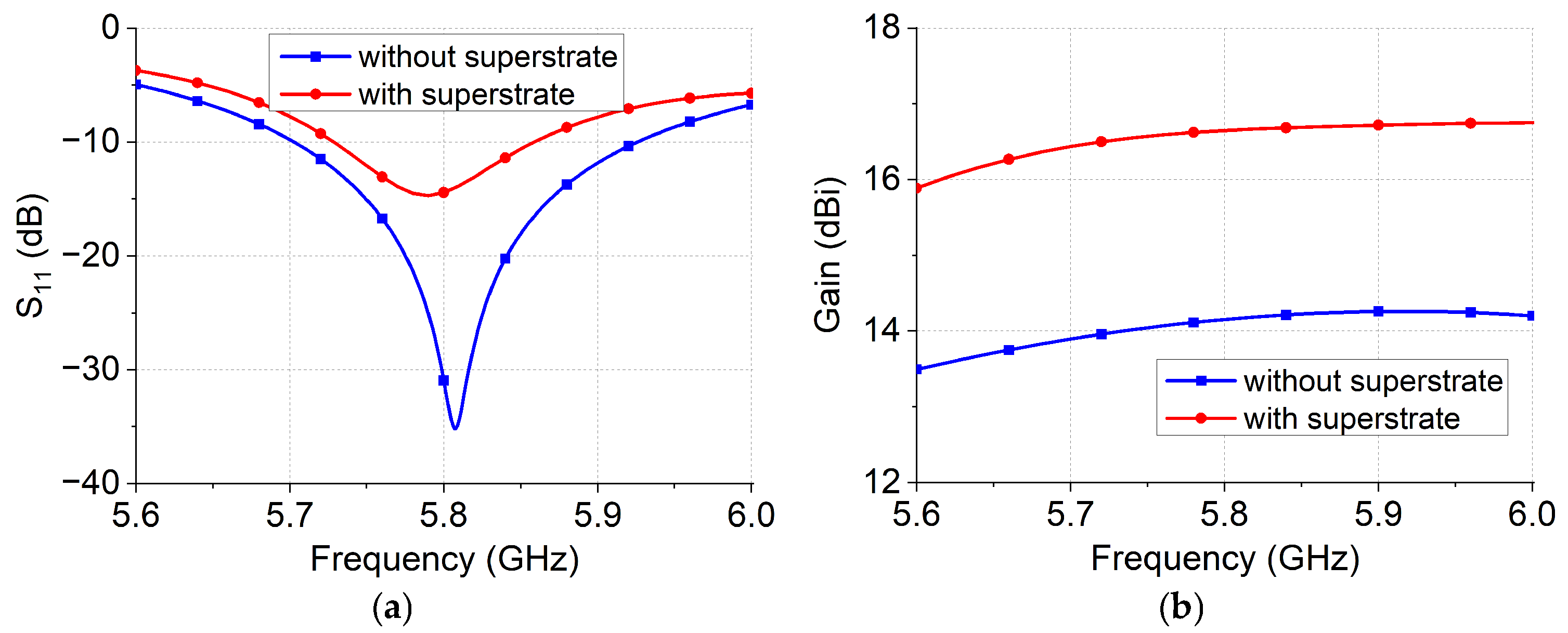
To further verify and analyze the effect of the metamaterial superstrate on array antenna gain, Figure 13a shows the fractal 2 × 2 array antenna structure (without superstrate layer); Figure 13b shows the array antenna with metamaterial superstrate layer designed in this paper.
Figure 13 shows the simulation results of the −10 dB working bandwidth and gain of the two array antennas. Considering the metamaterial structural units, the metamaterial superstrate loading array antenna of −10 dB working bandwidth is about 5.72–5.86 GHz, while the reference antenna array without metamaterial superstrate layer is 5.7–5.92 GHz. Through comparative analysis, the metamaterial superstrate layer affects the antenna’s working bandwidth.
From Figure 13b, it can be analyzed that the antenna gain of the array antenna designed in this paper is higher by about 2.2 dB compared to the reference antenna without metamaterial superstrate layer, and the metamaterial superstrate layer has a significant effect on the antenna gain.

3.3. Processing and Testing of Array Antennas

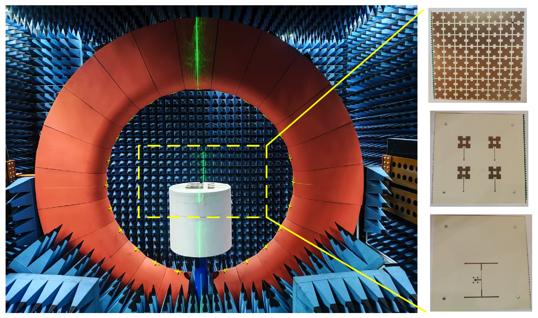
Figure 14 shows the processing of the array antenna for experimentally verifying its accuracy. A network analyzer was used to measure the S11 of the array antenna, and its radiation characteristics were measured in an anechoic chamber. The measured platform is shown in the figure.
The simulation results of the array antenna are shown in Figure 15, which shows that its −10 dB working bandwidth is 5.71–5.89 GHz. Within the frequency band, the gain of the array antenna is higher than 16.2 dBi, whereas at the operating frequency of 5.8 GHz, the gain of the array antenna is 16.5 dBi. Radiation efficiency is more than 90% over the working bandwidth.
The normalization pattern of the E- and H-planes of the antenna is shown in Figure 16. Figure 16a,b, shows that in the E-plane of the antenna, the cross-polarization ratio exceeds 25 dB, whereas the cross-polarization ratio on the H-plane is lower than 28 dB; the antenna has lower cross-polarization characteristics.
A comparison of the performance of the array antennas designed in this study with those previously reported indicated that at 5.8 GHz, the designed FP antenna possessed higher gain (see Table 1). In addition, it had a lower profile height, which was advantageous. This antenna is suitable for longer distance wireless system.

4. Conclusions

In this study, a high-gain linear polarized FP antenna was designed based on fractal structure. Both the antenna and metasurface units possessed a first-order Minkowski fractal structure, which miniaturized the antenna structure unit. To improve the gain of the antenna, the antenna unit contained an air dielectric layer and 1–4 power divider to realize a 2 × 2 array antenna. The performance of the antenna was verified and analyzed. The experimental results showed that the −10 dB working bandwidth of the antenna was 5.71–5.89 GHz, and the gain of the array antenna at 5.8 GHz reached 16.5 dBi, with a higher gain. The proposed antenna has potential for application in wireless communication systems.

Author Contributions

Conceptualization, T.T., L.P. and T.S.A.; methodology, W.H. and M.A.A.; data curation, T.S.A.; validation, W.H.; writing—original draft preparation, M.A.A.; writing—review and editing, W.H. and T.S.A.; funding acquisition, W.H., T.T. and T.S.A. All authors have read and agreed to the published version of the manuscript.

Funding

This work was supported by the Southwest Minzu University Research Startup Funds (RQD2021060) and the Sichuan Provincial Science and Technology Department Key Project (2025YFHZ0013). Also, this study is supported via funding from Prince Sattam bin Abdulaziz University project (PSAU/2025/R/1447).

Data Availability Statement

The original contributions presented in the study are included in the article; further inquiries can be directed to the corresponding author.

Conflicts of Interest

The authors declare that there is no conflict of interest regarding the publication of this article.

References

  1. Wong, H.; Luk, K.M.; Chan, C.H.; Xue, Q.; So, K.K.; Lai, H.W. Small Antennas in Wireless Communications. Proc. IEEE 2012, 100, 2109–2121. [Google Scholar] [CrossRef]
  2. Mietzner, J.; Schober, R.; Lampe, L.; Gerstacker, W.; Hoeher, P. Multiple-Antenna Techniques for Wireless Communications—A Comprehensive Literature Survey. IEEE Commun. Surv. Tutor. 2009, 11, 87–105. [Google Scholar] [CrossRef]
  3. Chakraborty, U. A Comact Microstrip Patch Antenna for Wireless Communication. Prog. Electromagn. Res. C 2011, 18, 211–220. [Google Scholar] [CrossRef]
  4. Gianvittorio, J.P.; Rahmat-Samii, Y. Fractal Antennas: A Novel Antenna Miniaturization Technique, and Applications. IEEE Antennas Propag. Mag. 2002, 44, 20–36. [Google Scholar] [CrossRef]
  5. Oraizi, H.; Hedayati, S. Miniaturization of Microstrip Antennas by the Novel Application of the Giuseppe Peano Fractal Geometries. IEEE Trans. Antennas Propag. 2012, 60, 3559–3567. [Google Scholar] [CrossRef]
  6. Patel, S.K.; Baz, A. O-Shape Fractal Antenna Optimized Design with Broad Bandwidth and High Gain for 6G Mobile Communication Devices. Fractal Fract. 2024, 8, 17. [Google Scholar] [CrossRef]
  7. Vallappil, A.K.; Khawaja, B.A.; Rahim, M.K.A.; Uzair, M.; Jamil, M.; Awais, Q. Minkowski–Sierpinski Fractal Structure-Inspired 2 × 2 Antenna Array for Use in Next-Generation Wireless Systems. Fractal Fract. 2023, 7, 158. [Google Scholar] [CrossRef]
  8. Yaminisasi, G.; Pardhasaradhi, P.; Prasad, N.; Madhav, B.T.P.; Algarni, A.D.; Das, S.; El Ghzaoui, M. Fish-Tail Structured Fractal Monopole Printed Antenna with Dual Broadband Characteristics for Sub–6 GHz 5G and X–Band Radar Applications. Fractal Fract. 2025, 9, 29. [Google Scholar] [CrossRef]
  9. Joseph, E.; Kumar, P.; Afullo, T. Design and Performance Evaluation of a Second-Order Iterated Circular Minkowski Fractal Antenna for Ultra-Wideband Applications. Fractal Fract. 2023, 7, 806. [Google Scholar] [CrossRef]
  10. Tumakov, D.; Chikrin, D.; Kokunin, P. Miniaturization of a Koch-Type Fractal Antenna for Wi-Fi Applications. Fractal Fract. 2020, 4, 25. [Google Scholar] [CrossRef]
  11. Sabban, A. Novel Meta-Fractal Wearable Sensors and Antennas for Medical, Communication, 5G, and IoT Applications. Fractal Fract. 2024, 8, 100. [Google Scholar] [CrossRef]
  12. Attioui, S.; Khabba, A.; Ibnyaich, S.; Zeroual, A.; Zakaria, Z.; Al-Gburi, A.J.A. Design of a Miniaturized Circular Flower-Shaped Fractal Antenna with a Defected Ground Structure for Multiband Applications. Prog. Electromagn. Res. C 2025, 155, 203–211. [Google Scholar] [CrossRef]
  13. Gheethan, A.A.; Herzig, P.A.; Mumcu, G. Compact 2 × 2 Coupled Double Loop GPS Antenna Array Loaded with Broadside Coupled Split Ring Resonators. IEEE Trans. Antennas Propag. 2013, 61, 3000–3008. [Google Scholar] [CrossRef]
  14. Temga, J.; Motoyoshi, M.; Shiba, T.; Suematsu, N. A5.5GHz-Band 2x2 Array Antennas Module Based on Compact 2-D Beamforming Network in Broadside Coupled Stripline. In Proceedings of the 2022 16th European Conference on Antennas and Propagation (EuCAP), Madrid, Spain, 27 March–1 April 2022; pp. 1–4. [Google Scholar] [CrossRef]
  15. Phakaew, T.; Pongthavornkamol, T.; Torrungrueng, D.; Dallmann, T.; Chalermwisutkul, S. A Wideband 4 × 4 Patch Array Antenna with Low Sidelobes for Radar-Based Obstacle Detection in Railway Transportation. IEEE Open J. Antennas Propag. 2025, 6, 774–788. [Google Scholar] [CrossRef]
  16. Huang, K.Q.; Swaminathan, M. Antenna Array on Glass Interposer for 6G Wireless Communications. IEEE Trans. Compon. Packag. Manuf. Technol. 2023, 13, 211–218. [Google Scholar] [CrossRef]
  17. Alblaihed, K.A.; Abbasi, Q.H.; Imran, M.A.; Mohjazi, L. Gain Enhancement Using Superstrate of Microstrip Patch Antenna Array for 5G Applications. In Proceedings of the 2024 IEEE International Symposium on Antennas and Propagation and INC/USNC-URSI Radio Science Meeting (AP-S/INC-USNC-URSI), Firenze, Italy, 14–19 July 2024; pp. 2705–2706. [Google Scholar] [CrossRef]
  18. Francis, R.; Butt, S.I.; Singh, J.; Hein, M.A. Dielectric Superstrate Structures for Gain Enhancement of a Patch Antenna in the Ku-Band. In Proceedings of the 2025 16th German Microwave Conference (GeMiC), Dresden, Germany, 17–19 March 2025; pp. 1–4. [Google Scholar] [CrossRef]
  19. Ponti, C.; Ceccuzzi, S.; Baccarelli, P.; Schettini, G. A Resonant-Cavity Antenna with High-Gain and Wide Bandwidth with an All-Dielectric 3D-Printed Superstrate. IEEE Access 2024, 12, 111982–111991. [Google Scholar] [CrossRef]
  20. Feng, Y.; Yang, Y.; Zhang, L.K.; Yang, Y.H.; Zhou, S.G.; Li, J.Y.; Yang, G.W. A 2-D Wideband and Wide Beam-Steering Phased Array Antenna with a Combined Superstrate for 5G Sub-6 GHz Applications. IEEE Trans. Circuits Syst. II Express Briefs 2024, 71, 3720–3724. [Google Scholar] [CrossRef]
  21. He, Y.; Lin, W.; Zhao, L. Wide-Angle Beam-Scanning Millimeter-Wave Linear Antenna Arrays Facilitated by a Slim High Dielectric-Constant Superstrate. IEEE Trans. Antennas Propag. 2025, 73, 6241–6251. [Google Scholar] [CrossRef]
  22. Gupta, R.K.; Mukherjee, J. Effect of Superstrate Material on a High-gain Antenna Using Array of Parasitic Patches. Microw. Opt. Technol. Lett. 2010, 52, e24850. [Google Scholar] [CrossRef]
  23. Yang, W.; Chen, S.; Che, W.; Xue, Q.; Meng, Q. Compact High-Gain Metasurface Antenna Arrays Based on Higher-Mode SIW Cavities. IEEE Trans. Antennas Propag. 2018, 66, 4918–4923. [Google Scholar] [CrossRef]
  24. Singh, A.K.; Abegaonkar, M.P.; Koul, S.K. High-Gain and High-Aperture-Efficiency Cavity Resonator Antenna Using Metamaterial Superstrate. IEEE Antennas Wirel. Propag. Lett. 2017, 16, 2388–2391. [Google Scholar] [CrossRef]
  25. Asaadi, M.; Afifi, I.; Sebak, A.R. High Gain and Wideband High Dense Dielectric Patch Antenna Using FSS Superstrate for Millimeter-Wave Applications. IEEE Access 2018, 6, 38243–38250. [Google Scholar] [CrossRef]
  26. Sharma, A.; Ram, S.; Vasistha, P.; Kanaujia, B.K.; Gangwar, D.; Singh, S.P.; Lay-Ekuakille, A. Characterization and Performance Enhancement of 4 × 4 Microstrip Antenna Array in Dusty Atmosphere Using Metasurface Based Superstrate. Meas. J. Int. Meas. Confed. 2024, 235, 114736. [Google Scholar] [CrossRef]
  27. Ding, H.; Liu, N.; Jiang, T.; Sheng, X.; Liu, X. Wideband High Gain and Low RCS Fabry–Perot Antenna Using the Single Layer Partially Reflective Surface. Microw. Opt. Technol. Lett. 2024, 66, e70045. [Google Scholar] [CrossRef]
  28. Le, H.D.; Le-Huu, T.; Nguyen, K.K.; Ta, S.X. Dual Circularly Polarized Fabry-Perot Antenna Using Single-Layer Self-Polarizing PRS. IEEE Antennas Wirel. Propag. Lett. 2023, 22, 2575–2579. [Google Scholar] [CrossRef]
  29. Fu, Y.; Liu, Z.; Zeng, Y.; Xu, H.; Yan, J. A Low-Profile Broadband Gain Enhancement Fabry-Pérot Antenna with an Array Source and Vertical Metal Walls. Microw. Opt. Technol. Lett. 2025, 67, 18–21. [Google Scholar] [CrossRef]
  30. Lv, Y.H.; Ding, X.; Wang, B.Z. Dual-Wideband High-Gain Fabry-Perot Cavity Antenna. IEEE Access 2020, 8, 4754–4760. [Google Scholar] [CrossRef]
  31. Khouser, G.H.; Choukiker, Y.K.; Bhowmick, A. Gain Enhancement in Microstrip Patch Antenna with High Negative Refractive Index 3D-Metamaterial Inspired Superstrate for Wireless Applications. IEEE Access 2024, 12, 7372–7381. [Google Scholar] [CrossRef]
  32. Gil-Martinez, A.; Poveda-Garcia, M.; Canete-Rebenaque, D.; Gomez-Tornero, J.L. Metasurface Antenna for Fast Frequency Scanning with Application to Conical Direction Finding. IEEE Antennas Wirel. Propag. Lett. 2023, 22, 1632–1636. [Google Scholar] [CrossRef]
  33. Fang, S.; Zhang, L.; Guan, Y.; Weng, Z.; Wen, X. A Wideband Fabry-Perot Cavity Antenna with Single-Layer Partially Reflective Surface. IEEE Antennas Wirel. Propag. Lett. 2023, 22, 412–416. [Google Scholar] [CrossRef]
  34. Sengupta, R.; Chatterjee, A.; Banerjee, S.; Parui, S.K.; Mitra, M. Gain Enhancement of Substrate Integrated Waveguide Based Cavity-Backed Slotted Planar Antenna Array Using FSS Superstrate. In Proceedings of the 2024 IEEE Microwaves, Antennas, and Propagation Conference (MAPCON), Hyderabad, India, 9–13 December 2024; pp. 1–5. [Google Scholar] [CrossRef]
  35. Boukern, D.; Bouacha, A.; Aissaoui, D.; Belazzoug, M.; Denidni, T.A. High-Gain Cavity Antenna Combining AMC-Reflector and FSS Superstrate Technique. Int. J. RF Microw. Comput. Eng. 2021, 31, e22674. [Google Scholar] [CrossRef]
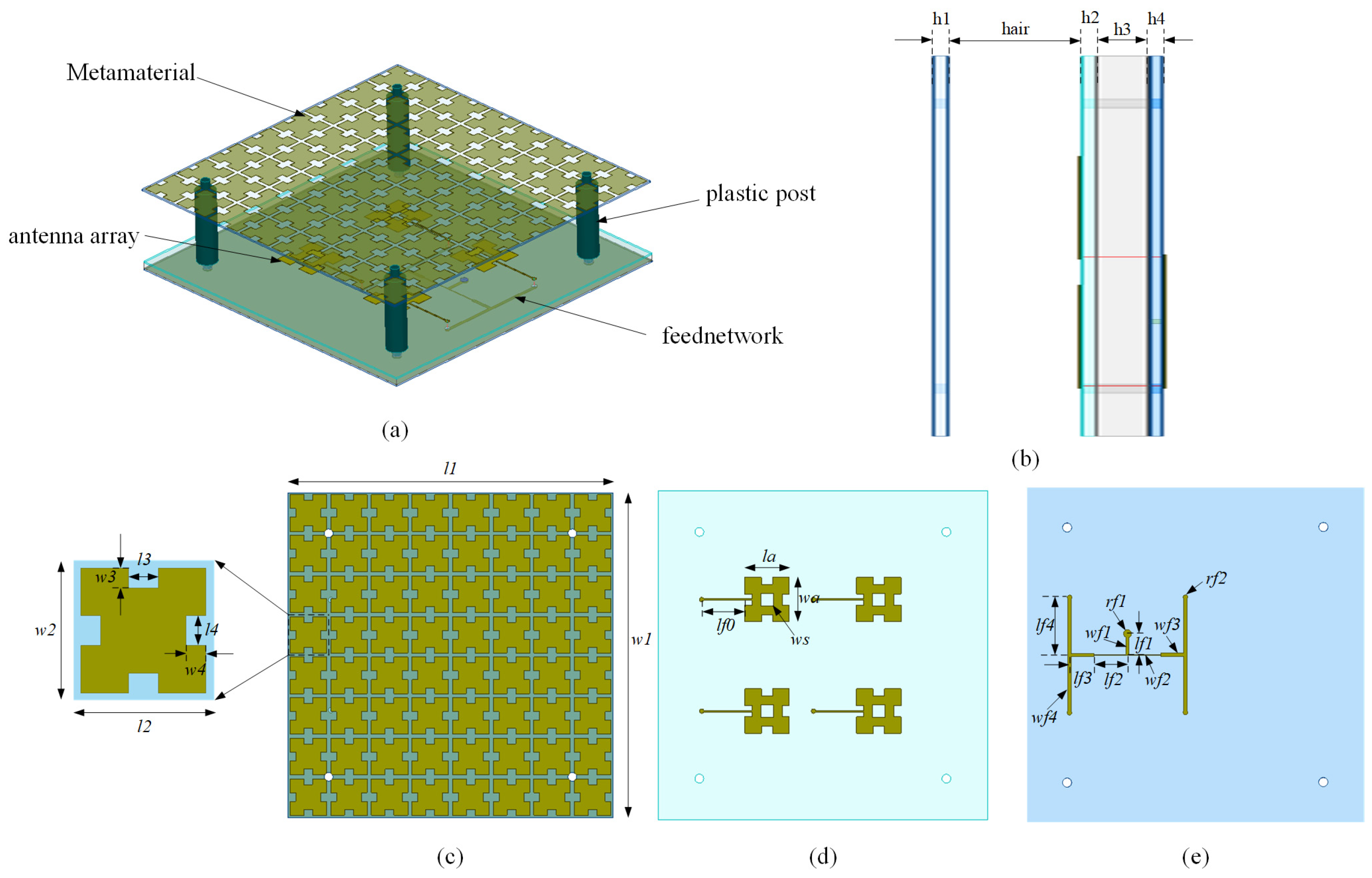
Figure 1. Antenna structure. (a) 3D, (b) side view of antenna, (c) front view of FSS superstrate, (d) front view of 2 × 2 antenna array, and (e) front view of feed network.
Fractalfract 09 00685 g001
Figure 2. The 0–2nd order Minkowski fractal structure. (a) Order 0, (b) Order 1, (c) Order 2.
Fractalfract 09 00685 g002
Figure 3. Antenna unit design process. (a) Conventional microstrip antenna, (b) first-order Minkowski fractal structure antenna unit, (c) first-order Minkowski fractal structure with square slot antenna unit.
Fractalfract 09 00685 g003
Figure 4. S11 simulation result of the antenna unit structure.
Fractalfract 09 00685 g004
Figure 5. Structure of the antenna unit. (a) Front view of the comparison antenna, (b) side view of the comparison antenna, (c) front view of the proposed antenna, (d) side view of the proposed antenna.
Fractalfract 09 00685 g005
Figure 6. Comparison of the performances of the proposed and reference antenna. (a) S11, (b) gain.
Fractalfract 09 00685 g006
Figure 7. Simulation results for the power divider. (a) Amplitude between each port, (b) phase with each output port.
Fractalfract 09 00685 g007
Figure 8. Simulation of the metasurface structural unit.
Fractalfract 09 00685 g008
Figure 9. Simulation results of the ports. (a) S parameter, (b) phase.
Fractalfract 09 00685 g009
Figure 10. Simulation results of the antenna for changes in the height of the air dielectric layer. (a) S11, (b) gain.
Fractalfract 09 00685 g010
Figure 11. Simulation results of the antennas corresponding to changes in the number of structural units of the metasurface arrays. (a) S11, (b) gain.
Fractalfract 09 00685 g011
Figure 12. Simulation results of antennas at different spacings of antenna units. (a) S11, (b) gain.
Fractalfract 09 00685 g012
Figure 13. Simulation results of antennas with/without superstrate. (a) S11, (b) gain.
Fractalfract 09 00685 g013
Figure 14. Measured platform of array antenna.
Fractalfract 09 00685 g014
Figure 15. S11 and gain of the array antenna. (a) S11, (b) gain and radiation efficiency.
Fractalfract 09 00685 g015
Figure 16. Radiation pattern of the array antenna. (a) E-plane, (b) H-plane.
Fractalfract 09 00685 g016
Table 1. The performance of designed antenna compared with the antenna in the literature.
ReferencesCenter FrequencyAntenna StructureSize (λ03)Bandwidth (GHz)Gain (dBi)
[19]5.8Single layer PRS0.96 × 0.96 × 0.0695.69–6.010.75
[23]5.8Single layer PRS1.56 × 1.56 × 0.495.7–6.6512.7
[26]5.8Single layer PRS1.54 × 1.93 × 0.925.57–5.7 and 5.79–5.8316
[27]10.5Single layer PRS2.45 × 2.45 × 0.728.6–11.816.3
[28]5.8Single layer PRS2.51 × 2.51 × 0.615.5–6.1613.7
[29]10Single layer PRS3.0 × 3.0 × 0.249.59–10.5715.56
[32]5.2Single layer PRS and HIS8.67 × 8.67 × 0.335.1–5.314.0
[33]9.5Single layer PRS2.1 × 2.1 × 0.578.0–11.013.7
Paper5.8Single layer PRS2.16 × 2.16 × 0.575.71–5.89 16.5
Disclaimer/Publisher’s Note: The statements, opinions and data contained in all publications are solely those of the individual author(s) and contributor(s) and not of MDPI and/or the editor(s). MDPI and/or the editor(s) disclaim responsibility for any injury to people or property resulting from any ideas, methods, instructions or products referred to in the content.