Article

Hardware-in-the-Loop Experimental Validation of a Fault-Tolerant Control System for Quadcopter UAV Motor Faults

1
Department of Electrical Engineering, National University of Computer and Emerging Sciences—FAST, Islamabad 44000, Pakistan
2
School of Engineering and Physical Sciences, Heriot-Watt University, Edinburgh EH14 4AS, UK
3
Government College of Technology Nowshera, Khyber Pakhtunkhwa Technical Education & Vocational Training Authority, Peshawar 25000, Pakistan
4
Department of Electrical Engineering, College of Engineering, King Faisal University, Alahsa 31982, Saudi Arabia
5
Smart Grids Research Group, Center of Research Excellence in Renewable Energy and Power Systems, King Abdulaziz University, Jeddah 21589, Saudi Arabia
6
Department of Electrical and Computer Engineering, Faculty of Engineering, King Abdulaziz University, Jeddah 21589, Saudi Arabia
*
Authors to whom correspondence should be addressed.
Fractal Fract. 2025, 9(11), 682; https://doi.org/10.3390/fractalfract9110682
Submission received: 30 August 2025 / Revised: 10 October 2025 / Accepted: 14 October 2025 / Published: 23 October 2025

Abstract

In this paper, a hybrid fault-tolerant control (FTC) system for quadcopter unmanned aerial vehicles (UAVs) is proposed to counteract the deterioration of the performance of the quadcopter due to motor faults. A robust and adaptive approach to controlling fault conditions is simulated by combining an integral back-stepping controller for translational motion and a nonlinear observer-based sliding-mode controller for rotational motion, and then implemented on an FPGA. Finally, motor faults are treated as disturbances and are successfully compensated by the controller to ensure safe and high-performance flight. Simulations were taken at 0%, 10%, 30%, and 50% motor faults to test how effective the proposed FTC system is. After simulations, the controller’s real-time performance and reliability were validated through hardware-in-the-loop (HIL) experiments. The results validated that the proposed hybrid controller can guarantee stable flight and precision tracking of the desired trajectory when any single motor fails up to the order of 50%. It shows that the controller is of high fault tolerance and robustness, which will be a potential solution for improving the reliability of UAVs in fault-prone conditions.

1. Introduction

Unmanned aerial vehicles (UAVs) have received a lot of attention for development since the early 2000s due to their usage in different applications like defense operations [1], entertainment [2], agriculture [3], etc. Quadcopter UAVs are also increasing due to improvements in electrical technology, long-duration batteries, low-cost inertial measurement devices, fast microprocessors, and commercial and lab-built prototypes [4,5]. However, because quadcopters have four input forces—the push from each propeller attached to each rotor at a constant pitch angle—and complicated, nonlinear dynamics, the field of control systems experts has become more interested in this subject [6]. Quadcopters are currently popular among UAVs, consisting of four propellers spinning with brushless DC motors. These propellers rotate to create the required lift to allow the quadcopter to be airborne [7]. Furthermore, the differential speeds of individual rotors are utilized to tame the quadcopter’s orientation by producing torque and to provide attitude control. However, the presence of a fault in any motor of the quadcopter can lead to the cancellation of the operation [8]. For attitude stabilization, trajectory-tracking control strategies including PID controllers [9], backstepping methods [10], disturbance rejection approaches [11], and adaptive control [12] ideas have been proposed. Nevertheless, the vast majority of these methods assume fault-free operation, neglecting to account for motor failure or faults caused by wear and tear or damage to the motor and propeller components. These faults can severely pose safety risks degrading altitude and attitude control.
Since there are various sources of faults, fault-tolerant control (FTC) strategies have become attractive to improve the reliability and safety of quadcopter UAVs. FTC systems are typically categorized into two approaches: active FTC and passive FTC [13]. Early detection and isolation can avoid severe system failures which, in turn, can support condition-based maintenance. However, the hardware implementation of the FTC system is a challenging task, due to which many proposed FTC systems are limited to simulations only. In this work, we have contributed in three ways: (a) we designed a hybrid control for the translational and rotational motion control of the quadcopter; (b) we implemented the proposed hybrid control system on the FPGA model; and (c) instead of relying on a single evaluation metric, several evaluation metrics are considered during the experimental analyses.
The design, analysis, and implementation of the fault-tolerant control system based on integral backstepping (IBS) and nonlinear observer-based sliding mode (NL-DO-SM) control to achieve altitude- and attitude-tracking capability in quadcopter UAVs is presented in this paper. The proposed hybrid controller addresses modeling uncertainties, potential actuator failures, and nonlinear quadcopter dynamics. It adapts to situations with uncertain fault magnitudes, represented as partial loss of effectiveness (LOE) in rotor thrust. The controller ensures asymptotic convergence of altitude and attitude-tracking errors, maintaining system resilience against uncertainties. Real-time hardware-in-the-loop (HIL) studies have validated the hybrid controller. Experimental results demonstrate the effectiveness and robustness of the proposed fault-tolerant control (FTC) method.
The structure of this paper is organized as follows: In Section 2, literature review is covered, and Section 3 presents the mathematical modeling for the quadcopter. The design and analysis of the proposed FTC is presented in Section 4. The implementation and experimental validation results of the real-time implementation is given in Section 5, and finally, in Section 6, a conclusion is given.

2. Literature Review

Recently, research on micro aerial vehicles (MAVs), particularly quadcopter MAVs, has been quite extensive due to their wide range of applications. This inherent agility, technological ease of use, and low cost have led researchers to utilize the quadcopter model to explore advanced control strategies and enhance flight performance. This section presents major studies and important progress made in designing, controlling, and fault-tolerant operation of quadcopter MAVs. To address the ongoing challenges in providing reliable and robust performance of quadcopters operating under different operational conditions, various control methodologies, fault detection mechanisms, and control techniques proposed by researchers have been proposed.
In [14], the author designed and experimentally validated fault-tolerant control (FTC) laws for a multi-copter UAV based on gain scheduling (GS) control and structured H synthesis. Successful flight experiments with a hexacopter were performed to validate the proposed recovery strategies; successful hovering and trajectory tracking under actuator faults were demonstrated with 40% fault tolerance. In this experiment, an artificially induced loss of actuator effectiveness (LAE) through motor speed command adjustments is considered. The proposed model handled less fault which must be increased by utilizing more advanced control techniques.
In [15], a nonlinear robust adaptive FTC system for quadcopter altitude and attitude tracking was analyzed. The proposed control system was based on backstepping techniques and guaranteed asymptotic convergence of tracking errors in the presence of a single actuator fault and modeling uncertainties. The main results showed that the quadcopter followed the circular trajectory with sinusoidal orientation using real-time data to evaluate the performance of the FTC algorithm. However, this experiment was carried out in a controlled environment, and only tracked-trajectory analysis was considered.
A proportional–integral–derivative-type FTC (PIDFTC) system for fixed-wing UAVs was analyzed in this paper. The results included integrating prescribed performance functions with a PID-type filter to form an attitude-tracking error, and a composite learning algorithm combining a neural network and disturbance observer to combat induced faults. The Lyapunov analysis verified the uniform ultimate boundedness of the tracking errors. The proposed control scheme was demonstrated through hardware-in-the-loop (HIL) experiments rather than depending on simulations only. This work considers only the tracking angle as a performance measurement for analysis [16].
In [17], an adaptive PID sliding-mode control (PID-SMC) system for the control of quadcopter UAVs with solid external disturbance was addressed. The main result showed that the proposed control method brings about specific fast and finite-time convergence and essentially reduces the chattering effect of control inputs. In this work, the authors verified the analysis through simulations only, with no mention of hardware experiments.
In [18], authors proposed a discrete-time, finite-horizon inear quadratic regulator (LQR) control system for quadcopter UAVs. The main results were through simulation-based analysis only where a feed-forward controller and integrator to account for drag and unmodeled dynamics was proposed and demonstrated that the proposed controller was robust in the presence of large initial heading errors, parametric uncertainty, and state estimation errors. The analysis was purely simulation-based based with no mention of hardware experiments.
In [19], a Time-varying Constrained Model Predictive Controller (TCMPC) was presented for the translational and attitude control of a quadcopter UAV. The results showed that the TCMPC improved the handling of external disturbances, like wind gusts. In addition to simulated examples, real-time hardware experiments were conducted using an ARM A53 processor on a new attitude test setup. This work is limited to only translational motion only; the rotational motion of the quadcopter is not considered during the analysis.
In [20], an improved back-stepping control for nonlinear small UAV systems is simulated for uncertainties handling analysis. The results indicated that an improved back-stepping control does enhance transient performance relative to conventional back-stepping control (BSC), in terms of reducing overshoot and defining a more rapid convergence rate. The method is shown to work and be robust to external disturbances, based on numerical simulations rather than hardware experiments.
An Active Disturbance Rejection Control (ADRC) in conjunction with a Two-Stage Kalman Filter (TSKF) is proposed to handle the fault-tolerant control problems of a quadcopter affected by losses of the effectiveness of its actuators. The results showed that the proposed method greatly improved stability and disturbance rejection performance. The authors performed this analysis through simulations only, which is not enough to check the effectiveness of the control system in more complex environments [21].
This paper presented a robust FTC system for underactuated UAVs using a hierarchical control structure. The authors developed a desired force command in the position loop and a desired torque command in the attitude loop. Simulations validated the control algorithm’s performance and the main results included the control of actuator faults and disturbances using trajectory- and yaw-tracking objectives. Simulations were the basis of the study, but hardware experiments were not. In future work, the limitations of constant actuator faults could have been addressed and the control system’s robustness validated in real-world implementations [22].
In [23], the usage of Fault Estimation (FE) systems with three observers for UAVs—a nonlinear Adaptive Observer (NL-AO), a linear Proportional–Integral Observer (PIO), and a quasi-linear Parameter-Varying PIO—was covered. To absorb soft actuator errors, the results demonstrated the design and experimental validation of a comprehensive active fault-tolerant control architecture. Using the Parrot AR Drone 2.0 as a prototype, the suggested approach was evaluated in real-time during hardware experiments, demonstrating its efficacy in a range of situations.
Additionally, for some classes of nonlinear and memory-dependent dynamics, neural network-based controllers and fractional PID variations enhanced transient shaping and resilience while providing extra tuning degrees of freedom. However, these approaches often involve more modeling and tuning complexity and frequently need more computing effort for real-time implementation, which complicates the deployment on resource-limited embedded devices. Also, the fault-tolerance capabilities are not diminished. Real-time FTC greatly benefits from FPGA-based solutions with low latency, deterministic timings, and parallel computing capabilities. Our proposed control model, in contrast to earlier FTC methods, achieves a balance between analytical tractability and practical robustness: the sliding-mode observer offers fast fault tolerance, the integral action eliminates steady-state bias, and the Lyapunov-based backstepping derivation permits systematic gain selection and stability. In comparison to simulation-centric FTC systems, our FPGA implementation shows the proposed method’s low latency and real-time viability while consuming fewer resources. To provide a workable substitute for both computationally demanding techniques and hardware-focused solutions that lack thorough control theoretic guarantees, our approach combines mathematically demonstrable stability, computational efficiency for embedded deployment, and real-time fault-tolerance capabilities.
Based on the available literature, we can conclude that previous control system models are limited to simulations only. Either translational or rotational motion is selected during analysis, and only trajectory-tracking analysis in a single system is considered, which is not an optimal approach to draw conclusions from the findings. However, in this work, we proposed a new fault-tolerant control system that implements integral back-stepping for translational motion control and nonlinear observer-based sliding-mode control for rotational motion control. We implemented the proposed model on FPGA hardware-based testing for evaluation because most previous research relied only on simulations for validation. The approach advances fault-handling capabilities through broad actuator-fault coverage for motors within the quadcopter, leading to system reliability improvements. This research includes thorough performance evaluations using multiple metrics, which are trajectory analysis in the coordinate system, 3D plane, and roll, pitch, and yaw angles and velocities. The outcomes demonstrate that the fault-tolerant control strategy has the property of robustness and efficiency, thus reducing the difference between theoretical development and practical implementation. Additionally, HIL experiments utilizing the FPGA hardware are used to verify and confirm the system’s ability to operate and reliability.

3. Mathematical Modeling of the Quadcopter

A simplified representation of the quadcopter is illustrated in Figure 1, where the body frame, inertial frame, and the angular velocities associated with the origin are oriented according to the right-hand rule [24]. Motor 1 and motor 3 rotate in a counterclockwise direction, and motor 2 and motor 4 rotate in a clockwise direction. A distance d from the quadcopter’s center of mass, each rotor is associated with a thrust force F s ( s = 1 , , 4 ) directed along the direction of the negative z-axis of the body frame. Further, a reaction torque, τ s , is induced by the rotation of each propeller to the quadcopter structure. A comparison of frames demonstrates the inertial frame to the body frame through which the roll parameter ϕ , pitch parameter θ , and yaw parameter ψ are used. The system features dual rotors that operate in opposite directions. Determining altitude mostly depends on changing the speed outputs from all rotor systems. The control system requires forward movement to increase motor speeds (1,2) alongside reduced speeds for rotor components (3,4) and the opposite sequence for backward movement and vice versa [25,26].
By multiplying the three rotational matrices, the transformation matrix C T is obtained, which gives the angular locations between the body frame’s and the earth frame’s origins as shown by Equation (1).
C T = C ψ · C θ · C φ C T =   cos θ cos ψ sin θ cos ψ sin φ sin ψ cos φ sin ψ sin φ + cos ψ sin θ cos φ sin ψ cos θ sin ψ sin θ sin φ + cos ψ cos φ sin ψ sin θ cos φ cos ψ sin φ sin θ cos θ sin φ cos θ cos φ
Using Lagrangian equations of motion, the Lagrangian function (L) is computed as the difference between the total kinetic energy ( K . E ) and total potential energy ( P . E ) of the system.
L = K . E . P . E .
The Lagrangian for rotational angles is obtained as follows:
d d t L ψ ˙ L ψ = T ψ d d t L ϕ ˙ L ϕ = T ϕ d d t L θ ˙ L θ = T θ
By evaluating the Langrage equations, we get the following rotational equations of motion;
θ ¨ = I r ϕ ˙ Ω I y y + I z x I y y ϕ ˙ ψ ˙ + b l ( Ω 3 2 Ω 1 2 ) I y y K θ θ ˙ 2 ϕ ¨ = I r θ ˙ Ω I x x + I y z I x x ψ ˙ θ ˙ + b l ( Ω 2 2 Ω 4 2 ) I x x K ϕ ϕ ˙ 2 ψ ¨ = I x y I z z ϕ ˙ θ ˙ + d ( Ω 1 2 Ω 2 2 + Ω 3 2 Ω 4 2 ) I z z K ψ ψ ˙ 2
In the above equation, the rotational drag coefficients are represented by K ϕ , K θ , and K ψ , while I x y , I y z , I z x and Ω ¯ are equal to I x x I y y , I y y I z z , I z z I x x and Ω 1 Ω 2 + Ω 3 Ω 4 , respectively.
The mathematical representation for the three translational equations of motion, which are specified as follows, is derived using the Newton–Euler method:
F n e t = O x y z F m g + F drag
The sum of all outside forces acting on the moving quadcopter is F n e t , whereas the gravitational, drag, and thrust forces are O x y z , F m g , and F drag , respectively. The quadcopter’s rotational and translational dynamics in three dimensions are expressed in the state-space by Equation (6), which is used to estimate its motion and create a desirable control system.
x ˙ 1 = x 2 y ˙ 1 = y 2 z ˙ 1 = z 2 φ ˙ 1 = φ 2 θ ˙ 1 = θ 2 ψ ˙ 1 = ψ 2 x ˙ 2 = K x x 2 2 + 1 m u x u 1 y ˙ 2 = K y y 2 2 + 1 m u y u 2 z ˙ 2 = K z z 2 2 g + 1 m ( cos θ 1 cos φ 1 ) u 1 φ ˙ 2 = I r I x x θ 2 Ω ¯ + I y z I x x ψ 2 θ 2 K φ φ 2 2 + l I x x u 2 θ ˙ 2 = I r I y y φ 2 Ω ¯ + I z x I y y ψ 2 φ 2 K θ θ 2 2 + l I y y u 3 ψ ˙ 2 = I x y I z z θ 2 φ 2 K ψ ψ 2 2 + 1 I z z u 4
In above, the u x = sin ψ 1 sin φ 1 + cos ψ 1 sin θ 1 cos φ 1 , u y = sin ψ 1 sin θ 1 cos φ 1 cos ψ 1 sin φ 1 , where u 1 , u 2 , u 3 , and u 4 stand for a quadcopter’s four control inputs, which are pitch, yaw, roll, and thrust control, respectively, and the state vector X is represented as:
X = x 1 y 1 z 1 x 2 y 2 z 2 φ 1 θ 1 ψ 1 φ 2 θ 2 ψ 2 = x y z x ˙ y ˙ z ˙ φ θ ψ φ ˙ θ ˙ ψ ˙
The thrust force and torque generated by the i-th motor are expressed as:
T i = C t ρ Ω i 2 D 4 = b Ω i 2
Q i = C d ρ Ω i 2 D 5 = k T i = d Ω i 2
where k = 2.07 × 10 2 m .
The control input vector u is defined as:
u =   T M x M y M z
The total thrust T combines all four motors’ thrust force to enable vertical flight actions covering hovering and the ascent or descent phases equal to i = 1 4 T i . The rolling torque ( M x ) serves as the roll moment, allowing UAVs to turn left or right through axis control. The pitching torque ( M y ) acts around the y-axis to enable both forward and backward tilting functions. The yaw moment ( M z ) regulates the rotating movement of the UAV about its vertical axis through the applied z-axis torque.
The autopilot or control system orders produce the vector u , which must be transformed into separate motor inputs (PWM signals) using the rotational speed vector Ω and the matrix K Ω 2 u . For steady flight control, this conversion guarantees that the required thrust and torques (roll, pitch, and yaw moments) are obtained. In conclusion, u stands for the total thrust and torque needed to accomplish the intended flying maneuvers. These are later converted into the appropriate motor speeds and, finally, into the PWM signals that are transmitted to each motor.
Ω = K Ω 2 u u
Following the collection of Ω i 2 value, the individual thrusts can be calculated in the way shown below:
T i = b Ω i 2 , i { 1 , 2 , 3 , 4 }

3.1. Fault Modeling

The motor speeds or control inputs are subsequently modified using faulty thrust vector T f ( t ) to reflect the quadcopter’s faulty state. We used T f ( t ) in the system in the following ways:
T f ( t ) = ( 1 Γ ) T ( t )
where:
T ( t ) =   T 1 T 2 T 3 T 4
The fault matrix Γ is given by:
Γ = diag ( f 1 , f 2 , f 3 , f 4 )
Each motor’s fault level is denoted by f i . The modified thrust values are obtained by using the fault model:
T f ( t ) =   ( 1 f 1 ) T 1 ( 1 f 2 ) T 2 ( 1 f 3 ) T 3 ( 1 f 4 ) T 4
The following equation determines the new motor speeds that account for faults:
Ω f i = T f i b = ( 1 f i ) T i b
The moto- mixing matrix is used to recalculate the control inputs with the revised motor speeds Ω f i :
u f = K Ω 2 u Ω f
The recalculated control inputs u f should be included in the UAV’s control system to resemble and consider the effect of motor defects.

3.2. Quadcopter Parameters

The quadcopter examined in this research has characteristics that determine its behavior and efficiency when in operation; it weighs 0.650 kg and has an arm length of 0.243 m. The quadcopter itself measures 0.243 m in length, with a propeller chord of 0.04 m. A propeller radius of 0.15 m. The propeller’s drag coefficient is calculated at 0.23 m with a thrust factor of 3.13 × 10 5 N/rpm2 and a drag factor of 7.7 × 10 7 N/rpm2. The quadcopter operates with a gravity of 9.81 m/s2 and an air density of 1.225 kg m3. The rotor inertia is at 6 × 10 5 kg m2; with a rotor speed of 6250 rpm. The propeller features a span area measuring at 0.0706 m2. The inertial moment of the quadcopter is outlined as follows; 7.5 × 10 3 kg m2 about the x-axis ( I x ) and also the y-axis ( I y ) and 1.3 × 10 2 kg m2 about the z-axis ( I z ). The translational damping coefficients are specified as follows; ( K x , K y ) are both valued at 5.567 × 10 4 N/m/s and ( K z ) valued at 6.354 × 10 4 N/m/s. The quadcopter’s roll damping coefficient and pitch damping coefficient ( K θ , K ϕ ) are 5.567 × 10 4 N/m/s and yaw damping coefficient ( K ψ ) is 6.35 × 10 4 N/m/s [27].

4. Proposed Methodology

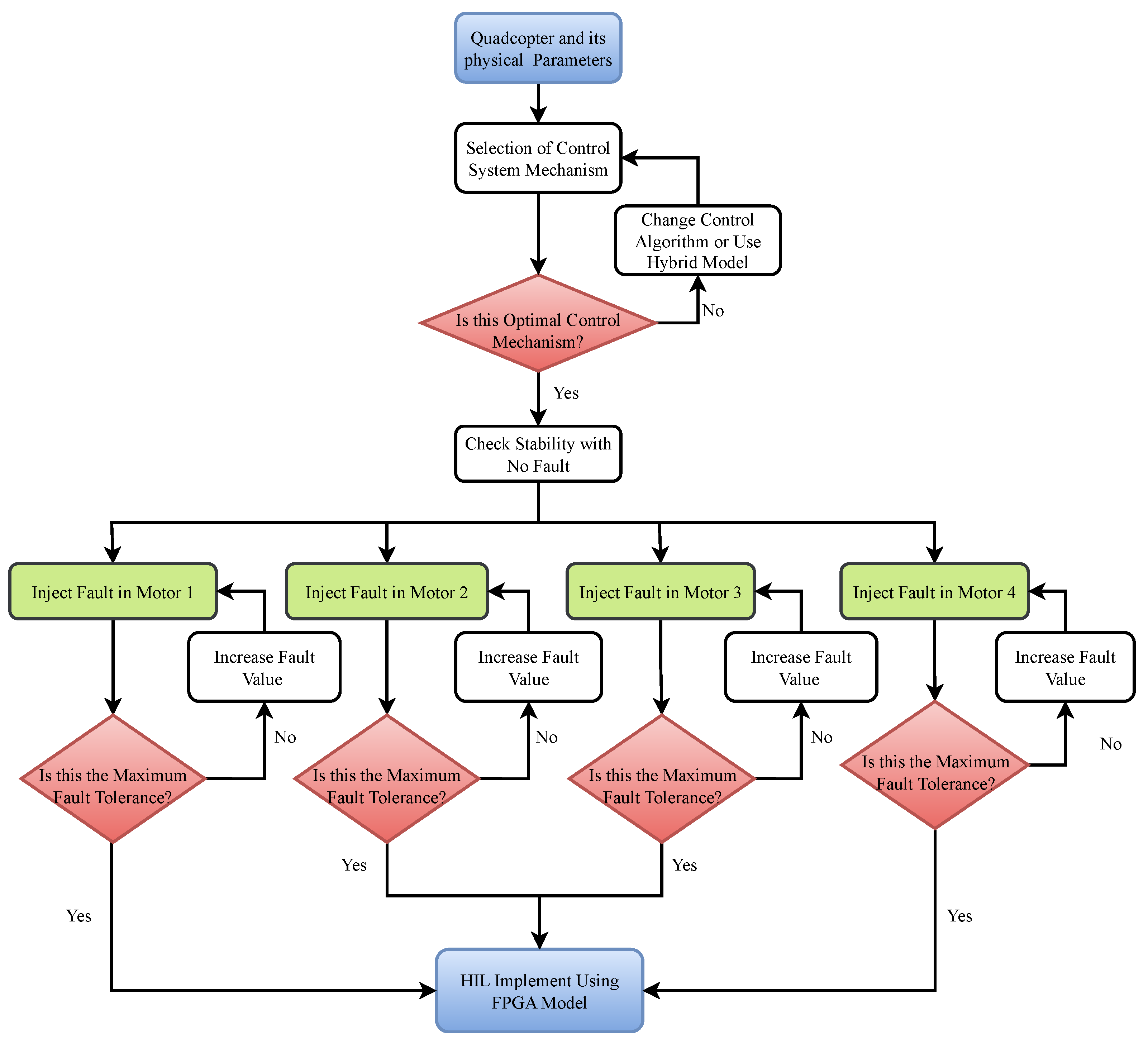
Figure 2 shows the flowchart of a methodological process to validate quadcopter UAV fault-tolerance control at each stage of a structured control system implementation. UAV has many types that depend on their size, type, and orientation style among fixed-wing and rotary-wing models, and hybrid designs. This work starts with selecting the quadcopter as a model and then selecting quadcopter’s physical attributes, including weight, thrust power usage, dynamic performance requirements, and system power needs.
The study employs integral back-stepping and sliding-mode control as its optimal control model because these methods demonstrate exceptional robustness in operating with uncertainties and system disturbances. The implemented control approaches deliver enhanced performance for stability tracking and trajectory control in conditions with faults.
The proposed FTC system is an optimal model, and then the quadcopter stability testing is carried out with no fault in any motor to create a baseline for the analyses during the fault. It is fundamental to test the UAV under optimal operating conditions before conducting fault evaluations and demonstrations of efficiency. A systematic fault-creating method is applied to the quadcopter motors to investigate how well the proposed controller handles these anomalies during evaluation.
A 10% fault is introduced to a solitary motor during the initial tests to monitor how the quadcopter system responds. The control system’s operation successfully addresses this minimal fault, which allows stable flight operations to persist. After this minimal fault, then we increase the fault by 20. During the 30% fault and then the 50% fault on any single motor, the proposed controller maintains flight stability during each test run. We have tested all the motors of the quadcopter one by one by applying 10%, 30%, and 50%. The analysis shows that the designed control system demonstrates superior reliability compared to previous findings, which reported maximum tolerance at 40% fault levels. This control system’s fault-tolerance capability is 50% while demonstrating superior advanced handling of faults in the motor. We increased the fault by more than 50%, but then the quadcopter lost its stability while flying.
After the maximum fault-tolerance level, we implemented the proposed control system on the FPGA (Field-Programmable Gate Array) hardware-in-the-loop (HIL) experiment to validate the results in real time. The HIL method enables the evaluation of how the control algorithm performs regarding computational speed as well as timing limitations and deployment reliability, as it operates in genuine hardware platforms. The implementation of this step bridges the theoretical validation into real-world use for fault-tolerant control systems, ensuring the system reliability of the actual quadcopter.
Two control loops are considered in quadcopter dynamics: one governs the rotating motion and the other governs the translational motion. Despite system failures, the quadcopter may retain stability and follow a desired trajectory thanks to the cooperation of both techniques. In the case of the NLDO-SMC for rotating motion and the IBS for translational motion in the fault-tolerant control system of a quadcopter UAV, Lyapunov stability is considered in the design and analysis of the proposed scheme.
Figure 3 presents the block diagram of the proposed quadcopter’s control system, which integrates advanced mechanisms with fault tolerance. The trajectory planner section provides actual and desired trajectory information. The active FTC section includes an integral back-stepping controller (IBSC), which regulates translational motion and generates signals for altitude and horizontal movement, and sliding-mode control (SMC) with a nonlinear disturbance observer (NL-DO) for rotational motion control, enhanced by an observer that predicts system uncertainties and external disturbances. A simulating actuator-fault block processes rotational control inputs, and the quadcopter model is running in the UAV section. This fault-tolerant control system ensures quadcopter attitude and position stability, mitigating disturbances and faults. The proposed technique is designed and evaluated using Lyapunov stability analysis. The Nexys A7 Artix-7 FPGA Trainer Board is used to build the active FTC part, while MATLAB/Simulink version R2023b is used to simulate the UAV model, trajectory planner, and actuator failures.

4.1. Integral Backstepping-Based Controller for Translational Motion Monitoring and Controlling

The translational control dynamics of quadcopter systems are modeled using three-dimensional Newton–Euler equations, with the rotor’s thrust forces serving as control inputs [28]. Backstepping, a recursive design approach, is effective for nonlinear systems like UAVs, as it stabilizes the system progressively [29]. Integral backstepping control (IBSC) builds upon traditional backstepping control to eliminate steady-state errors, enhance disturbance rejection, and ensure fault tolerance [30]. Specifically, if a motor fails, the integrated action adjusts the total thrust to maintain the quadcopter at the desired position. This design stabilizes the quadcopter’s translational motion.
The IBSC is designed to regulate the quadrotor’s translational motion. The position tracking error is defined as part of the IBSC design process, and then a virtual control rule for velocity dynamics is introduced. The IBSC cascades an integral action into the backstepping structure to cancel out steady-state tracking errors, which are typically caused by parameter uncertainties or persistent disturbances. The architecture exploits a recursive Lyapunov approach to the virtual controller synthesis, where each control signal update is obtained so that stability conditions are enforced at any recursion level, thus assuring ultimately global asymptotic convergence of the tracking errors. Through the selection of suitable stabilizing functions and gain settings, the control law guarantees Lyapunov stability at every stage. The IBSC mathematical design for the x-axis is discussed below.
x ˙ 2 = k x x 2 2 + u x 1 m u 1 x ˙ 1 = x 2
The derivative of the tracking error variable x is
ε ˙ 1 = x 2 x ˙ d 1
where x ˙ d 1 is the desired trajectory.
Lyapunov function V 1 ε 1 is used for stability and the derivative of this is
V ˙ 1 ε 1 = ε 1 x 2 x ˙ d 1
Since this form is commonly used in control theory, especially in Lyapunov-based stability analysis, we have selected it to support positive definiteness and its energy-like nature. A crucial need for demonstrating asymptotic stability in nonlinear control design is the derivation of a negative definite derivative, which is made possible by this function, which also guarantees that the system’s error dynamics stay confined.
To stabilize ε 1 , x 2 is used as control input which is equal to x ˙ d 1 κ 1 ε 1
Add x 2 value, in Equation (13)
V ˙ 1 ε 1 = κ 1 ε 1 2
For the second error state stabilization, α 1 x 1 is used
α 1 x 1 = x ˙ d 1 κ 1 ε 1
the second tracking-error variable for x 2 is
ε 2 = x 2 α 1 x 1 ε 2 = x 2 x ˙ d 1 + κ 1 ε 1
from Equation (13)
ε ˙ 1 = ε 2 κ 1 ε 1
Taking the derivative of Equation (16) and placing it in Equation (11), we get
ε 2 ˙ = k x x 2 2 + u x 1 m u 1 x ¨ d 1 + κ 1 ε ˙ 1
Select augmented Lyapunov function V a 1
V a 1 ε 1 , ε 2 = 1 2 ε 1 2 + ε 2 2
After derivative of V a 1 and values substitution, we get
V ˙ a 1 ε 1 , ε 2 = κ 1 ε 1 2 + ε 2 ε 1 k x x 2 2 + u x 1 m u 1 x ¨ d 1 + κ 1 ε ˙ 1
Finally, the control input u x is obtained as shown below
u 1 = m u x ( κ 2 ε 2 ε 1 + k x x 2 2 + x ¨ d 1 κ 1 ε ˙ 1 )
u x = m u 1 κ 2 ε 2 ε 1 + k x x 2 2 + x ¨ d 1 κ 1 x 2 x ˙ d 1
Putting it into Equation (20), the Lyapunov function becomes
V ˙ a 1 ε 1 , ε 2 = κ 1 ε 1 2 κ 2 ε 2 2
The negative Lyapunov function derivative in Equation (23) shows the proposed control system’s stability. The expressions for u y and u z are also derived using the same process as for u x , as shown in Equation (24) and Equation (25), respectively. The Lyapunov function derivatives are likewise negative, as seen in Equations (26) and (27), demonstrating the stability of the proposed system.
u y = m u 1 κ 4 ε 4 ε 3 + k y y 2 2 + y ¨ d 1 κ 3 y 2 y ˙ d 1
u z = m cos ϑ 1 cos φ 1 κ 6 ε 6 ε 5 + g + K z z 2 2 + z ¨ d 1 κ 5 z 2 z ˙ d 1
V ˙ a 2 ε 3 , ε 4 = κ 3 ε 3 2 κ 4 ε 4 2
V ˙ a 3 ε 5 , ε 6 = κ 5 ε 5 2 κ 6 ε 6 2

4.2. Nonlinear Disturbance Observer Sliding Mode (NLDO-SM)-Based Controller for Rotational Motion Monitoring and Controlling

The attitude dynamics of a quadcopter are also influenced by its angular orientation [31]. It may be analytically represented by Euler angles, which are roll ϕ , pitch θ , and yaw ψ , as per Euler’s equations of rotational motion [32]. These dynamics describe the quadcopter’s rotation around its center of mass. The rotational dynamics are determined by the torques that the motors supply [33]. As SMC for the attitude tracking and controlling, an NL-DO is introduced to estimate unmeasured states and actuator faults. The sliding surface is expressed as a function of attitude error and its derivative to guide the system trajectory towards a fault-tolerant equilibrium manifold. A piecewise-continuous control law, designing a finite-time convergent system onto this surface, ensures immunity along matched disturbances and model errors. Furthermore, the SMC design for ψ appears as follows:
ψ ˙ 1 = ψ 2 ψ ˙ 2 = a 5 ψ 2 φ 2 K ψ ψ 2 2 + b 3 u 4
The tracking-error variable for ψ 1 is
ε ψ = ψ 1 ψ d 1
After the derivative, we get
ε ˙ ψ = ψ 2 ψ ˙ d 1
Selection of a sliding surface s 5 :
s 6 = d d t ε ψ + η 6 ε ψ n 1 , n = 2
s 6 = ε ˙ ψ + η 6 ε ψ
Put the value of ε ˙ ψ from Equation (30) in Equation (32)
s 6 = ψ 2 ψ ˙ d 1 + η 6 ε ψ
Further, the derivative of s 6 is
s ˙ 6 = ψ ˙ 2 ψ ¨ d 1 + η 6 ε ˙ ψ
putting the value of ψ ˙ 2
s ˙ 6 = a 5 ψ 2 φ 2 K ψ ψ 2 2 + b 3 u 4 ψ ¨ d 1 + η 6 ε ˙ ψ
The sliding surface is set to zero in developing SMC, s ˙ 6 = 0 . Equation (38) shows the switching control component, and Equation (37) shows the control input of a continuous control law.
a 5 ψ 2 φ 2 K ψ ψ 2 2 + b 3 u 4 ψ ¨ d 1 + η 6 ε ˙ ψ = 0
u 4 = 1 b 3 ( a 5 ψ 2 φ 2 + K ψ ψ 2 2 + ψ ¨ d 1 η 6 ε ˙ ψ )
u 4 s w = ζ 11 sign ( s 6 ) ζ 12 s 6
After adding u 4 s w to u 4 , we get
u 4 = 1 b 3 ( ζ 11 sign ( s 6 ) ζ 12 s 6 a 5 ψ 2 φ 2 + K ψ ψ 2 2 + ψ ¨ d 1 η 6 ε ˙ ψ )
Similarly, φ and θ have their SMC designs determined, and the relevant mathematical forms are shown in Equations (40) and (41), respectively.
u 2 = 1 b 1 ζ 7 sign ( s 4 ) ζ 8 s 4 a 1 ψ 2 θ 2 a 2 Ω ¯ θ 2 + K φ φ 2 2 + φ ¨ d 1 η 4 ε ˙ φ
u 3 = 1 b 2 ζ 9 sign ( s 5 ) ζ 10 s 5 a 3 ψ 2 φ 2 a 4 Ω ¯ φ 2 + K θ θ 2 2 + θ ¨ d 1 η 5 ε ˙ θ
In the mathematical form of NLDO-SMC, the constant values are given in (Table 1).
To direct the quadcopter toward a sliding surface while maintaining stability is the aim of the sliding-mode control law [34]. The Lyapunov function, which is the derivative of the squared sliding surface, needs to be negative to remain stable [35]. The Lyapunov function can be decreased by lowering rotational errors and stabilizing the system with a control rule. Based on the observer’s assessment of the system’s states or flaws, control input is adjusted. A Lyapunov-based approach, which ensures boundedness and asymptotic convergence of estimation errors, may be used to construct the observer [36].
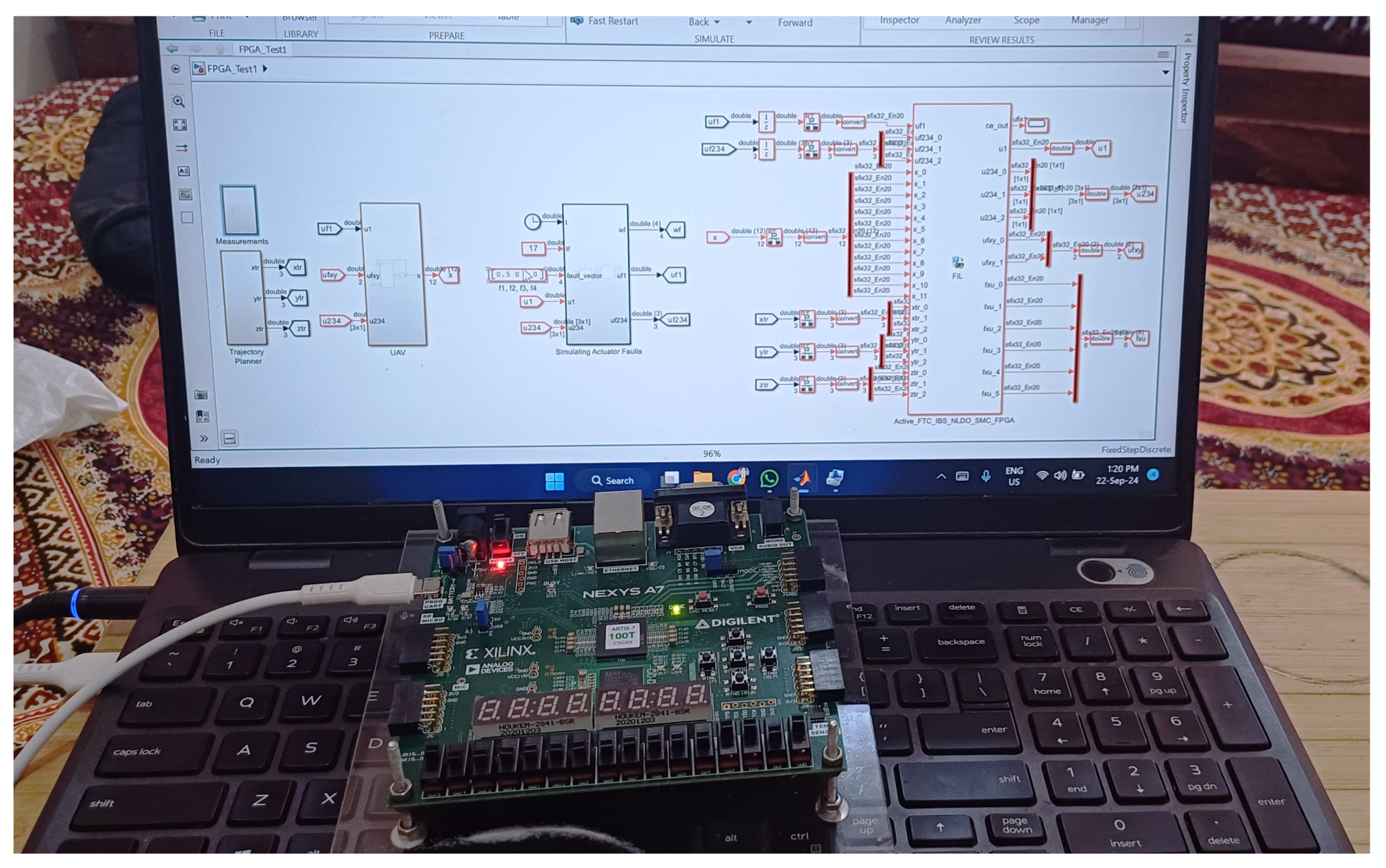
Figure 4 illustrates the actual hardware configuration used in this experiment. The Nexys A7 board, a powerful platform built on Xilinx’s Artix-7 Field-Programmable Gate Array (FPGA), is used to implement the designed control system model. The proposed control system is implemented on the FPGA board, and MATLAB/Simulink is used to run the quadcopter model, trajectory planner, and simulated fault actuator in order to verify the experimental findings.
In the case of model translation, the hardware description language (HDL) Coder is called, which generates Verilog HDL code, while Xilinx Vivado compiles to create a bitstream (.bit) file. The .bit file then gets downloaded to the FPGA device using the MATLAB/Simulink FPGA-in-the-Loop (FIL) wizard. The suggested controller requires real-time implementation. The various inherent nonlinear structure of the disturbance observer and the complexity of fault compensation means that the algorithm is computationally demanding. However, parallel processing of the FPGA offers significant improvement in performance and removes computer overhead, as compared to computer-based implementations. The FPGA synthesis performed in Xilinx Vivado uses such hardware resources as:
  • Look-up Tables: 31,800;
  • Block RAMs used: 26BRAM;
  • Number of Flip Flops: 4998;
  • Digital signal-processing blocks used: 240.

5. Results

This section presents the results of the FTC system for a quadcopter and evaluates the control system for a range of faulty conditions during operation. The performance of the proposed controller is verified in both simulation-based and real-time FPGA hardware implementation experiments. The system’s resilience and adaptability are determined by observing its performance under systematic motor failures. The main performance indicators are trajectory analysis in coordinate systems and 3D, roll, pitch, and yaw angles as well as linear and angular velocities confirm its robustness. A critical aspect of the analysis is the system’s ability to recover from motor faults and to continue operating smoothly. In addition, the implementation of the proposed FTC on FPGA-based hardware also increases its practical applicability by validating its real-time execution efficiency. Overall, the study proves that the developed fault-tolerant control technique will greatly increase quadcopter reliability and constitute a desirable solution for UAV applications in such environments.
First, we allow the quadcopter to follow a trajectory while no motor fault acts as a baseline—the desired trajectory for the remainder of our study as shown in Figure 5. The desired path along the x-, y-, and z-axes is shown by the green, rust, and yellow lines, respectively. For the first ten seconds, the trajectory x d stays at zero. After that, it ascends linearly until the twentieth second, remains constant for the next ten seconds, and then drops linearly until the forty second. Up until the tenth second, y d climbs linearly; after that, it stays constant for the following ten seconds; after that, it declines linearly until the thirty-second mark; and finally, it stays constant until the forty-second mark. From the starting position until the 12th second, z d grows linearly; after that, it stays constant until the 40th second.

5.1. Quadcopter Trajectory Under Various Faults on Motor 1 of the Quadcopter

The above figures illustrate the trajectories followed by the quadcopter under different faults on motor 1 with a proposed control model using both simulation-based and FPGA hardware-based methods. To assess the stability and tracking performance of the system, faults are injected incrementally (10%, 30%, and 50%) to motor 1 of the quadcopter. Considering a 10% fault occurred on motor 1, the simulation-based trajectory shown in Figure 6 and hardware-based trajectory in Figure 7 are closest to the desired trajectories across all x, y, z directions, which proves that there is a successful fault tolerance. Similarly, Figure 8 (simulation) and Figure 9 (hardware) show that consistent trajectory tracking is seen for a 30% fault for motor 1 with minor deviation from the desired paths at the initial point only, which is due to the parameter selections. The quadcopter remains stable and accurately follows the desired trajectories even when they are subjected to a 50% fault on motor 1, as can be seen from Figure 10 for simulation and Figure 11 for hardware-based analysis. These results confirm the robustness of this proposed controller based on integral back-stepping control and nonlinear observer-based sliding-mode control for translational and rotational motion. By using the integral back-stepping control to handle system dynamics and disturbances, and the nonlinear sliding-mode observer to improve fault compensation by estimating unmeasured states and providing the well-known uncertainty mitigation ability, the proposed FTC efficiently handles system dynamics and disturbances, and improves fault compensation for up to 50% malfunction of the quadcopter motor. This combination, by keeping the quadcopter aligned with the actual and desired trajectories, proves to facilitate stable and precise tracking of the actual trajectories under all tested levels of fault.

5.2. Quadcopter Trajectory Under Various Faults on Motor 2 of the Quadcopter

The trajectories followed by the quadcopter under various fault conditions on motor 2 are illustrated above, demonstrating simulation-based and FPGA hardware-based results. In the presence of a 10% fault on motor 2, the quadcopter accurately tracks the desired trajectories in the x, y, and z directions, as shown by the simulation-based results in Figure 12 and the hardware-based results in Figure 13. Similarly, when subjected to a 30% fault on motor 2, the simulation-based trajectory in Figure 14 and the hardware-based trajectory in Figure 15 demonstrate negligible deviation from the desired path, highlighting the effectiveness of the proposed control system. For a more severe fault of 50% on motor 2, the quadcopter still maintains stability and tracks the desired trajectories with high precision, as observed in the simulation-based results in Figure 16 and the hardware-based results in Figure 17. These results confirm that the quadcopter consistently follows the desired trajectories in all x, y, and z directions under different fault conditions, validating the robustness and reliability of the proposed control system. The findings also align with the trajectories depicted in the previous figure, emphasizing the fault-tolerance capability of the control approach.

5.3. Quadcopter Trajectory Under Various Faults on Motor 3 of the Quadcopter

The above figures present the quadcopter’s trajectories under different fault scenarios injected into motor 3, comparing simulation-based and FPGA hardware-based outcomes. With a 10% fault on motor 3, the quadcopter effectively follows the desired paths along the x, y, and z axes, as evidenced by the simulation results in Figure 18 and the hardware results in Figure 19. Likewise, when facing a 30% fault, the simulation trajectory in Figure 20 and the hardware trajectory in Figure 21 exhibit only negligible deviations from the desired path, demonstrating the efficacy of the proposed control system. Even under a severe 50% fault on motor 3, the quadcopter remains stable and accurately tracks the desired trajectory, as shown by the simulation results in Figure 22 and the hardware results in Figure 23. These results affirm the quadcopter’s ability to maintain accurate trajectory tracking under varying fault levels, proving the robustness and dependability of the proposed control solution.

5.4. Quadcopter Trajectory Under Various Faults on Motor 4 of the Quadcopter

The quadcopter’s trajectories under various motor 4 failure scenarios are shown in the above figures, which contrasts simulation-based with FPGA hardware-based performance. The simulation and hardware results show that the quadcopter successfully maintains the intended trajectories along the x, y, and z axes, even with a 10% fault on motor 4, as shown in Figure 24 and Figure 25, respectively. When the fault level increases to 30%, both the simulation trajectory in Figure 26 and the hardware trajectory in Figure 27 show minimal deviation from the target path, proving the control system’s effectiveness. Even with a 50% fault, the quadcopter remains stable and accurately tracks the desired path, as shown in Figure 28 for simulation and Figure 29 for hardware. These results confirm the quadcopter’s ability to follow the designated trajectories under different fault scenarios, underscoring the robustness and reliability of the proposed control framework. Moreover, the findings are consistent with the previous figure, emphasizing the system’s strong fault-tolerance capabilities.

5.5. Quadcopter 3D Track Followed Under Various Faults on Motor 1 of the Quadcopter

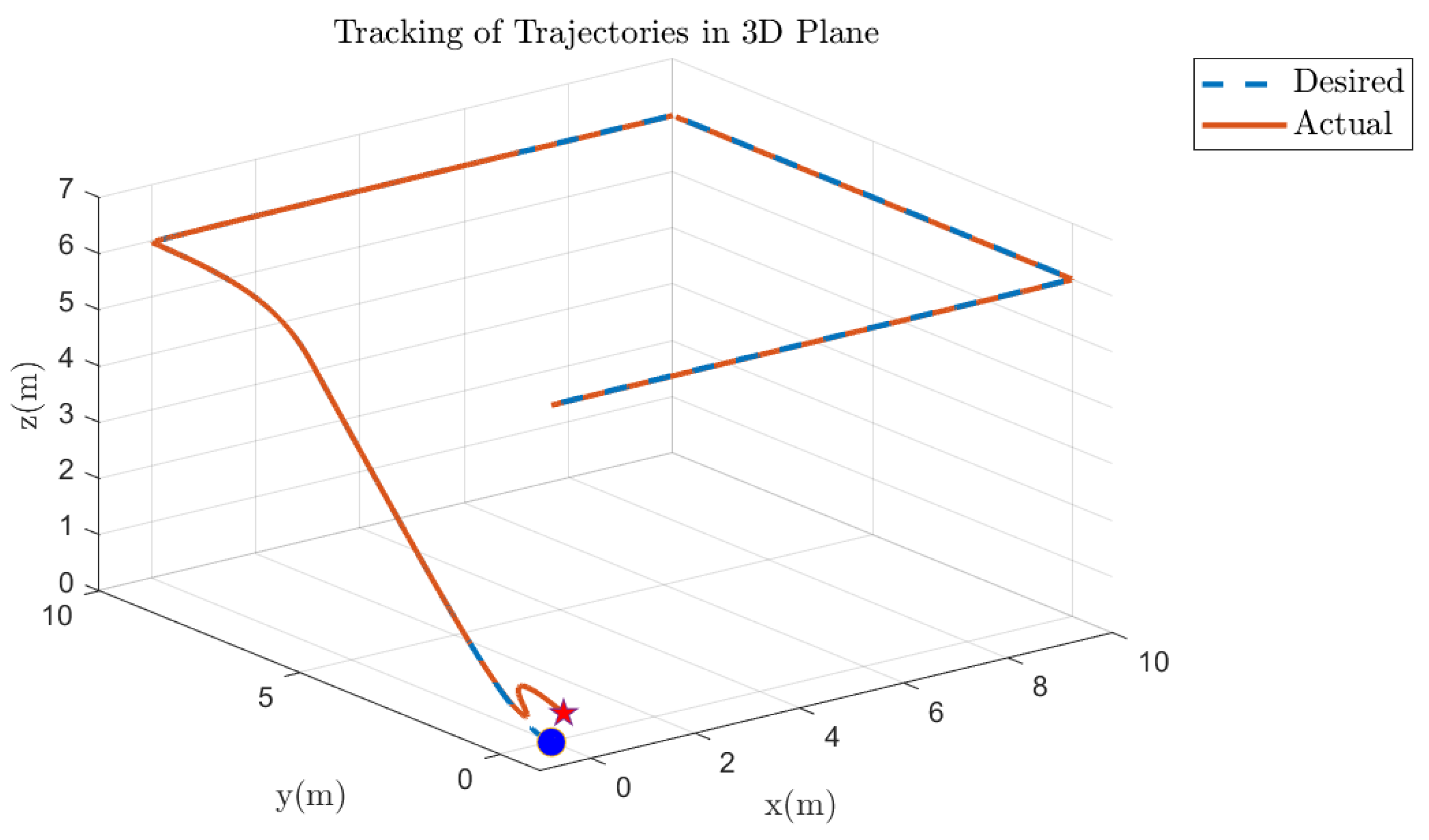
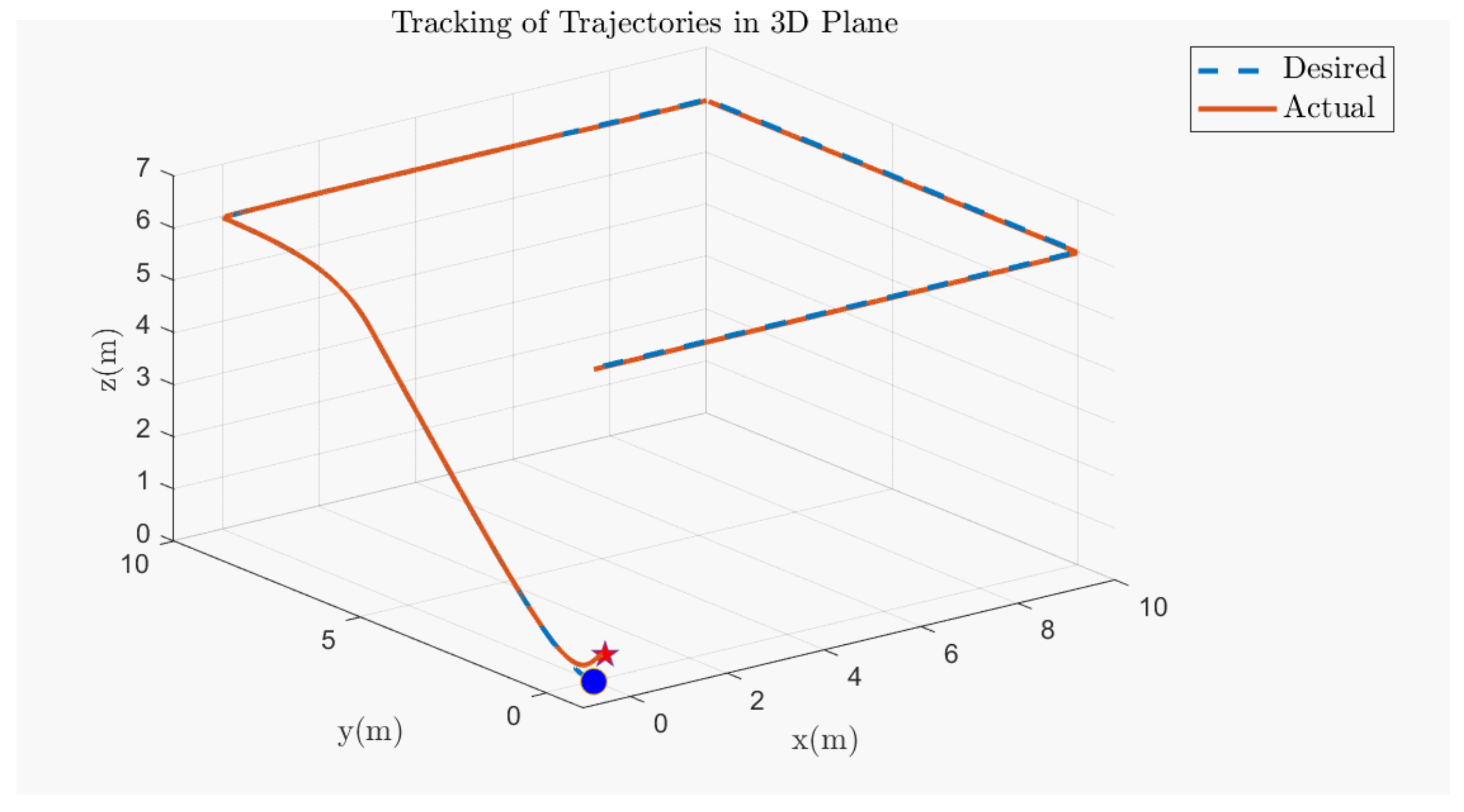
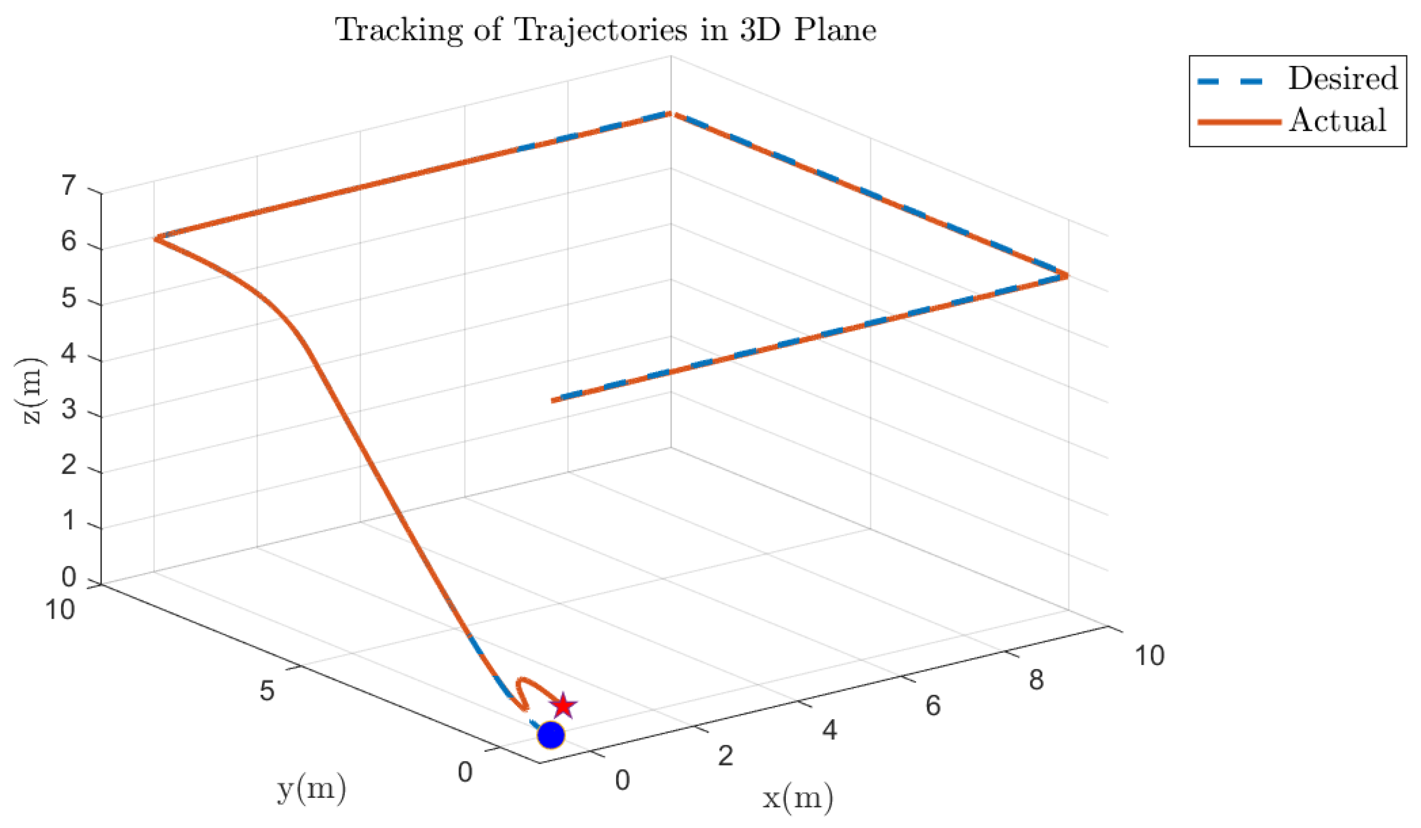
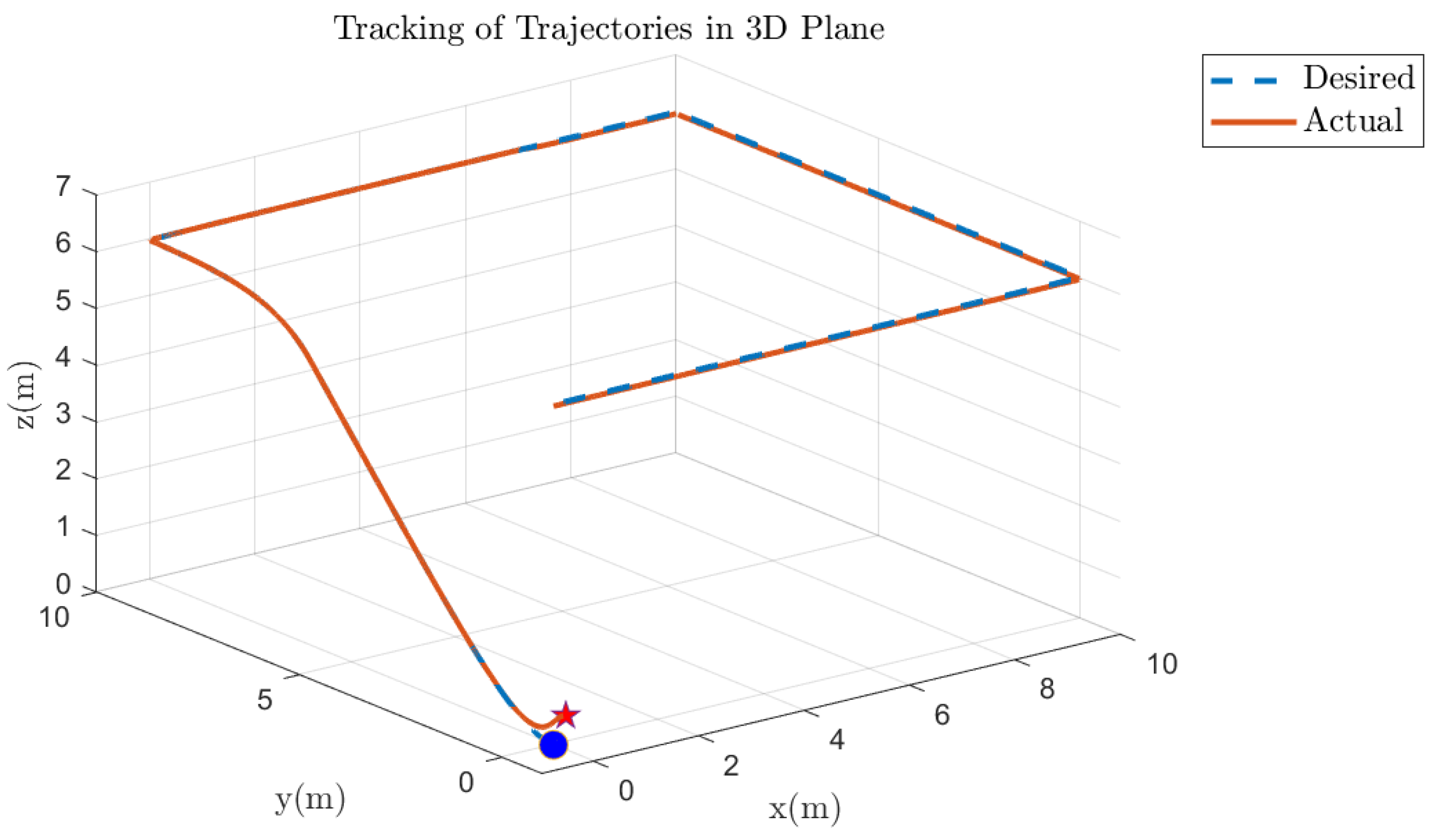
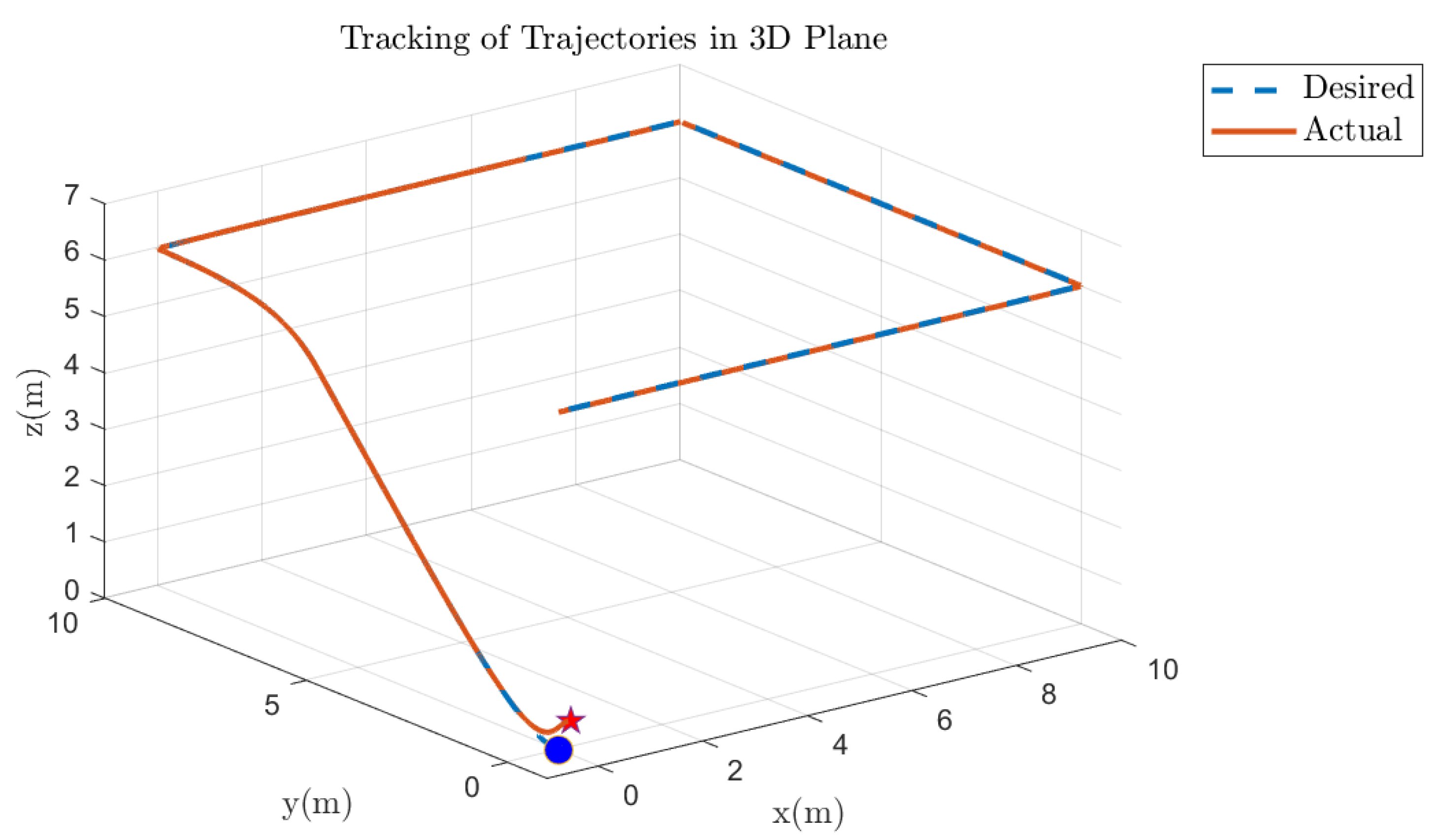
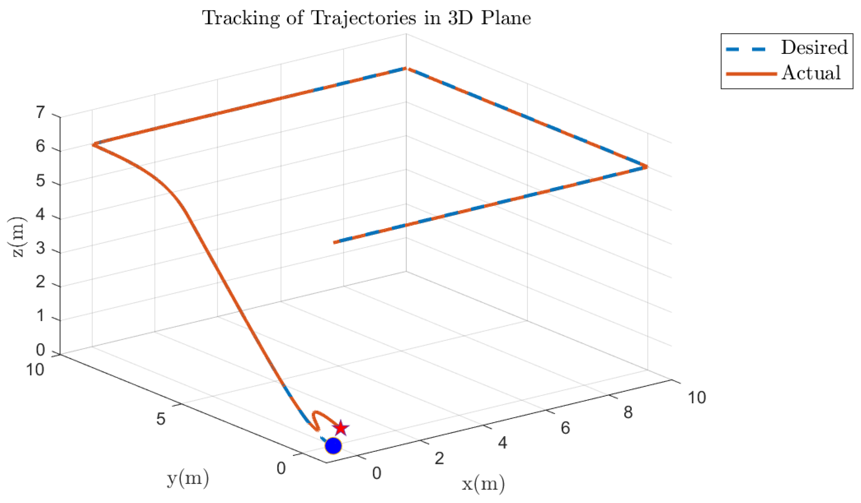
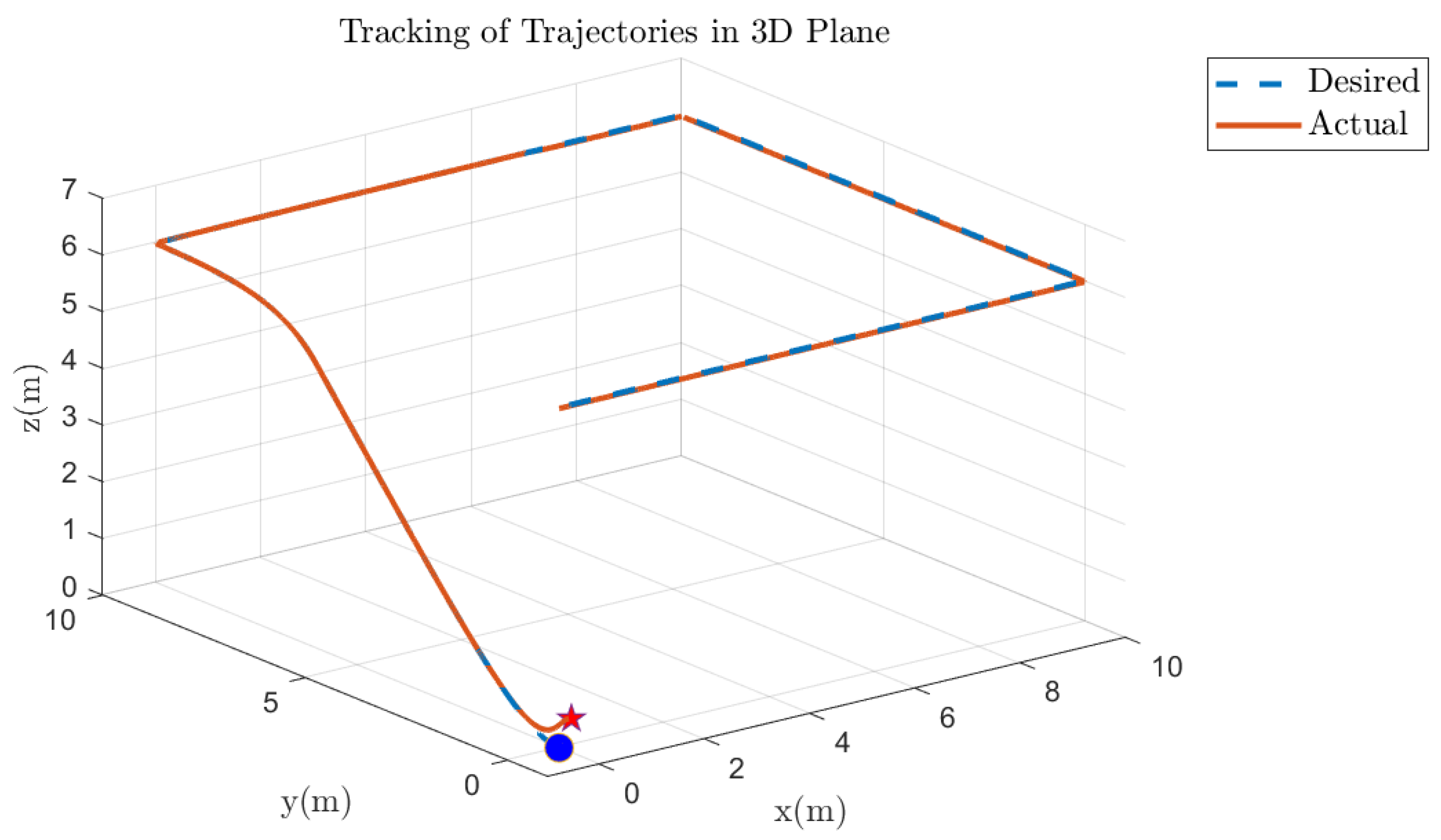
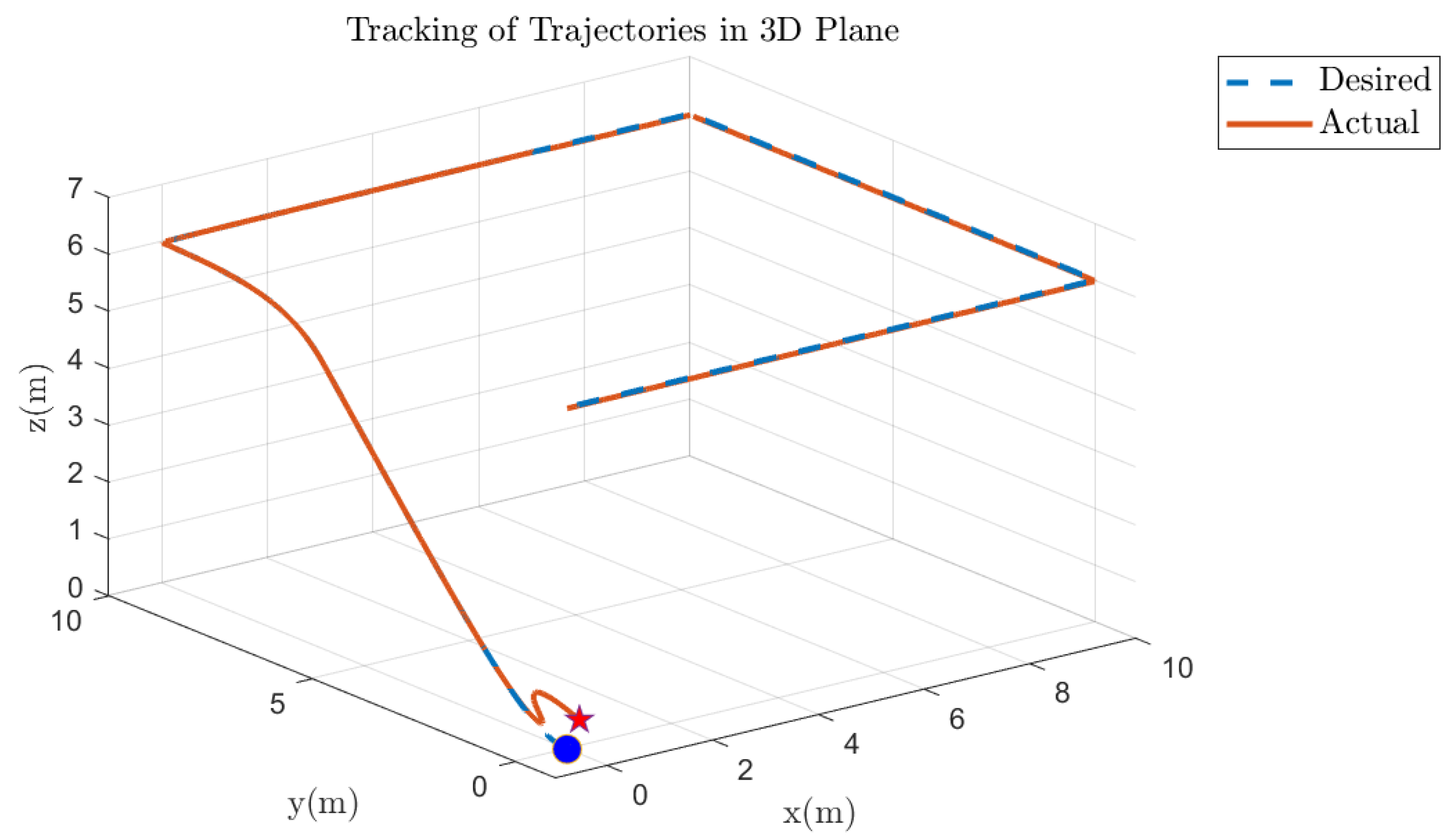
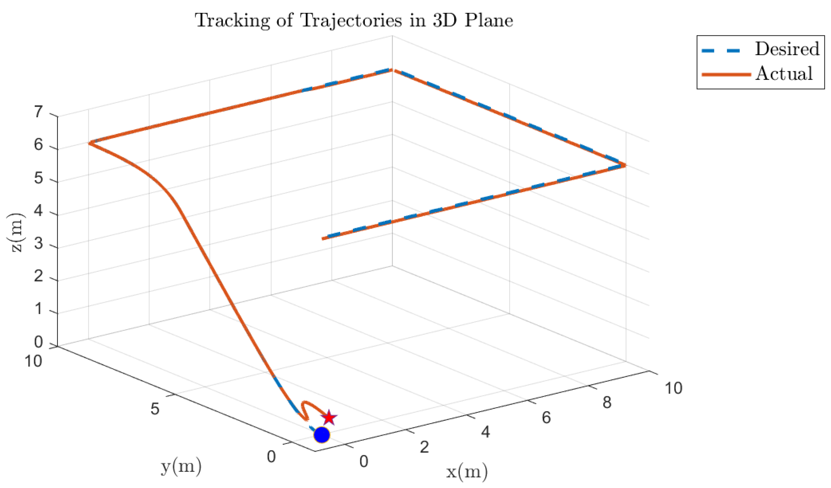
The above figures show the 3D plane trajectory-tracking performance of the quadcopter via simulation-based results and FPGA hardware results under different fault levels on motor 1. Simulation-based results of a 10% fault on motor 1 are shown in Figure 30, where the actual trajectory follows the desired trajectory, with residual deviations showing the effectiveness of the fault-tolerant control system. The corresponding FPGA hardware-based results for the same fault are shown in Figure 31, which indicates a similar trajectory with minimal initial deviations that are corrected quickly. Subsequently, the same 10% fault was individually injected into motors 2, 3, and 4, and the results obtained were identical to those observed with a 10% fault on motor 1. In Figure 32, we present the simulation results under a 30% fault on motor 1, where the system remains stable and approximately tracks the desired trajectory during the early stages. The same fault condition is largely confirmed by the hardware-based results in Figure 33, which show that controller performance in real-world hardware is fairly close to simulation results. Similarly, introducing a 30% fault into motors 2, 3, and 4, one at a time, yields identical outcomes to those obtained with a 30% fault in motor 1. Figure 34 illustrates the simulation-based 3D trajectory tracking under a severe 50% failure on motor 1. The results demonstrate effective stabilization and convergence to the desired path. FPGA hardware-based results for a 50% fault are shown in Figure 35 and a similar deviation and correction pattern as in the simulations is observed. Similarly, a 50% fault on the other motors produced the same results. In all cases, the error for the actual (orange) trajectory versus the desired (blue) trajectory shows the controller can withstand up to 50% fault in motor 1 and effectively keep the quadcopter stable while following the desired path. This validates the robustness and reliability of the proposed fault-tolerant control mechanism under various motor failure conditions.

5.6. Quadcopter 3D Track Followed Under Various Faults on Other Motors of the Quadcopter

The above figures show the 3D trajectory-tracking performance of a quadcopter that suffers from fault levels on motors 2, 3, and 4, and compares the simulations’ predicted values with measured ones through an FPGA-based hardware platform. The simulation-based results for a 10% fault on motor 2 are shown in Figure 36, where the actual trajectory is almost identical to the desired trajectory with only small initial deviations and quick stabilization by the proposed fault-tolerant controller. The corresponding results from the FPGA hardware-based implementation of the same fault level as shown in Figure 37 also have similar performance, confirming that the controller is effective in both simulation and real-world implementations. Furthermore, injecting a 10% fault on the other motors 1, 3, and 4 also yielded identical results, consistent with these tracking graphs. Simulation-based results for a 30% fault on motor 3 in Figure 38 demonstrate that the trajectory followed the desired path and quickly converged because of the system stability. The hardware-based results, shown in Figure 39, have a similar response to the simulation results for the 30% fault on motor 3, and the system effectively followed the desired trajectory in 3D plane. Similarly, we injected the same 30% fault on motors 1, 2, and 4, which also yielded identical results, consistent with the tracking graphs in the 3D plane. Figure 40 shows that the simulation-based trajectory tracking in 3D plane with a 50% fault on motor 4 shows more evident deviations off of the onset, but the trajectory eventually stabilizes to line up with the desired trajectory due to the proposed controller’s efficiency. Figure 41 presents the hardware-based results for a 50% failure on motor 4, demonstrating stabilized performance consistent with the simulations. Similar results were obtained in the 3D plane for 50% defects on the other motors. The proposed FTC mechanism exhibits robustness to up to 50% fault on any motor, enabling the quadcopter to maintain stability and track the desired path despite faults. This is evident from the desired trajectory (blue curve) and actual trajectories (orange curve) for all fault scenarios.

5.7. Quadcopter System Orientation Under Various Faults on the Motor of the Quadcopter

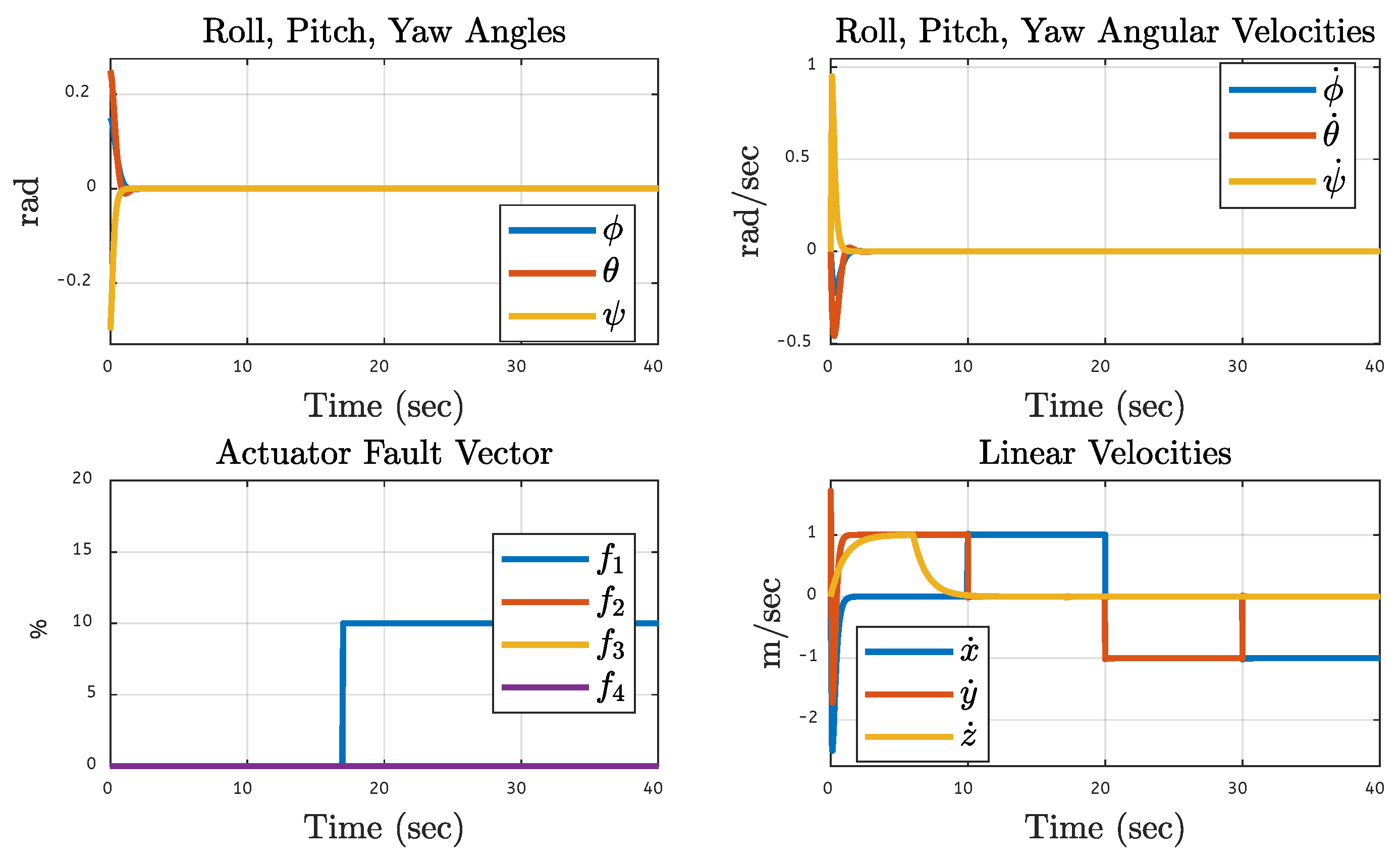
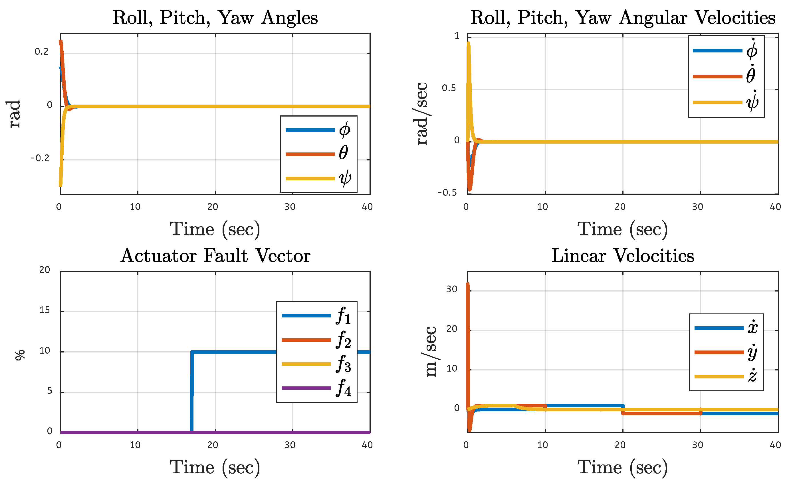
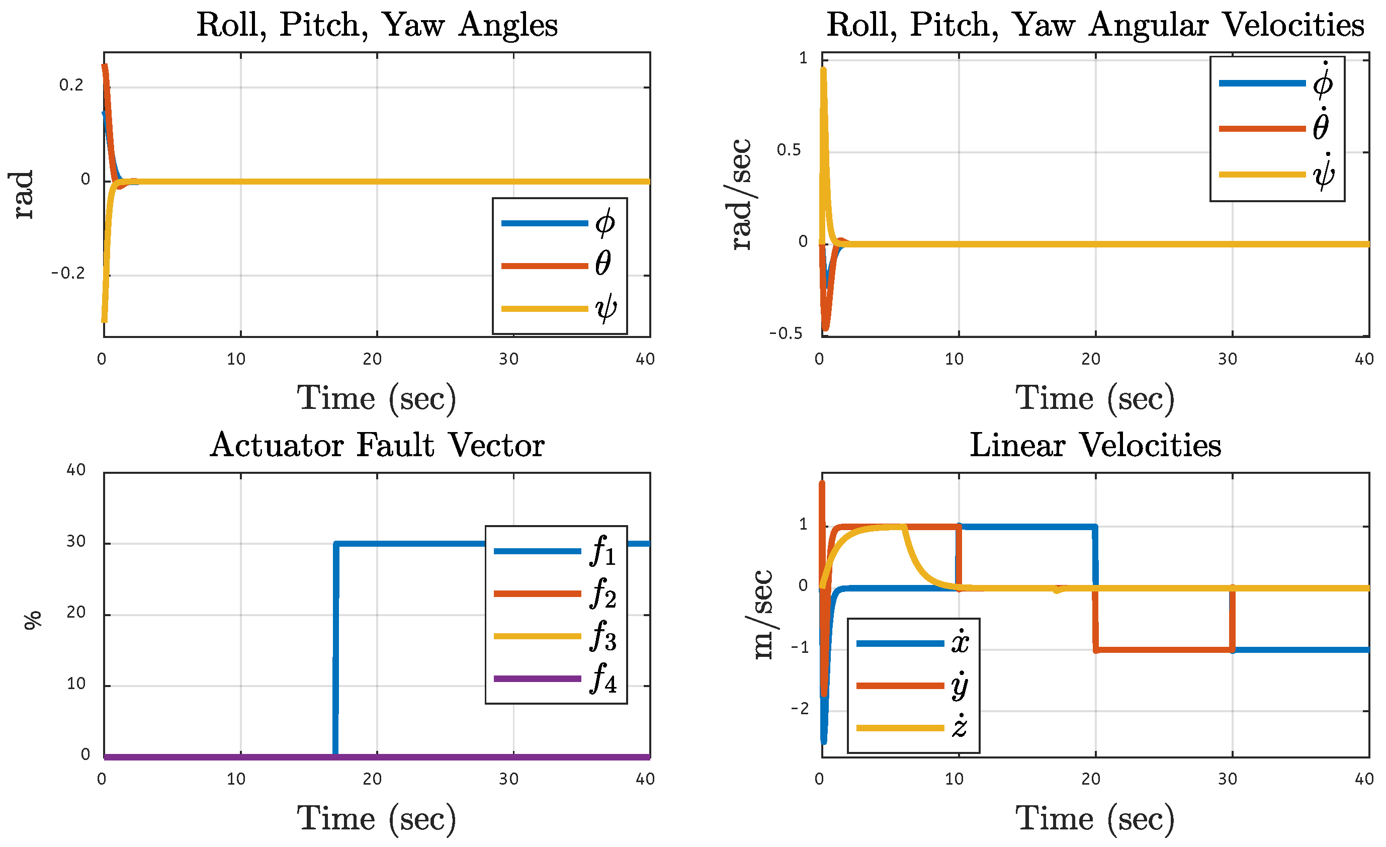
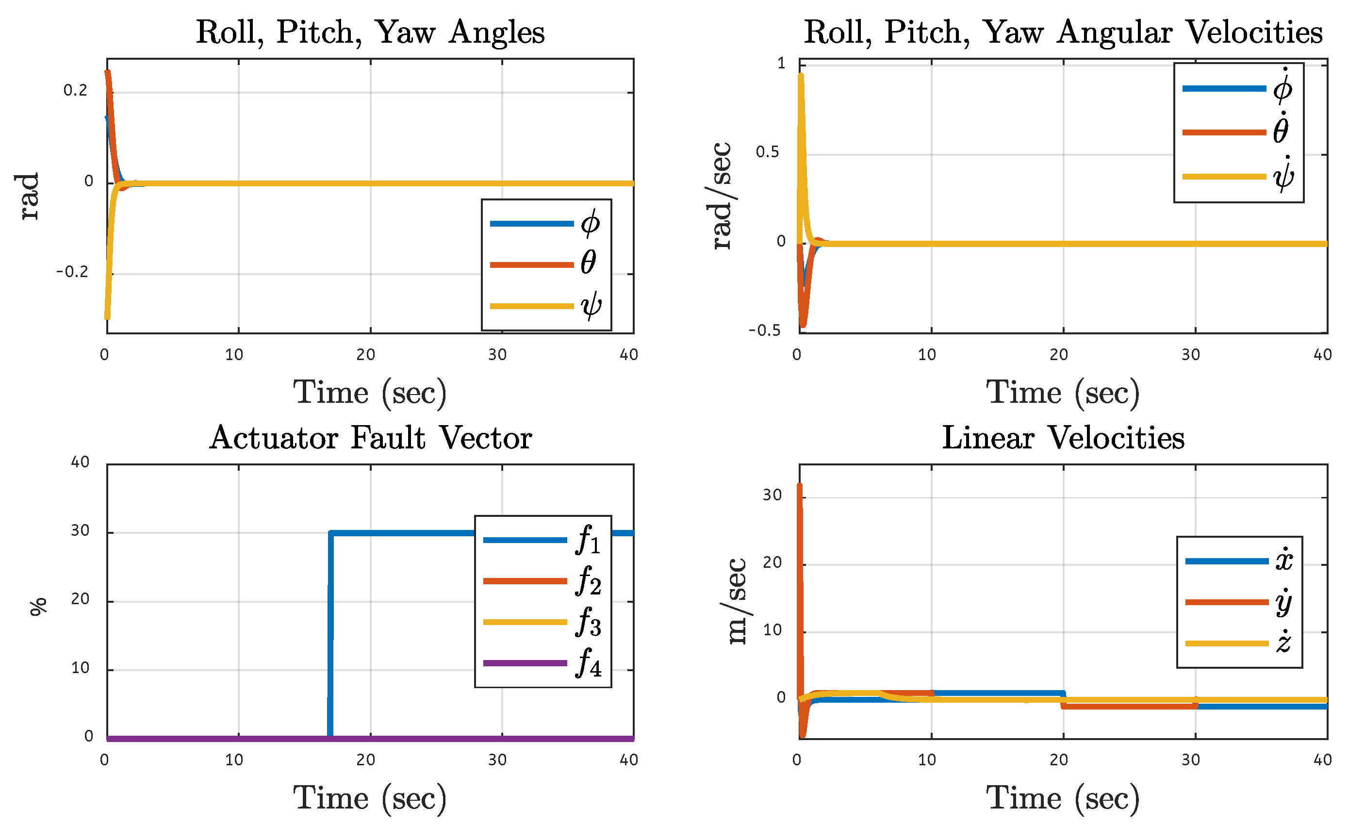
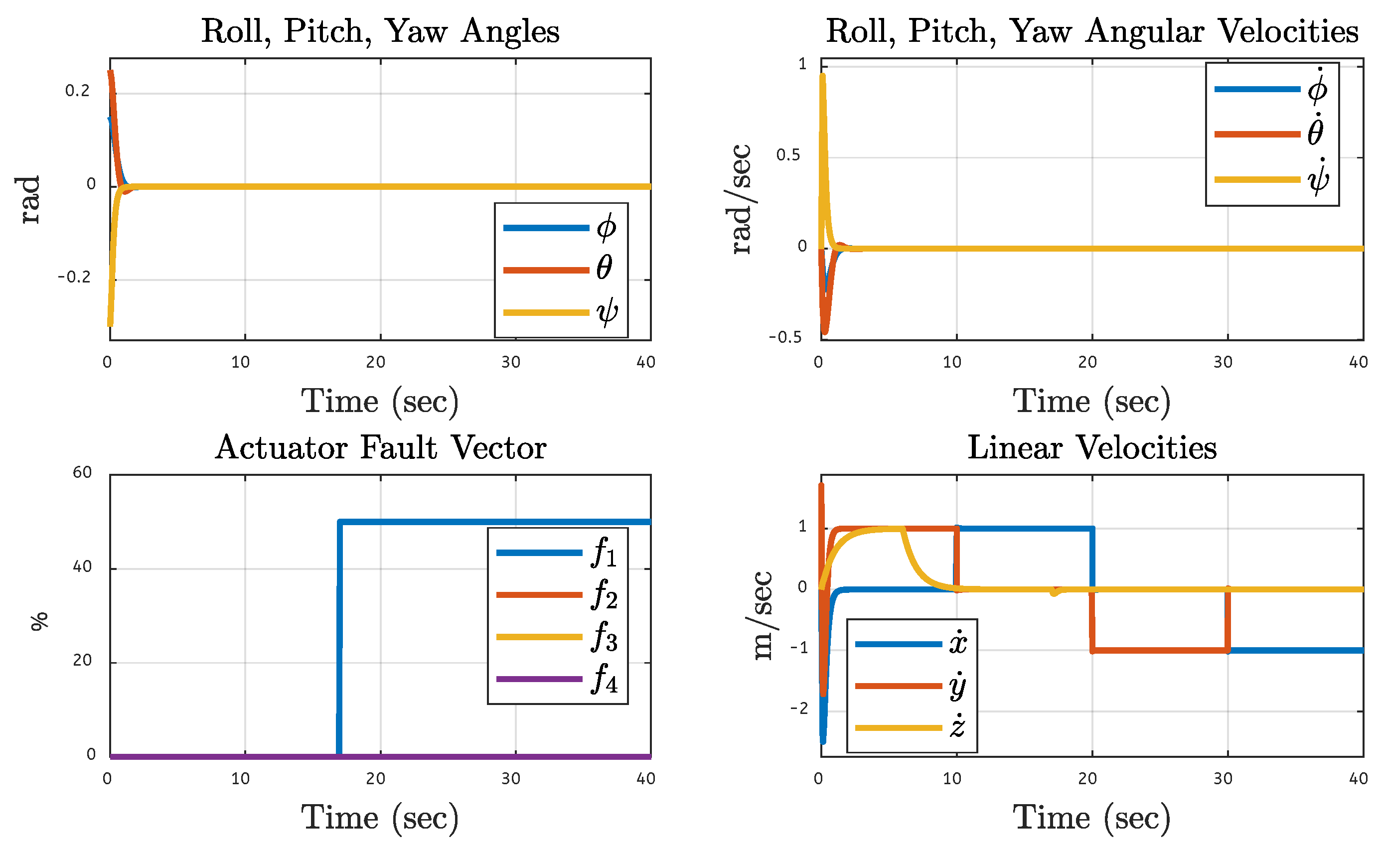
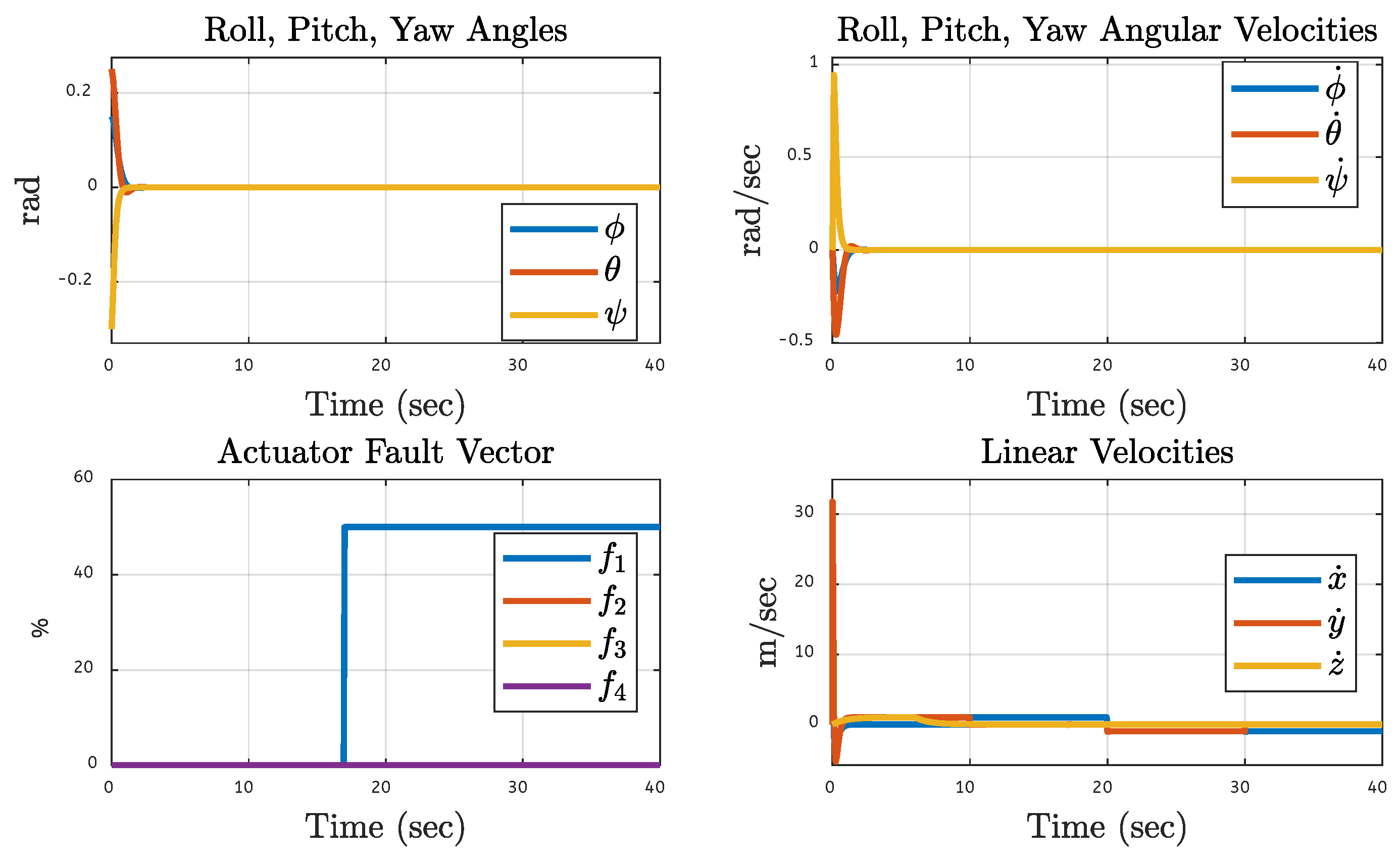
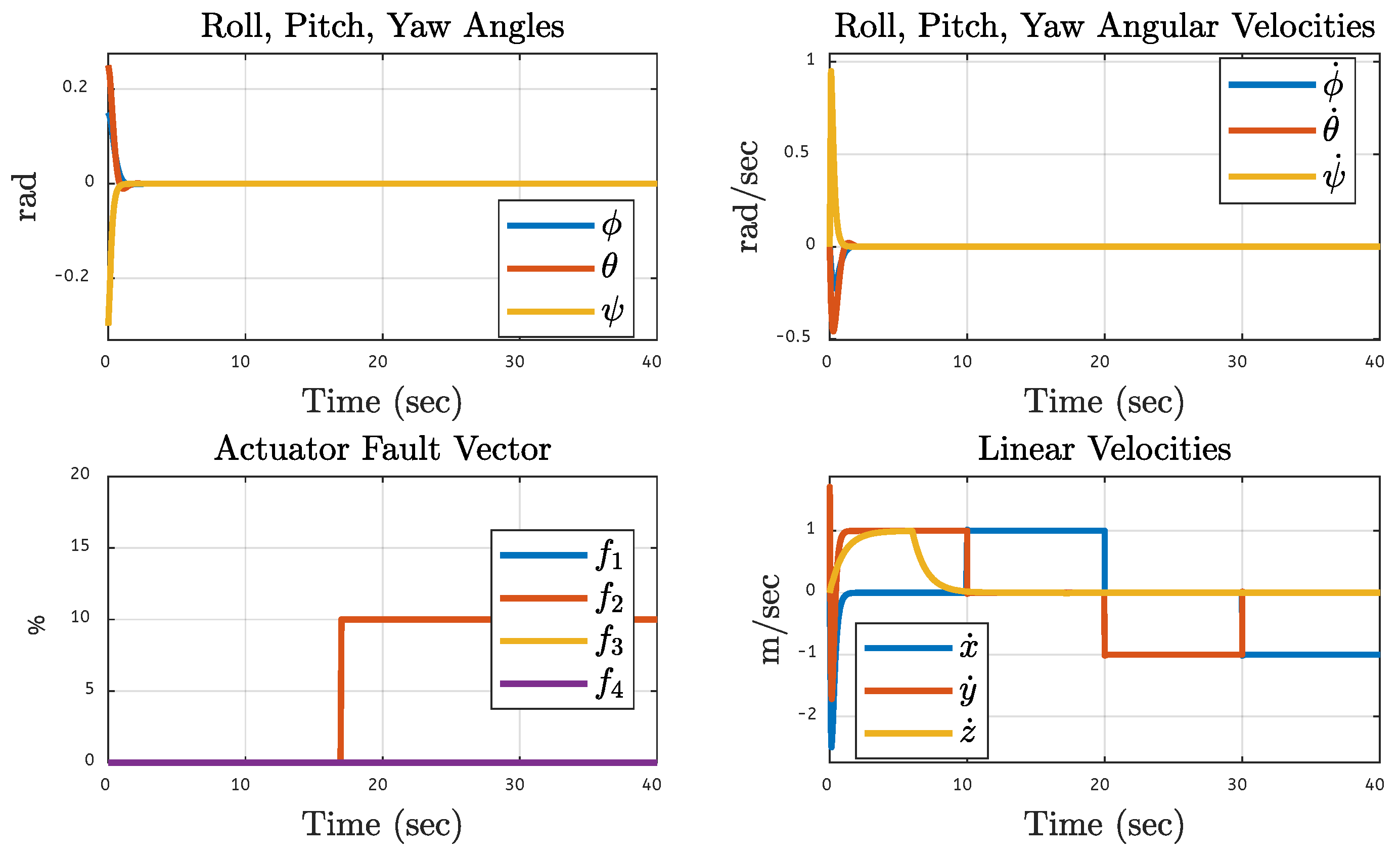
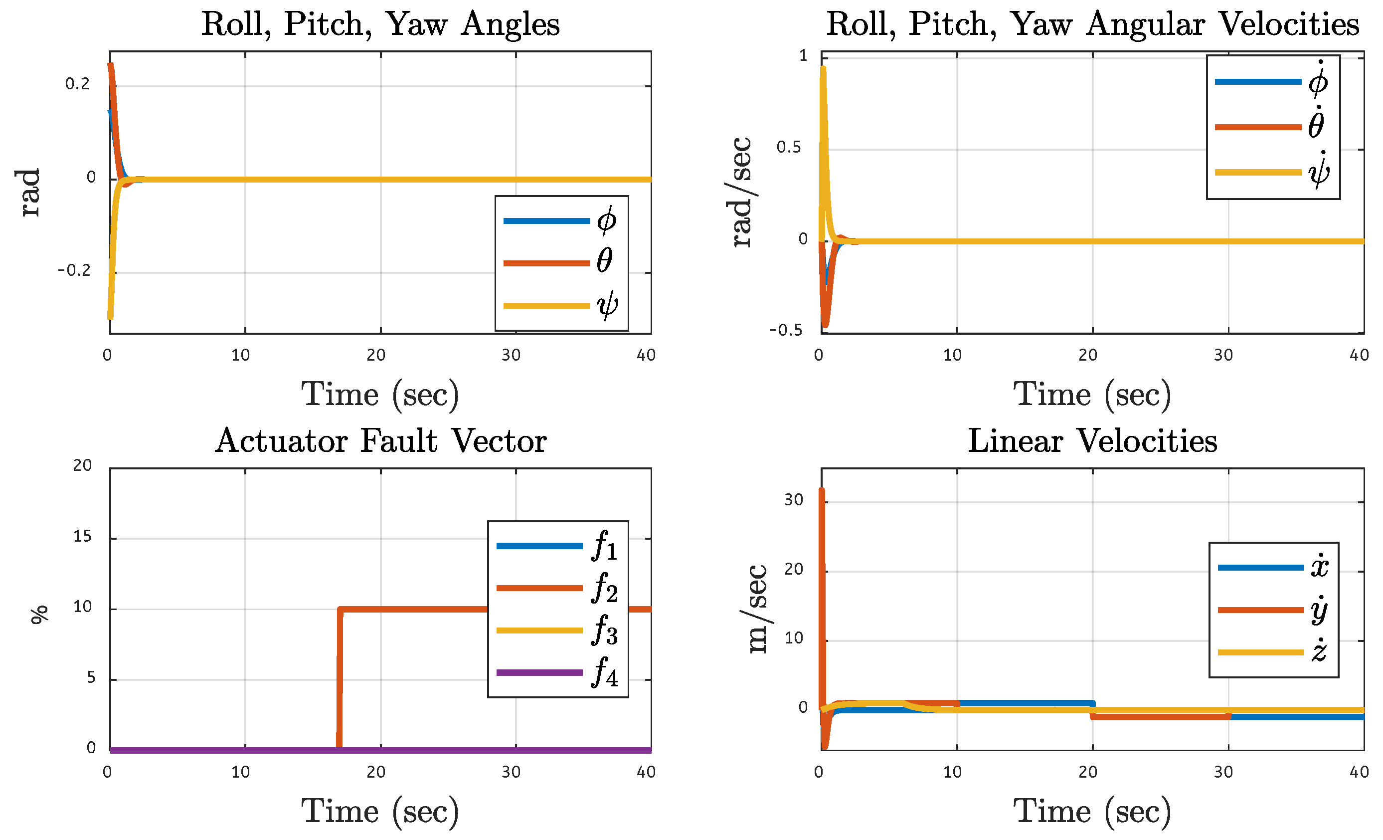
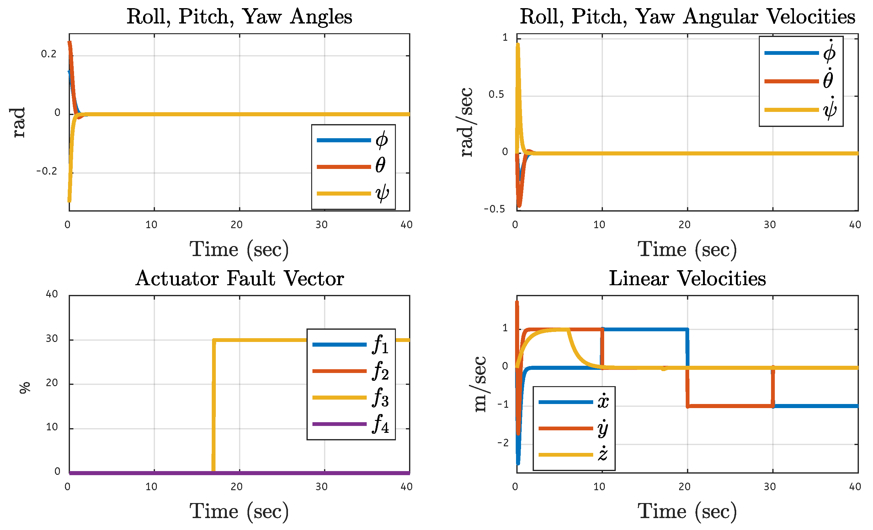
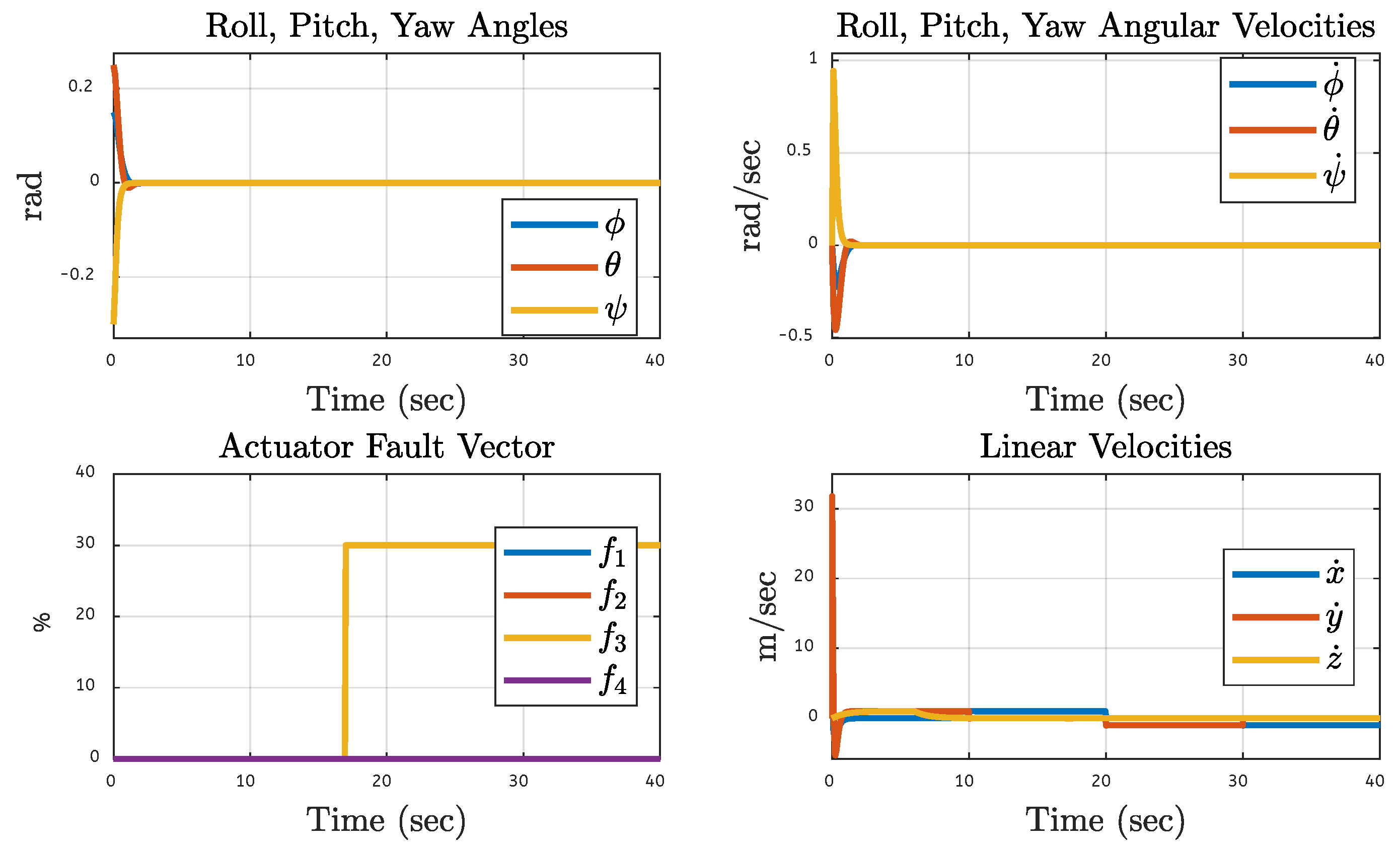
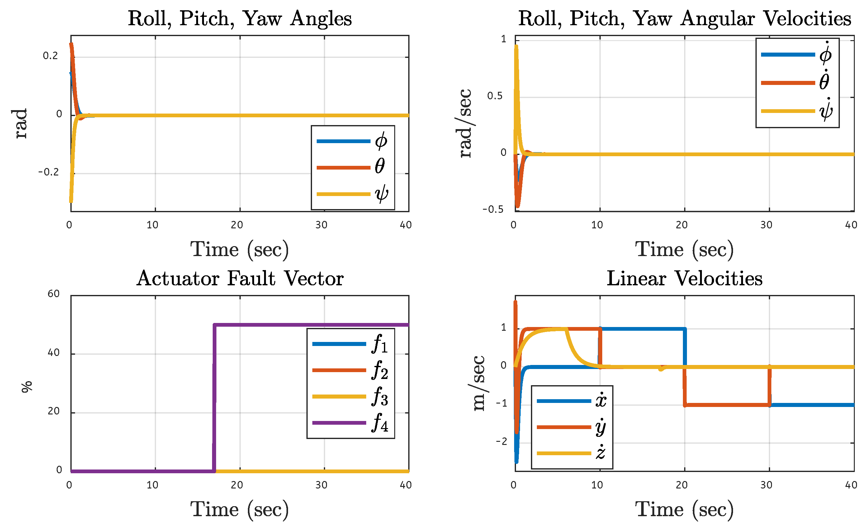
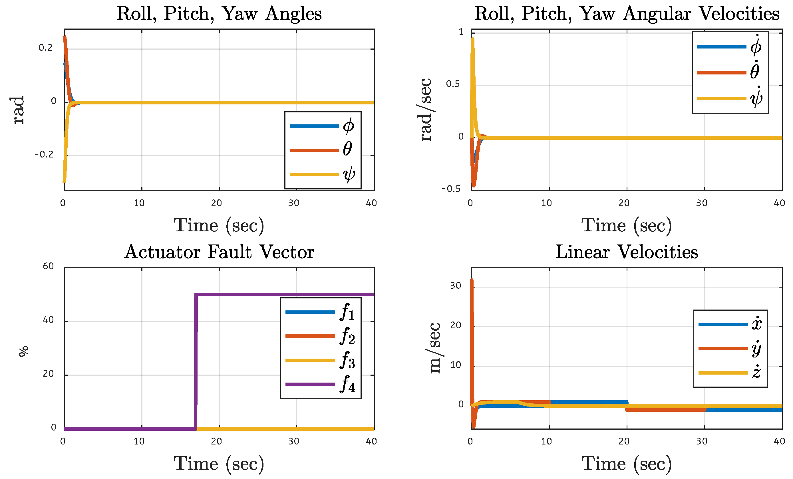
The graphs in this section show a comprehensive analysis of the quadcopter system orientation under varied fault conditions of motor 1 via both simulation-based and FPGA hardware-based results. The figure has six subfigures that display the system’s response at three levels of actuator faults (10%, 30%, and 50%). The simulation results for the case of a 10% fault in motor 1 are shown in Figure 42: they show the minor initial fluctuation of the roll, pitch, and yaw angle in simulation results, but these slowly stabilize and the actuator-fault vector confirms the presence of a fault and the linear velocities show an initial disturbance that quickly converges to a steady state. In Figure 43, the corresponding FPGA hardware-based results validate the practice applicability of the proposed control system with effective stabilization, and the transient response of the proposed control system. Additionally, other motors 2, 3, and 4, are also tested under 30% malfunction, the same effects were seen in these caused by the same 10% fault in motor 1. Figure 44 shows the simulation-based results, indicating that an increase in fault level to 30% leads to little oscillations of the angular and linear velocities but the system is still stable, which confirms the robustness of the fault-tolerant control strategy. In Figure 45, the FPGA implementation under the same fault level is also presented, showing that the experimental results match very well with the simulation results, implying that the control system can effectively keep higher fault levels without major error. The corresponding faults on a 30% degradation in motors 2, 3 and 4 produced results analogous to the effects caused by the same rating 30% fault applied to the motor 1. Figure 46 shows a severe 50% fault on motor 1 in the simulation environment, resulting in noticeable disturbances that the control system can compensate for while remaining on trajectory and experiencing minimal steady-state errors, but the FTC compensates the fault quickly. Figure 47 shows the FPGA hardware-based results which validate the simulation findings that the control algorithm can handle 50% fault and have consistent performance in all channels. Overall, these results show that the proposed control is very good at keeping the quadcopter stable and also tracking its desired trajectory even in the presence of significant motor faults. Given minimal differences between the simulation and hardware-based results, the control strategy appears to be highly reliable and robust in real-world control of precise orientation and velocity, despite actuator degradation. When testing a system response to a 50% fault for motors 2, 3 and 4; it was the same system response to a similar 50% fault in motor 1.

5.8. Quadcopter System Orientation Under Various Faults on the Other Motors of the Quadcopter

The above figures present the quadcopter’s orientation response to diverse fault scenarios, confirming the validity of the proposed control model during both simulation-based and FPGA-based analysis during the fault injections on motors 2, 3, and 4. Simulation-based results from Figure 48 are shown for 10 percent faults in motor 2 for roll, pitch, and yaw, their angular velocities in the initial deviation and, finally, stabilization by the proposed controller, owing to the fault-tolerant control system. In Figure 49 we provide the results from the FPGA hardware which matched the simulation, in turn validating the control method’s effectiveness in addressing 10% fault. Similarly, injecting a 10% fault on motors 1, 3, and 4 yielded identical results to those obtained with a fault on motor 2. Figure 50 shows simulation-based results corresponding to a 30% fault on motor 3; operations begin with the coordination of eliminating the fault but quickly stabilize and maintain consistent linear velocities. Figure 51 shows that the hardware-based results for this scenario match the emulated discrepancies between them. Likewise, injecting a 30% fault on motors 1, 2, and 4 yielded identical results to those obtained with 30% fault on motor 3. The simulation-based results for a 50% fault on motor 4 in Figure 52 show that the system has some initial big fluctuations but fluctuation decreases over time to zero. Figure 53 is shown with the FPGA hardware-based results verifying comparable stabilization performance in both environments, which further validates the fault-tolerant control mechanism being robust. Similarly, introducing a 50% fault on motors 1, 2, and 3 produced results that were identical to the results we got when a 50% fault was injected on motor 4. The effectiveness of the proposed fault-tolerant control strategy is validated by the fact that the actuator-fault vector clearly reflects the fault magnitude and that the system universally ensures translational and rotational stability across all fault scenarios.
Table 2 demonstrates that the steady-state error for rotational angular variables is represented by error ϕ , error θ , and error ψ , whereas the steady-state error for translational angular variables is represented by error x , error y , error z . This table demonstrates that the error rate for rotational motion is very low during both simulation-based analysis and FPGA implementation of the proposed quadcopter control system. It summarizes a comparative analysis of the control system’s performance under various fault conditions ranging from 10% to 50%, comparing simulation results with those obtained from FPGA hardware implementation. The effects observed are consistent across all test conditions, with error values coinciding to several decimal places. The proposed controller exhibits strong fault tolerance. During simulations, rotational errors remain negligible under all faulty conditions. In the FPGA implementation, minor errors occur but are still negligible. The results also show that translational errors are relatively low, although they increase from 0.0001 to 0.5829 when faults escalate from 10% to 50%. Notably, tracking performance in the x and y directions remains precise, while control in the z direction gradually deteriorates at the highest fault.
It is clear from the results that the z-direction of the quadcopter is more sensitive than the x and y directions because in the z-direction, the quadcopter continuously counteracts the gravitational force. Any small error in thrust directly affects altitude. To maintain exact altitude, altitude controllers often have higher gain, which increases the system’s sensitivity to disturbances and sensor noise. Another reason is the collective thrust of all motor controls the vertical motion of the quadcopter, while tilting (roll/pitch) is used to control horizontal motion, which disperses over several axes and makes x/y less immediately affected by rotor flaws than z.
The results further demonstrate that the proposed control system achieves strong rotational stability, with roll and pitch angles remaining within acceptable limits even under extreme disturbances. However, altitude stability is more sensitive, particularly in the z-direction, with an error of 0.583 at 50% motor fault severity. Notably, the coherence between simulation and FPGA-based experiments confirms the successful deployment of the proposed algorithms to FPGA hardware. These findings highlight that the fault-tolerant control architecture maintains reasonable performance even under severe conditions, sustaining up to 50% motor failure. The close alignment between simulated and hardware results instills confidence in the system’s field applicability and reliability.
Furthermore, the results of both the simulation-based analysis and hardware-based analysis are justified by conducting t-test analysis and an ANOVA test in MATLAB.
For all error components after 10% fault, the mean differences between simulation-based and FPGA-based results are minimal ( 10 6 10 5 ) as shown in the Table 3. Even when p-values show formal significance for some axes, the magnitudes are negligible—well below any practically meaningful threshold. After 30% fault, the mean differences remain on the order of ( 10 6 10 5 ), again reflecting tiny deviations. A few tests indicate statistical differences (e.g., Error θ with p 1.9 × 10 5 ) , but these arise purely from finite-precision sensitivity, not true performance drift. Despite higher fault injection, numerical errors stay very small—typically 10 5 10 4 magnitude or less. A few metrics (notably Error θ ) reach statistical significance because of their consistency, yet the absolute difference ( 2 × 10 5 10 4 ) is physically insignificant. We can conclude that the 10% fault condition demonstrates excellent agreement between simulation and hardware implementation; the two results are nearly identical numerically, at 30 % fault, both platforms yield almost indistinguishable steady-state errors; discrepancies are computationally trivial, and even under severe fault levels, FPGA execution reproduces simulation behavior with negligible numerical deviation, confirming the robustness of both the controller and estimator implementations.
Across all fault levels, the ANOVA results in the Table 4 show extremely small mean differences between simulation and FPGA implementations. The p-values, even when statistically small, correspond to negligible absolute errors, typically in the range of ( 10 6 10 5 or less, confirming practical equivalence between both domains. Even where p-values indicate statistical differences, the absolute magnitudes are extremely small 10 5 . Therefore, simulation and FPGA results are effectively identical under 10% fault injection. All metrics show nearly identical performance between FPGA and simulation. Even Error θ , with a small p-value, corresponds to a difference < 2 × 10 5 , confirming that variations are numerical, not behavioral. Even at 50% actuator fault, FPGA and simulation maintain excellent alignment. All deviations are at or below 10 4 , showing the fault-tolerant controller performs equivalently in hardware and software domains. Although formal ANOVA and Kruskal–Wallis tests occasionally indicate statistical significance, the effect sizes (mean differences) are orders of magnitude smaller than physical system tolerances or sensor noise. Hence, all results confirm that the FPGA-based implementation faithfully reproduces the simulation model outputs, with negligible numerical deviations across all fault levels.
This paper validates the proposed hybrid control system on a quadcopter, but the concept may be applied to other multirotor UAV types like octocopters or hexacopters because the nonlinear dynamics of the system, which have the same mathematical structure in multirotor topologies, are the source of the basic control laws of the proposed controller. The control allocation matrix, which associates individual rotor forces with the overall thrust and torque instructions, must be modified to adapt to new types of UAVs. To maintain convergence properties for different weight/thrust ratios, the suggested controller gains can be adjusted using the same Lyapunov-based stability conditions. Furthermore, the sliding-mode component offers robustness in outdoor settings, where aerodynamic disturbances are prevalent. As a result, the proposed method requires few structural changes and is still practical and efficient for a variety of UAV types.
Furthermore, the NL-DO can serve as a foundation for future fault detection and identification (FDI) systems, enabling early warnings of component degradation before catastrophic failures occur. By leveraging system modeling, residual generation, and fault detection/isolation mechanisms, the NL-DO can enhance FDI accuracy and robustness, ultimately improving system reliability.

6. Conclusions

In this paper, an advanced fault-tolerant control (FTC) strategy for quadcopter UAVs, based on integral backstepping control (IBSC) for translational motion and nonlinear observer-based sliding-mode control (NL-DO-SMC) for rotational motion control, is simulated and implemented on an FPGA. For the actuator faults, the proposed FTC framework consists of using a nonlinear observer to estimate the disturbance, unmodeled dynamics, and motor fault uncertainty, and facilitate smooth compensation using the sliding-mode controller to ensure stable flight. The results are validated extensively by both simulations and hardware-in-the-loop (HIL) experiments using FPGA hardware. The proposed control system was tested under different fault conditions, such as 10, 30, and 50 percent faults in a single motor. It is shown that at 50% motor fault condition, the achieved FTC still provides full control of the quadcopter on all flight channels: roll, pitch, yaw, and translational axes, with stable trajectory tracking and attitude control. HIL experiments further confirmed the robustness of the control scheme and demonstrated that it is practical for real-world applications. Future research directions involve expanding the scope of the proposed FTC framework to other cases when there are multiple simultaneous motor faults and sensor faults. The integration of the nonlinear observer as a fault detection and identification (FDI) mechanism in the control system will provide enhanced fault isolation and enhance the overall reliability of the UAV.

Author Contributions

All authors (M.A., A.Z., J.H.A., A.S.A., M.Z.B., M.R. and G.H.) have contributed as follows: methodology, formal analysis, simulation, and FPGA-based experimental analysis and validation, M.A., M.Z.B., and M.R.; literature review and writing—original draft preparation, J.H.A.; and writing—review and editing, A.Z., A.S.A., and G.H. All authors have read and approved the final version of the manuscript.

Funding

This work was supported in part by the Deanship of Scientific Research (DSR) at King Faisal University under Grant No. KFU253684.

Data Availability Statement

Additionally, simulation results, hardware implementation videos, and experimental data are available at: https://drive.google.com/drive/folders/1RRCOv-_Eu2NpUv3pqYPpg6gACSdfjx5e?usp=drive_link (accessed on 29 August 2025). This repository is recommended for all, as it contains detailed results of the simulation and hardware setups, and validation. The drive link is accessible to everyone.

Acknowledgments

The authors would like to express their sincere gratitude to Heriot-Watt University for their support of this research work.

Conflicts of Interest

The authors declare no conflicts of interest.

References

  1. Valianti, P.; Kolios, P.; Ellinas, G. Energy-aware tracking and jamming rogue UAVs using a swarm of pursuer UAV agents. IEEE Syst. J. 2022, 17, 1524–1535. [Google Scholar] [CrossRef]
  2. Kwon, D.; Son, S.; Kim, M.H.; Lee, J.Y.; Das, A.K.; Park, Y. A Secure Self-Certified Broadcast Authentication Protocol for Intelligent Transportation Systems in UAV-Assisted Mobile Edge Computing Environments. IEEE Trans. Intell. Transp. Syst. 2024, 25, 19004–19017. [Google Scholar] [CrossRef]
  3. Mukhamediev, R.I.; Yakunin, K.; Aubakirov, M.; Assanov, I.; Kuchin, Y.; Symagulov, A.; Levashenko, V.; Zaitseva, E.; Sokolov, D.; Amirgaliyev, Y. Coverage Path Planning Optimization of Heterogeneous UAVs Group for Precision Agriculture. IEEE Access 2023, 11, 5789–5803. [Google Scholar] [CrossRef]
  4. Hu, S.; Yuan, X.; Ni, W.; Wang, X.; Jamalipour, A. Visual-Based Moving Target Tracking with Solar-Powered Fixed-Wing UAV: A New Learning-Based Approach. IEEE Trans. Intell. Transp. Syst. 2024, 25, 9115–9129. [Google Scholar] [CrossRef]
  5. Alhafnawi, M.; Salameh, H.A.B.; Masadeh, A.E.; Al-Obiedollah, H.; Ayyash, M.; El-Khazali, R.; Elgala, H. A Survey of Indoor and Outdoor UAV-Based Target Tracking Systems: Current Status, Challenges, Technologies, and Future Directions. IEEE Access 2023, 11, 68324–68339. [Google Scholar] [CrossRef]
  6. Song, L.; Wan, N.; Gahlawat, A.; Tao, C.; Hovakimyan, N.; Theodorou, E.A. Generalization of Safe Optimal Control Actions on Networked Multiagent Systems. IEEE Trans. Control Netw. Syst. 2022, 10, 491–502. [Google Scholar] [CrossRef]
  7. Kusmirek, S.; Socha, V.; Malich, T.; Socha, L.; Hylmar, K.; Hanakova, L. Dynamic Flight Tracking: Designing System for Multirotor UAVs with Pixhawk Autopilot Data Verification. IEEE Access 2024, 12, 109806–109821. [Google Scholar] [CrossRef]
  8. Zhou, Z.; Liu, Y. A Smart Landing Platform with Data-Driven Analytic Procedures for UAV Preflight Safety Diagnosis. IEEE Access 2021, 9, 154876–154891. [Google Scholar] [CrossRef]
  9. Ventura, J.O.; Morales, D.B.; Oliver, J.P.O.; Quesada, E.S.E. Dynamic Sliding Mode Control with PID Surface for Trajectory Tracking of a Multirotor Aircraft. IEEE Access 2023, 11, 99878–99888. [Google Scholar] [CrossRef]
  10. Liu, B.; Wang, Y.; Mofid, O.; Mobayen, S.; Khooban, M.H. Barrier Function-Based Backstepping Fractional-Order Sliding Mode Control for Quad-Rotor Unmanned Aerial Vehicle under External Disturbances. IEEE Trans. Aerosp. Electron. Syst. 2023, 60, 716–728. [Google Scholar] [CrossRef]
  11. Xu, L.X.; Wang, Y.L.; Wang, X.; Peng, C. Distributed Active Disturbance Rejection Formation Tracking Control for Quadrotor UAVs. IEEE Trans. Cybern. 2023, 54, 4678–4689. [Google Scholar] [CrossRef]
  12. Gai, W.; Zhou, Y.; Zhong, M.; Sheng, C.; Zhang, J. Simple Adaptive Control with an Adaptive Anti-Windup Compensator for the Unmanned Aerial Vehicle Attitude Control. IEEE Access 2020, 8, 52323–52332. [Google Scholar] [CrossRef]
  13. Chen, B.-S.; Hung, T.-W. Integrating Local Motion Planning and Robust Decentralized Fault-Tolerant Tracking Control for Search and Rescue Task of Hybrid UAVs and Biped Robots Team System. IEEE Access 2023, 11, 45888–45909. [Google Scholar] [CrossRef]
  14. Nguyen, D.-T.; Saussie, D.; Saydy, L. Design and experimental validation of robust self-scheduled fault-tolerant control laws for a multicopter UAV. IEEE/ASME Trans. Mechatronics 2020, 26, 2548–2557. [Google Scholar] [CrossRef]
  15. Avram, R.C.; Zhang, X.; Muse, J. Nonlinear adaptive fault-tolerant quadrotor altitude and attitude tracking with multiple actuator faults. IEEE Trans. Control Syst. Technol. 2017, 26, 701–707. [Google Scholar] [CrossRef]
  16. Yu, Z.; Zhang, Y.; Jiang, B. PID-type fault-tolerant prescribed performance control of fixed-wing UAV. J. Syst. Eng. Electron. 2021, 32, 1053–1061. [Google Scholar]
  17. Mofid, O.; Mobayen, S.; Wong, W.-K. Adaptive terminal sliding mode control for attitude and position tracking control of quadrotor UAVs in the existence of external disturbance. IEEE Access 2020, 9, 3428–3440. [Google Scholar] [CrossRef]
  18. Cohen, M.R.; Abdulrahim, K.; Forbes, J.R. Finite-horizon LQR control of quadrotors on SE2(3). IEEE Robot. Autom. Lett. 2020, 5, 5748–5755. [Google Scholar] [CrossRef]
  19. Aliyari, M.; Wong, W.-K.; Bouteraa, Y.; Najafinia, S.; Fekih, A.; Mobayen, S. Design and implementation of a constrained model predictive control approach for unmanned aerial vehicles. IEEE Access 2022, 10, 91750–91762. [Google Scholar] [CrossRef]
  20. Gu, J.; Sun, R.; Chen, J. Improved back-stepping control for nonlinear small UAV systems with transient prescribed performance design. IEEE Access 2021, 9, 128786–128798. [Google Scholar] [CrossRef]
  21. Du, Y.; Huang, P.; Cheng, Y.; Fan, Y.; Yuan, Y. Fault tolerant control of a quadrotor unmanned aerial vehicle based on active disturbance rejection control and two-stage Kalman filter. IEEE Access 2023, 11, 67556–67566. [Google Scholar] [CrossRef]
  22. Zou, Y.; Xia, K. Robust fault-tolerant control for underactuated takeoff and landing UAVs. IEEE Trans. Aerosp. Electron. Syst. 2020, 56, 3545–3555. [Google Scholar] [CrossRef]
  23. Ortiz-Torres, G.; Castillo, P.; Sorcia-Vázquez, F.D.; Rumbo-Morales, J.Y.; Brizuela-Mendoza, J.A.; De La Cruz-Soto, J.; Martínez-García, M. Fault estimation and fault tolerant control strategies applied to VTOL aerial vehicles with soft and aggressive actuator faults. IEEE Access 2020, 8, 10649–10661. [Google Scholar] [CrossRef]
  24. Lee, D.; Park, H.J.; Lee, D.; Lee, S.; Choi, J.-H. A Novel Kalman Filter-Based Prognostics Framework for Performance Degradation of Quadcopter Motors. IEEE Trans. Instrum. Meas. 2023, 73, 3501312. [Google Scholar] [CrossRef]
  25. Freire, V.; Xu, X. Flatness-Based Quadcopter Trajectory Planning and Tracking with Continuous-Time Safety Guarantees. IEEE Trans. Control Syst. Technol. 2023, 31, 2319–2334. [Google Scholar] [CrossRef]
  26. Miloš, M.; Mirosavljević, P. Analysis of the Performance and Kinematics of the Movement of UAV. FME Trans. 2023, 51, 627–636. [Google Scholar] [CrossRef]
  27. Ullah, S. Design a Nonlinear Controller for a Quadcopter. Ph.D. Thesis, COMSATS Institute of Information Technology, Chak Shahzad, Pakistan, 2016. [Google Scholar]
  28. Su, Y.; Yu, P.; Gerber, M.J.; Ruan, L.; Tsao, T.C. Fault-Tolerant Control of an Overactuated UAV Platform Built on Quadcopters and Passive Hinges. IEEE/ASME Trans. Mechatronics 2023, 29, 602–613. [Google Scholar] [CrossRef]
  29. Bao, C.; Guo, Y.; Luo, L.; Su, G. Design of a Fixed-Wing UAV Controller Based on Adaptive Backstepping Sliding Mode Control Method. IEEE Access 2021, 9, 157825–157841. [Google Scholar] [CrossRef]
  30. Gaufan, K.S.B.; El-Ferik, S.; Alyazidi, N.M. Fractional Model-Based Formation Control of Quad-Rotor UAVs Using Sliding Mode Backstepping. IEEE Access 2024, 12, 166460–166473. [Google Scholar] [CrossRef]
  31. Esmail, M.S.; Merzban, M.H.; Khalaf, A.A.; Hamed, H.F.; Hussein, A.I. Attitude and Altitude Tracking Controller for Quadcopter Dynamical Systems. IEEE Access 2022, 10, 53344–53358. [Google Scholar] [CrossRef]
  32. Gavgani, A.K.; Talaeizadeh, A.; Heidarzadeh, S.; Alasty, A.; Pishkenari, H.N. Dynamic Modeling and Sliding Mode Control of an Over-Actuated Quadrotor with Variable Hedral Angle of Propeller Axes. In Proceedings of the 2024 2nd International Conference on Unmanned Vehicle Systems-Oman (UVS), Muscat, Oman, 12–14 February 2024; IEEE: Piscataway, NJ, USA, 2024; pp. 1–6. [Google Scholar]
  33. Liu, Y.; Wang, H.; Liu, B.; Chen, L.; Wang, Y.; Chen, H. Learning-Based Compound Docking Control for UAV Aerial Recovery: Methodology and Implementation. IEEE/ASME Trans. Mechatronics 2022, 28, 1706–1717. [Google Scholar] [CrossRef]
  34. Huang, J.; Ma, X.; Wang, B.; Zhang, Y.; Xin, G.; Zhang, Y. Trajectory Tracking Control of a Quadrotor UAV by Cascaded Inner-Outer-Loop Backstepping Sliding Mode Control. In Proceedings of the 2022 34th Chinese Control and Decision Conference (CCDC), Hefei, China, 15–17 August 2022; IEEE: Piscataway, NJ, USA, 2022; pp. 4725–4730. [Google Scholar]
  35. Chen, X. Terminal Sliding Mode Controller Design Based on Barrier for UAVs With Mismatched Disturbances. IEEE Access 2024, 12, 137942–137951. [Google Scholar] [CrossRef]
  36. Gai, W.; Song, H.; Zhang, G.; Jing, G. An Automatic Collision Avoidance with Disturbance Interval Observer for Unmanned Aerial Vehicle. In Proceedings of the 2023 2nd Conference on Fully Actuated System Theory and Applications (CFASTA), Qingdao, China, 14–16 July 2023; IEEE: Piscataway, NJ, USA, 2023; pp. 1085–1090. [Google Scholar]
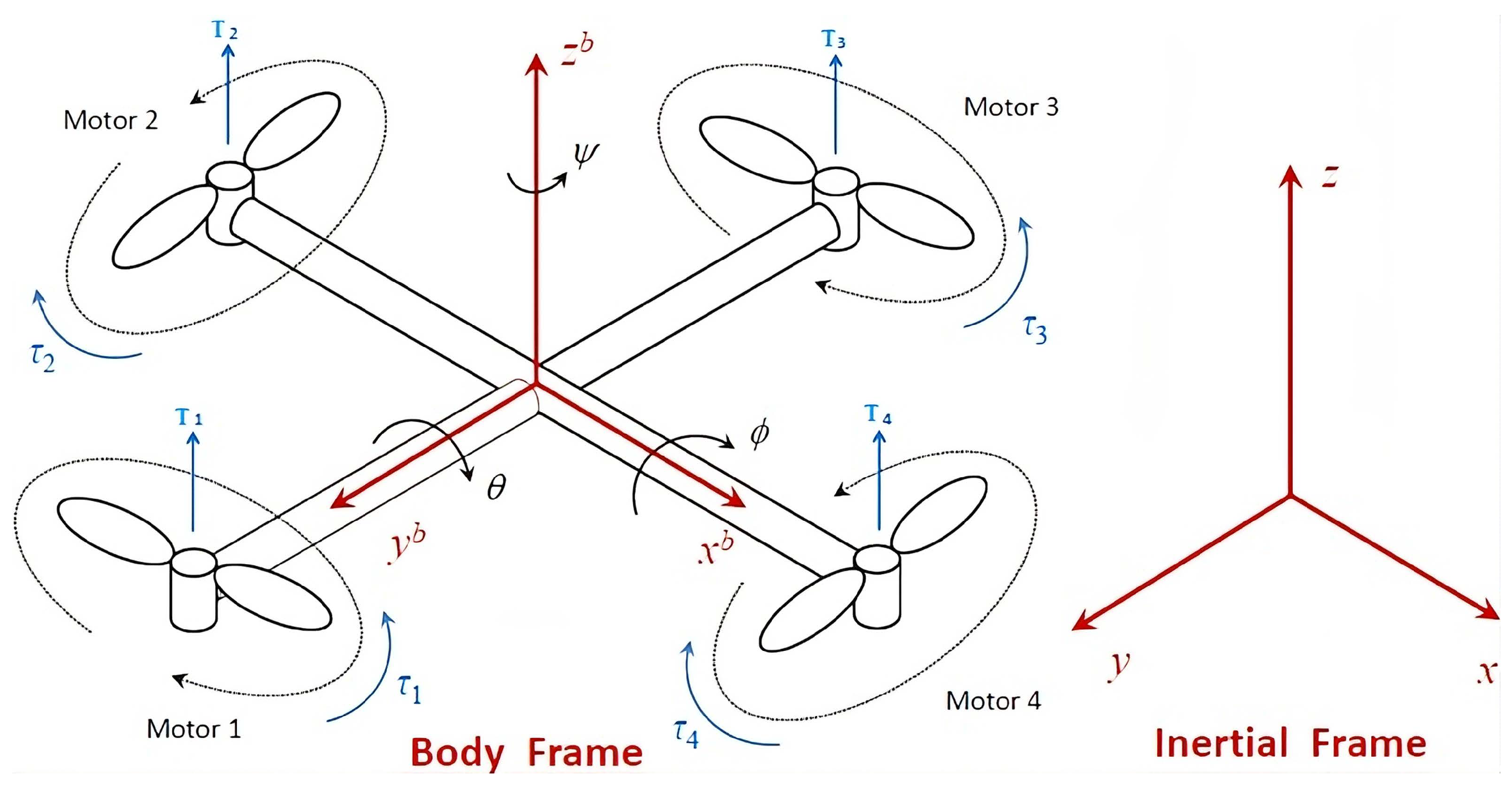
Figure 1. A rotational diagram of the quadcopter.
Fractalfract 09 00682 g001
Figure 2. Flowchart of this work.
Fractalfract 09 00682 g002
Figure 3. Block diagram of the proposed work.
Fractalfract 09 00682 g003
Figure 4. FPGA-based experimental setup.
Fractalfract 09 00682 g004
Figure 5. Desired trajectory.
Fractalfract 09 00682 g005
Figure 6. Trajectory with 10% fault on motor 1 (simulation-based).
Fractalfract 09 00682 g006
Figure 7. Trajectory with 10% fault on motor 1 (FPGA-based).
Fractalfract 09 00682 g007
Figure 8. Trajectory with 30% fault on motor 1 (simulation-based).
Fractalfract 09 00682 g008
Figure 9. Trajectory with 30% fault on motor 1 (FPGA-based).
Fractalfract 09 00682 g009
Figure 10. Trajectory with 50% fault on motor 1 (simulation-based).
Fractalfract 09 00682 g010
Figure 11. Trajectory with 50% fault on motor 1 (FPGA-based).
Fractalfract 09 00682 g011
Figure 12. Trajectory with 10% fault on motor 2 (simulation-based).
Fractalfract 09 00682 g012
Figure 13. Trajectory with 10% fault on motor 2 (FPGA-based).
Fractalfract 09 00682 g013
Figure 14. Trajectory with 30% fault on motor 2 (simulation-based).
Fractalfract 09 00682 g014
Figure 15. Trajectory with 30% fault on motor 2 (FPGA-based).
Fractalfract 09 00682 g015
Figure 16. Trajectory with 50% fault on motor 2 (simulation-based).
Fractalfract 09 00682 g016
Figure 17. Trajectory with 50% fault on motor 2 (FPGA-based).
Fractalfract 09 00682 g017
Figure 18. Trajectory with 10% fault on motor 3 (simulation-based).
Fractalfract 09 00682 g018
Figure 19. Trajectory with 10% fault on motor 3 (FPGA-based).
Fractalfract 09 00682 g019
Figure 20. Trajectory with 30% fault on motor 3 (simulation-based).
Fractalfract 09 00682 g020
Figure 21. Trajectory with 30% fault on motor 3 (FPGA-based).
Fractalfract 09 00682 g021
Figure 22. Trajectory with 50% fault on motor 3 (simulation-based).
Fractalfract 09 00682 g022
Figure 23. Trajectory with 50% fault on motor 3 (FPGA-based).
Fractalfract 09 00682 g023
Figure 24. Trajectory with 10% fault on motor 4 (simulation-based).
Fractalfract 09 00682 g024
Figure 25. Trajectory with 10% fault on motor 4 (FPGA-based).
Fractalfract 09 00682 g025
Figure 26. Trajectory with 30% fault on motor 4 (simulation-based).
Fractalfract 09 00682 g026
Figure 27. Trajectory with 30% fault on motor 4 (FPGA-based).
Fractalfract 09 00682 g027
Figure 28. Trajectory with 50% fault on motor 4 (simulation-based).
Fractalfract 09 00682 g028
Figure 29. Trajectory with 50% fault on motor 4 (FPGA-based).
Fractalfract 09 00682 g029
Figure 30. Three-dimensional track with 10% fault on motor 1 (simulation-based).
Fractalfract 09 00682 g030
Figure 31. Three-dimensional track with 10% fault on motor 1 (FPGA-based).
Fractalfract 09 00682 g031
Figure 32. Three-dimensional track with 30% fault on motor 1 (simulation-based).
Fractalfract 09 00682 g032
Figure 33. Three-dimensional track with 30% fault on motor 1 (FPGA-based).
Fractalfract 09 00682 g033
Figure 34. Three-dimensional track with 50% fault on motor 1 (simulation-based).
Fractalfract 09 00682 g034
Figure 35. Three-dimensional track with 50% fault on motor 1 (FPGA-based).
Fractalfract 09 00682 g035
Figure 36. Three-dimensional track with 10% fault on motor 2 (simulation-based).
Fractalfract 09 00682 g036
Figure 37. Three-dimensional track with 10% fault on motor 2 (FPGA-based).
Fractalfract 09 00682 g037
Figure 38. Three-dimensional track with 30% fault on motor 3 (simulation-based).
Fractalfract 09 00682 g038
Figure 39. Three-dimensional track with 30% fault on motor 3 (FPGA-based).
Fractalfract 09 00682 g039
Figure 40. Three-dimensional track with 50% fault on motor 4 (simulation-based).
Fractalfract 09 00682 g040
Figure 41. Three-dimensional track with 50% fault on motor 4 (FPGA-based).
Fractalfract 09 00682 g041
Figure 42. System orientation under 10% fault on motor 1 (simulation-based).
Fractalfract 09 00682 g042
Figure 43. System orientation under 10% fault on motor 1 (FPGA-based).
Fractalfract 09 00682 g043
Figure 44. System orientation under 30% fault on motor 1 (simulation-based).
Fractalfract 09 00682 g044
Figure 45. System orientation under 30% fault on motor 1 (FPGA-based).
Fractalfract 09 00682 g045
Figure 46. System orientation under 50% fault on motor 1 (simulation-based).
Fractalfract 09 00682 g046
Figure 47. System orientation under 50% fault on motor 1 (FPGA-based).
Fractalfract 09 00682 g047
Figure 48. System orientation under 10% fault on motor 2 (simulation-based).
Fractalfract 09 00682 g048
Figure 49. System orientation under 10% fault on motor 2 (FPGA-based).
Fractalfract 09 00682 g049
Figure 50. System orientation under 30% fault on motor 3 (simulation-based).
Fractalfract 09 00682 g050
Figure 51. System orientation under 30% fault on motor 3 (FPGA-based).
Fractalfract 09 00682 g051
Figure 52. System orientation under 50% fault on motor 4 (simulation-based).
Fractalfract 09 00682 g052
Figure 53. System orientation under 50% fault on motor 4 (FPGA-based).
Fractalfract 09 00682 g053
Table 1. Factors and their values used in modeling.
Translational GainRotational GainInitial PointTuning Factor
k 1 = 12.4 ζ 7 = 0.698 x 0 = 1 η 4 = 2
k 2 = 4.3 ζ 8 = 7.005 y 0 = 1 η 5 = 3
k 3 = 9.6 ζ 9 = 0.365 z 0 = 0 η 6 = 4
k 4 = 5.7 ζ 10 = 11.023 φ 0 = 0.15
k 5 = 9.2 ζ 11 = 0.025 θ 0 = 0.25
k 6 = 5.1 ζ 12 = 12.025 ψ 0 = 0.3
Table 2. Statistical analysis.
Numerical Results
Simulation-Based Results FPGA-Based Results
After Injecting 10% Fault Motor 1Motor 2Motor 3Motor 4 Motor 1Motor 2Motor 3Motor 4
Error x 1.02 × 10 4 1.02 × 10 4 1.02 × 10 4 1.02 × 10 4 1.02 × 10 4 1.02 × 10 4 1.02 × 10 4 1.02 × 10 4
Error y 9.15 × 10 5 9.15 × 10 5 9.15 × 10 5 9.15 × 10 5 9.34 × 10 5 9.34 × 10 5 9.34 × 10 5 9.34 × 10 5
Error z 0.103410.103410.103410.10341 0.103400.103400.103400.10340
Error ϕ 0000 1.57 × 10 5 1.57 × 10 5 1.57 × 10 5 1.57 × 10 5
Error θ 0000 1.69 × 10 5 1.69 × 10 5 1.69 × 10 5 1.69 × 10 5
Error ψ 0000 1.90 × 10 5 1.90 × 10 5 1.90 × 10 5 1.90 × 10 5
After Injecting 30% Fault Motor 1Motor 2Motor 3Motor 4 Motor 1Motor 2Motor 3Motor 4
Error x 1.02 × 10 4 1.02 × 10 4 1.02 × 10 4 1.02 × 10 4 1.02 × 10 4 1.02 × 10 4 1.02 × 10 4 1.02 × 10 4
Error y 9.20 × 10 5 9.20 × 10 5 9.20 × 10 5 9.20 × 10 5 9.34 × 10 5 9.34 × 10 5 9.34 × 10 5 9.34 × 10 5
Error z 0.330220.330220.330220.33022 0.33020.33020.33020.3302
Error ϕ 0000 1.58 × 10 5 1.58 × 10 5 1.58 × 10 5 1.58 × 10 5
Error θ 0000 2.06 × 10 5 1.90 × 10 5 1.90 × 10 5 1.90 × 10 5
Error ψ 0000 1.90 × 10 5 1.90 × 10 5 1.90 × 10 5 1.90 × 10 5
After Injecting 50% Fault Motor 1Motor 2Motor 3Motor 4 Motor 1Motor 2Motor 3Motor 4
Error x 1.26 × 10 11 1.26 × 10 11 1.26 × 10 11 1.26 × 10 11 5.8 × 10 11 5.9 × 10 11 5.8 × 10 11 5.9 × 10 11
Error y 5.34 × 10 18 5.34 × 10 18 5.34 × 10 18 5.34 × 10 18 2.66 × 10 10 2.72 × 10 10 2.60 × 10 10 2.71 × 10 10
Error z 0.582930.582930.582930.58293 0.58390.58390.58390.5839
Error ϕ 0000 1.59 × 10 5 1.59 × 10 5 1.59 × 10 5 1.59 × 10 5
Error θ 0000 2.73 × 10 5 1.90 × 10 5 1.90 × 10 5 1.90 × 10 5
Error ψ 0000 1.90 × 10 5 1.90 × 10 5 1.90 × 10 5 1.90 × 10 5
Table 3. T-test results.
Fault_LvlMetricMean_SimMean_FPGAMean_Diffp_ttestp_wilcoxonN_effCI_low
10% Error x 0.0001020.0001020114
Error y 0.00009150.0000934−1.9 × 10 6 004−1.9 × 10 6
Error z 0.103410.10341 × 10 5 0041 × 10 5
Error ϕ 00.0000157−0.0000157004−0.0000157
Error θ 00.0000169−0.0000169004−0.0000169
Error ψ 00.000019−0.000019004−0.000019
30% Error x 0.0001020.0001020114
Error y 0.0000920.0000934−1.4 × 10 6 004−1.4 × 10 6
Error z 0.330220.33022 × 10 5 0042 × 10 5
Error ϕ 00.0000158−0.0000158004−0.0000158
Error θ 00.0000194−0.00001941.93 × 10 5 0.1254−2.0673 × 10 5
Error ψ 00.000019−0.000019004−0.000019
50% Error x 1.26 × 10 11 5.85 × 10 11 −4.59 × 10 11 5.49 × 10 7 0.1254−4.68187 × 10 11
Error y 5.34 × 10 18 2.6725 × 10 10 −2.6725 × 10 10 2.4 × 10 6 0.1254−2.76002 × 10 10
Error z 0.582930.5839−0.00097004−0.00097
Error ϕ 00.0000159−0.0000159004−0.0000159
Error θ 00.000021075−0.0000210750.0020340.1254−2.76786 × 10 5
Error ψ 00.000019−0.000019004−0.000019
Table 4. ANOVA test results.
Fault_LvlMetricMean_SimMean_FPGAMean_Diffp_anovap_kruskalN_total
10% Error x 0.0001020.0001020118
Error y 0.00009150.0000934−1.9 × 10 6 008
Error z 0.103410.10341 × 10 5 008
Error ϕ 00.0000157−1.57 × 10 5 008
Error θ 00.0000169−1.69 × 10 5 008
Error ψ 00.000019−0.000019008
30% Error x 0.0001020.0001020118
Error y 0.0000920.0000934−1.4 × 10 6 008
Error z 0.330220.33022 × 10 5 008
Error ϕ 00.0000158−1.58 × 10 5 008
Error θ 00.0000194−1.94 × 10 5 5.15168 × 10 9 0.0114120368
Error ψ 00.000019−0.000019008
50% Error x 1.26 × 10 11 5.85 × 10 11 −4.59 × 10 11 4.17459 × 10 12 0.0126156678
Error y 5.34 × 10 18 2.6725 × 10 10 −2.6725 × 10 10 7.99963 × 10 11 0.0138744068
Error z 0.582930.5839−0.00097008
Error ϕ 00.0000159−0.0000159008
Error θ 02.1075 × 10 5 −0.0000210755.30041 × 10 5 0.0114120368
Error ψ 00.000019−0.000019008
Disclaimer/Publisher’s Note: The statements, opinions and data contained in all publications are solely those of the individual author(s) and contributor(s) and not of MDPI and/or the editor(s). MDPI and/or the editor(s) disclaim responsibility for any injury to people or property resulting from any ideas, methods, instructions or products referred to in the content.