Article

Application of Tilt Integral Derivative for Efficient Speed Control and Operation of BLDC Motor Drive for Electric Vehicles

1
Faculty of Engineering, Sohag University, Sohag 82524, Egypt
2
Faculty of Technology and Education, Sohag University, Sohag 82524, Egypt
3
Faculty of Engineering, Assiut University, Assiut 71518, Egypt
*
Author to whom correspondence should be addressed.
Fractal Fract. 2024, 8(1), 61; https://doi.org/10.3390/fractalfract8010061
Submission received: 7 December 2023 / Revised: 3 January 2024 / Accepted: 11 January 2024 / Published: 16 January 2024

Abstract

:
This study presents the tilt integral derivative (TID) controller technique for controlling the speed of BLDC motors in order to improve the real-time control of brushless direct current motors in electric vehicles. The TID controller is applied to the considered model to enhance its performance, e.g., torque and speed. This control system manages the torque output, speed, and position of the motor to ensure precise and efficient operation in EV applications. Brushless direct current motors are becoming more and more popular due to their excellent torque, power factor, efficiency, and controllability. The differences between PID, TID, and PI controllers are compared. The outcomes demonstrated that the TID control enhanced the torque and current stability in addition to the BLDC system’s capacity to regulate speed. TID controllers provide better input power for BLDC (brushless DC) drives than PI and PID controllers do. Better transient responsiveness and robustness to disturbances are features of TID controller design, which can lead to more effective use of input power. TID controllers are an advantageous choice for BLDC drive applications because of their increased performance, which can result in increased system responsiveness and overall efficiency. In an experimental lab, a BLDC motor drive prototype is implemented in this study. To fully enhance the power electronic subsystem and the brushless DC motor’s real-time performance, a test bench was also built.

1. Introduction

Brushless DC (BLDC) motors have become an integral part of the aviation industry, particularly in the development of electric vehicles. These motors offer numerous advantages over traditional motors, making them highly suitable for various applications in electric vehicle systems. One of the key applications of BLDC motors is in electric propulsion, where they serve as the main propulsion system. With their high torque and efficiency, BLDC motors enable electric vehicles to achieve higher speeds and longer flight durations. Additionally, BLDC motors are used as actuators in critical systems such as flight control surfaces, landing gear, and cargo doors, providing precise and reliable movement. They are also utilized in environmental control systems to regulate cabin temperature and airflow, ensuring passenger comfort. Moreover, BLDC motors play a vital role in power generation, fuel pumps, and cooling systems, contributing to the overall energy management and performance of the vehicle. The utilization of BLDC motors in vehicle systems not only reduces reliance on traditional mechanical and hydraulic systems but also enhances efficiency and performance [1,2]. Because of their straightforward design, high torque output, extended life span, and high efficiency, brushless DC motors (BLDCMs) have found extensive use in industrial automation, home appliances, automobile, electronics, and aerospace industries. However, obtaining correct information about rotor location and speed is crucial to controlling these [3]. After decades of study by academics domestically and internationally, certain advances have been made in the investigation of brushless DC motor non-position control technology. Using a counter-electromotive force, which is now the most developed in use, can detect the signal of the counter-electromotive force derived from the voltage at the motor terminals and acquire commutation information with a 300 ms time delay, yet detecting it is challenging. The presence of the phase-shift issue is solved using a filter circuit. At high speed, it is more significant and even has the potential to cause commutation failure at low speeds due to the counter electromotive force [4].
Vehicles have historically used various electric motor types as their propulsion technology. They include permanent magnet brushless, brushed DC motors, induction motors (IMs), switching reluctance motors (SRMs), and BLDC motors. The motor types and drives used in EVs have thus been reviewed. Comparative analysis of the efficiency, cost, maximum speed, and reliability of switching resistance motors, induction motors, constant magnet motors, and DC motors to determine the best electric motor drivers for applications involving EVs and research on axial flux permanent magnet brushless DC motors is being undertaken. Our studies indicate that the preferred option for electric vehicle motor drives is motor drivers for brushless DC motors with axial flux [5].
Brushless DC motors have an expanded speed range, greater dependability, and efficiency. Biomedical and robotic applications [6] necessitate a strong torque-to-weight ratio and accurate position control for precision, since BLDC motors are used a great deal in various industrial and consumer durables due to their distinct properties. In contrast to its AC and DC counterparts, the BLDC motor may thus be considered a suitable solution [7]. Based on feedback from the rotor position, electronic commutation is used for BLDC motors instead of mechanical commutation. This feedback can be sensor-based or sensor-free. It is position sensors are vulnerable to changes in physical parameters, including temperature, pressure, and humidity. Hence, it has become more popular to use sensor-less rotor position detection [8,9]. The key sensor-less methods are the artificial intelligence-based strategy, the back EMF approach, the flux linkage approach, the inductance approach, and the back-EMF technique.
Due to its inherent advantages of having a straightforward structure and reliable operation, control using the proportional integral and derivative (PID) method is frequently employed within the industry [10]. Over 95% of industrial closed-loop controllers are PID- or PI-based. Even in the current environment [11], however, due to the nonlinear nature of the latter, this controller is not thought to be appropriate for BLDC motors. Since 1918, electric vehicles (EVs) have been a possibility [12,13,14,15,16].
Since then, the employment of electric vehicles for road transportation has significantly decreased due to rapid internal combustion engine (ICE) development and viability. However, current issues with air pollution, a shortage of and significant price increases for petroleum supplies, as well as energy independence, have prompted a reorganization of using electric vehicles as a substitute for other modes of transportation. Electric vehicle applications in the 20th century frequently utilized both drives with variable speeds for both DC and AC [17,18,19,20].
There are several applications of brushless DC motors in electric vehicles [21,22,23,24,25,26,27]. Some of them include the following.
  • Electric power steering: BLDC motors are commonly used in electric power steering systems in electric vehicles to provide precise and efficient steering control.
  • Electric braking systems: BLDC motors are used in regenerative braking systems in electric vehicles to convert kinetic energy into electrical energy and recharge the vehicle’s battery.
  • Electric cooling systems: BLDC motors are used in electric vehicle cooling systems to regulate the temperature of the vehicle’s battery, motor, and other components.
  • Electric HVAC systems: BLDC motors are used in electric vehicle heating, ventilation, and air-conditioning systems to provide efficient and reliable climate control.
  • Electric propulsion systems: BLDC motors are used in electric propulsion systems to drive the vehicle’s wheels or provide propulsion for other components such as pumps or fans.
  • Electric actuators: BLDC motors are used in electric vehicle actuators for applications such as adjusting mirrors, seats, and other components.
Overall, BLDC motors play a crucial role in various applications within electric vehicles, providing efficient and precise control for a wide range of systems and components. However, brushless DC motors play a crucial role in enabling the electrification of EV systems, reducing reliance on traditional mechanical and hydraulic systems and improving overall efficiency and performance [28,29,30]. Hence, the motor is maintenance-free, tough, and strong since there are no brushes, making it perfect for industrial applications. BLDC motors have a low moment of inertia, high efficiency, and high volumetric torque thanks to the rotor’s fixed magnetic field and the permanent magnets installed [30].
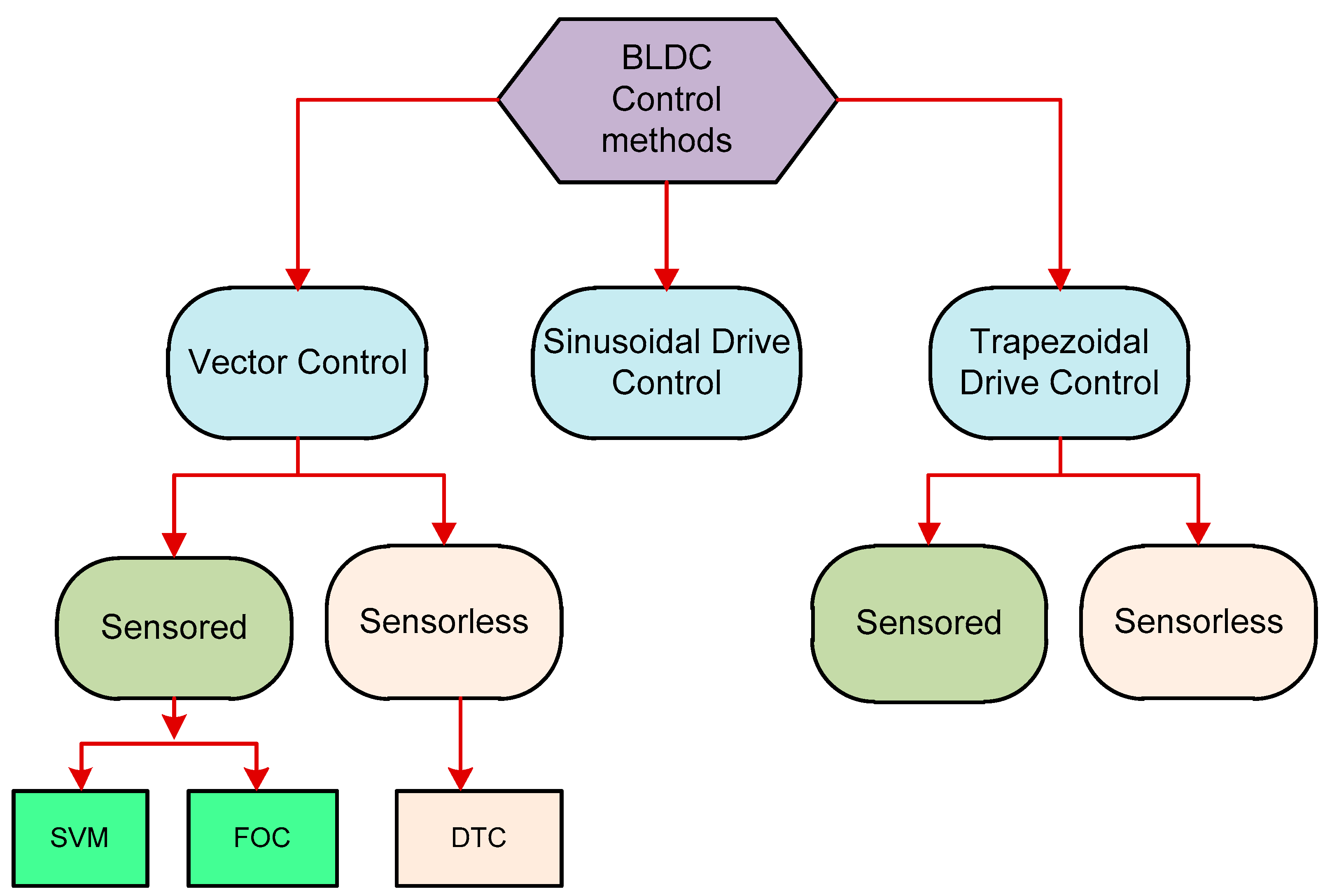
The stator and rotor are the two components that make up a BLDC motor. Figure 1 depicts the classification of types of BLDC motors. The motor can be built in a variety of ways, including with two rotors, one inside the other. The outer rotor-designed BLDC motor is covered in [31]. The stator windings are kept stationary inside, while on the outside surface, a permanent magnet is inserted in the rotor. The motor’s output torque and the outer rotor BLDC improve power density. Drones, variable-drive industries, water pumps, electric cars, and home electronics are the principal applications for the BLDC motor’s outer rotor. The distance in air gap between the stator and the rotor is reduced while designing an outer rotor BLDC motor [32,33,34,35], and current-dependent torque capacity will increase. To improve the stability of the rotor, structural components are introduced [32]. With these, motor abilities in dynamic situations are improved.
BLDC motors are anticipated to perform more quietly, have a greater torque-to-weight ratio, and be more efficient than previous motors [5]. These devices set up the motor to run at unity power factor by having a fixed magnetic flux between the rotor and stator. An electrically commutated motor drive provides power to a BLDC motor.
A BLDC motor is an electronically commutated device comparable to an AC synchronous machine. It produces trapezoidal back EMF, and depending on where the hall sensors are located in the motor’s stator, the two stator windings are stimulated during each condition. The rotor magnet position is detected through sensors. Any time the rotor poles come into proximity to the hall sensors, high or low signals are generated. The precise commutation sequence is determined using the combination of hall sensors. The activation of the windings in the stator of a BLDC motor is crucial for its operation, as it determines the rotation of the motor. To rotate, the BLDC motor stator’s windings must be turned on one after the other [35,36,37,38].
When comparing BLDC motors with other types of motors, such as switched reluctance, induction, and DC motors, several factors need to be considered. Table 1 lists comparisons based on motor parameters and in-wheel technology. In summary, BLDC motors offer excellent speed and torque performance, high efficiency, and minimal maintenance, making them well suited for applications such as electric vehicles. However, the choice between BLDC, switched reluctance, induction, and DC motors ultimately depends on specific application requirements, cost considerations, and the need for precise control. Various motors’ efficiency comparisons given by electric vehicle manufacturers are displayed in Table 1. When compared to other motors, BLDC motors will operate more efficiently. Brushless DC motors (BLDCMs) provide several benefits in addition to their straightforward design, dependable operation, and ease of maintenance, including high DC motor efficiency, no excitation loss, and effective speed regulation [39,40,41,42,43,44,45].
The induction motor, according to comparison results, is the most durable of all the motors under extreme conditions; however, due to its restricted speed range, weak dynamic response, motor slip at low speeds, and low efficiency at high speeds, for high-performance electric vehicles, it is not a good solution.
PWM (pulse width modulation) and control of the hysteresis current, which is related to continuous control theory, are two of the most often utilized control approaches for BLDC motors, as detailed in [31,32,33]. The sensor-less BLDC motor drive with a high speed is demonstrated and is fed through a constant DC supply that concentrates on producing a virtual back EMF for the third harmonic. Suppose the motor is fed directly sourced from the grid. It is necessary to evaluate the grid’s input power quality. The different methods created in [34,35] are mostly concentrated on the control portion after the converter, which employs either a three-stage or a constant DC source inverter, for applications where the motor needs to receive its power straight from the grid. The conventional drive’s DC link mechanism within these motors uses electrolytic capacitors with a high capacity. These capacitors lack the necessary stability because of their electrolyte liquid and sensitivity to temperature, and are typically among the first components in the drives to experience issues like high temperature or voltage, exploding, or leaking under pressure. Electrolytic capacitors, unfortunately, are the root of failures in electric drive systems in 60% of cases [37].
Closed-loop control governs every phase of the motor. Providing current pulses to the motor windings in order to regulate torque and speed is the main function of a closed-loop controller. BLDC motors are driven with high precision and wear more under load conditions [41,42,43,44,45,46,47,48,49,50,51,52]. However, Figure 2 shows electric motor control methods.
In dynamic applications like aircraft and EVs, BLDC motors are typically favored. On the other hand, controlling the speed of a BLDC motor is critical because BLDC motors have numerous applications in industry and commerce. For controlling the speed, the PID controller is one of the most widely used methods. In general, P (proportional), I (integral), and D (differential) can be employed to produce a variety of forms to control BLDC motors. Furthermore, a PI controller has been applied to control the speed of BLDC motors [38]. A PD controller has also been applied to improve BLDC motors’ speed [39]. Even though a traditional PID design is easy to apply in a motor control system, the system is unable to achieve the best-possible control effect due to its constraints, which include random parameters and nonlinear problems [40]. Intelligent algorithms have been applied to select the optimal parameters of PID controllers to enhance the performance of the BLDC motor [41,42,43,44]. Moreover, fractional order controllers have been used due to its speed boundary. In this regard, the fractional PID controller has been applied to the BLDC motor to enhance its speed [45]. This study proposes a TID controller by adapting certain settings, which may increase the regulation speed of a BLDC motor. In this instance, variables can be tuned while the TID controller is running.
In this paper, several significant contributions are presented. Firstly, a TID controller is applied to enhance the real-time control of BLDC motors for electric vehicles, focusing on improving torque and speed performance. Additionally, the study implements BLDC motor speed control for electric vehicle applications and develops a comprehensive model for the 120-degree mode using MATLAB/Simulink, incorporating both electrical and mechanical equations. The research further investigates three scenarios for controlling BLDC motors, considering constant and dynamic speed and torque, with the proposed control techniques extensively studied and tested on the MATLAB software platform and in an experimental lab. Moreover, a dedicated test bench is designed to enhance power electronics and real-time control of the BLDC motor, particularly concerning PWM approaches, signal generation, and speed control, both theoretically and practically. Furthermore, the implementation of the BLDC motor control schemes using the Arduino platform to generate PWM signals is discussed, and an experimental prototype is developed to validate the simulation results using identical circuit settings, including the generation of gate pulses with a time delay to prevent short circuits during switch operation.

2. Mathematical Modeling of a BLDC Motor

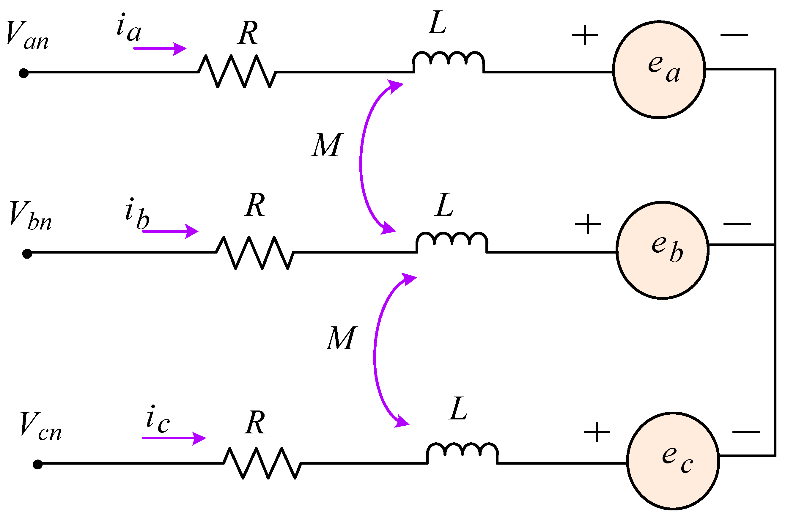
The BLDC motor has a permanent magnet-mounted, three-phase symmetrical winding stainless-steel rotor. Because stainless steel and permanent magnets have high resistance, rotor current is ignored [46]. As shown in Figure 3, the basic equivalent circuit of a BLDC motor’s armature voltage can be configured.
Three-phase synchronous motor modeling can be used to compare BLDC motor modeling [47]. The following mathematical equation can be utilized to represent the basic governing equations of armature voltage in a BLDC motor.
V a = L d i a d t + R · i a + e a
V b = L d i b d t + R · i b + e b
V c = L d i c d t + R · i c + e c
where L is the self-inductance and R is the resistance of each phase winding.
The following form can be used to rewrite Equations (1)–(3):
V a n V b n V c n =   R 0 0 0 R 0 0 0 R     i a i b i c + L a L a b L a c L b a L b L b c L c a L c b L c   p   i a i b i c + e a e b e c
where p is number of poles
If the phase winding resistances are equal, the iron loss is low. There is no mutual inductance between phase’s windings, and the self-inductance is constant, and it decreases.
L a = L b = L c = L
L b a = L b c = L c a = M = 0
V a V b V c = R   i a i b i c + L p   i a i b i c + e a e b e c + V n V n V n  
The non-conducting phase’s back EMF is given by:
e a = k e   f θ e   ω r
e b = k e   f θ e 2 π 3   ω r
e c = k e   f θ e + 2 π 3   ω r
where k e is the back EMF constant = 0.06 V/Rad/s
The following is the torque equation.
T e = e a · i a + e b · i b + e c · i c w r
T e = T l + J d w d t + B w
T e = K τ × I
where is the torque constant in [N⋅m⋅A]. The output power is:
P = T e · ω r
Newton’s second law is applied to the rotating motion of the BLDC motor to complete the mathematical model, as follows:
TeTl = J d/dt ωr + βωr
where Tl refers to the load torque, ωr angular velocity, and J the moment of inertia and coefficient of viscous friction. The electrical torque Te and its equation can be derived from an energy balance viewpoint, where the power supplied to the rotor (electromagnetic power) is equal to the product of the currents and the EMFs of the three phases, or the sum of the two, i.e.,
Pe = [ ea eb ec ]   i a i b i c
All electromagnetic energy is converted to kinetic energy if mechanical losses are ignored.
Pe = Te ωr
Electrical torque Te is explained by:
Te = P 2   K   f θ   f θ 2 π 3   f θ + 2 π 3 F T   i a i b i c
Figure 4 shows a schematic design of a BLDC motor with three phases. This diagram shows the dependence on the BLDC motor’s speed response.

2.1. Dynamic Model

The closed-loop speed control system of the drive controller BLDCM is constructed using the original dynamic mathematical model, and the structure is illustrated in Figure 5. The regulator, using the pulse width modulator (PWM), the speed feedback network, the BLDCM, and the three-phase inverter, makes up the majority of the device.
A list of differential equations is established in accordance with the equivalent circuit of the BLDCM. Use the Laplace transformation to obtain the voltage and current transfer functions under the initial condition of zero initial states:
I d ( s ) U d o ( s ) = 1 / R T 1 s + 1
Moreover, current and electromotive have the following transfer function:
E ( s ) I d s I d l ( s ) = R T m   s
A dynamic structure of BLDCM is obtained by combining (19) and (20).
Two inputs are present: a load current IdL and voltage for a light rectifier that is ideal for Udo. The former, however, is a disturbance input, the latter a control input. The electromagnetic time constant is called Tl. Tm is the electric traction system’s mechanical and electrical time constant. Ce is the coefficient of the counter-electromotive force (EMF) [48].

2.2. Design of Speed Control

PI controllers are used for HEV speed control and BLDC motor current control to ensure EV traction. The PI speed and current controllers were tuned using classical methods based on trial and error. Intelligent tuning algorithms were used. The last two algorithms gave better results and a good compromise between speed and power control, which was the main problem of the trial-and-error method. An electric vehicle was simulated against a simple input speed criterion and an international driving cycle. Simulation results show that applying a field-oriented control FOC technique in conjunction with efficient regulation of speed and current loops yields satisfactory speed and torque results. A robustness analysis was performed, and the results show that the HEV is robust to variations in environmental parameter.
The block design shown in Figure 6 incorporates the acquisition to control the commutations. Back electromotive force is referred to as back EMF. The back EMF, to put it simply, is an electromotive force in place while the brushless motor rotates. The BEMF has zero-crossing detection. Based on zero-crossing time intervals, the motor speed is hypothesized. The speed PI controller receives input from the discrepancy between the requested and estimated speeds. The voltage to be provided to the brushless direct current motor is directly proportional to the result of the speed PI controller [49].
To provide feedback to the current controller, the BEMF zero-crossing event includes measurement and filtering of the motor current. The existing output of the PI controller constrains the output of the speed PI controller. The maximum permitted motor current is protected from being exceeded by the speed PI controller’s output limiting.

3. Control Methodology and Problem Formulation

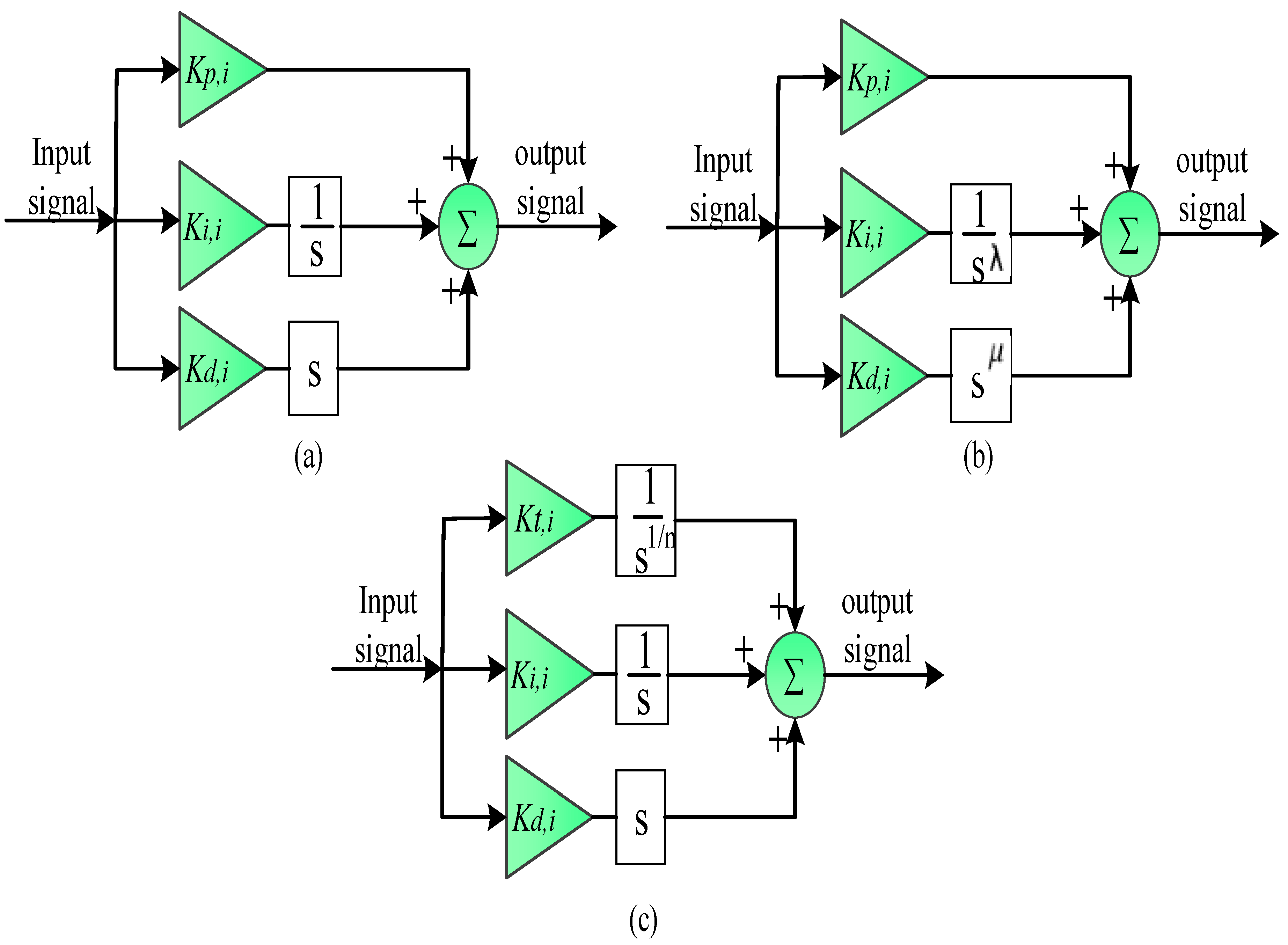
Manufacturers appreciate the PID and its different forms due to its reliability, simpler dynamic modeling, ease of construction, no need for great user expertise, and low cost-to-performance ratio. In this regard, the FOPID is considered an FO form of PID controller that offers more degrees of freedom and maintains more dynamic performance than a PID controller. This returns to the non-integer gains: the FOPID controller’s integral and derivative orders are not integers (e.g., fractional order of integrator (λ) and fractional order of derivative (µ)).
Furthermore, the TID controller’s structure is derived from fractional-order calculus, making it a fractional order controller (FOC). The construction of a TID controller is identical to that of a PID controller, with the exception that a (1/s^(1⁄n)) transfer function is used to weight the proportional parameter. The TID controller gains several advantages from this weighted transfer function, such as easier tuning, better rejection of fluctuations, and increased sensitivity due to system parametric fluctuations. The structure of the controllers discussed is shown in Figure 7.
According to Figure 7, the PID controller has three gains—proportional, integral, and derivative— and the output signal is expressed according to the following relationship:
U C S = [ K p + K I s + K d s ] E ( s )
Here, K p , K I and K d are the proportional, integral, and derivative gains, respectively. A PID controller’s performance is strongly reliant on the proper adjustment of its gain parameters. Tuning the gains can decrease overshoot, settle time, and steady-state error while reducing extreme oscillations or instability during the tuning process. Tuning the PID settings can be difficult, especially in complicated systems. It frequently necessitates specialized expertise. Poor control, oscillations, or instability can result from insufficient tuning.
Additionally, as shown in Figure 7, the transfer function of the TID controller can be expressed as follows:
U C S = [ K T S 1 n + K I S + K d S ] E ( s )
where “n” is a positive real number (it is recommended to choose a value of “n” within the range of 1 to 10).
In this regard, the TID controller is applied to the considered model to enhance its performance, e.g., torque and speed. This control system manages the torque output, speed, and position of the motor to ensure precise and efficient operation in various applications, such as power steering, braking systems, cooling systems, HVAC systems, propulsion systems, and actuators. TID control is essential for optimizing the performance of BLDC motors in electric vehicles and ensuring smooth and reliable operation.

4. Simulation of Proposed System

Modeling the BLDC motor drive system using MATLAB/Simulink is a common and effective approach. This allows for the creation of a detailed and accurate simulation of the system’s behavior, enabling analysis, design, and testing of control algorithms and power electronics components.

4.1. Modeling of BLDC Drive

The BLDC motor drive is modeled using MATLAB/Simulink. This system is composed of a battery as a power source, three-phase inverter and BLDC motor. In this system, the battery serves as the power source, providing the necessary electrical energy to drive the three-phase inverter. The inverter, in turn, converts the DC power from the battery into three-phase AC power, which is then supplied to the BLDC motor. The motor utilizes this electrical power to produce mechanical motion.
Using MATLAB/Simulink, we can create a comprehensive model that includes the dynamics of the battery, the switching behavior of the inverter, and the electromechanical characteristics of the BLDC motor. Additionally, control algorithms such as field-oriented control or sensor-less control can be implemented and tested within the simulation environment.
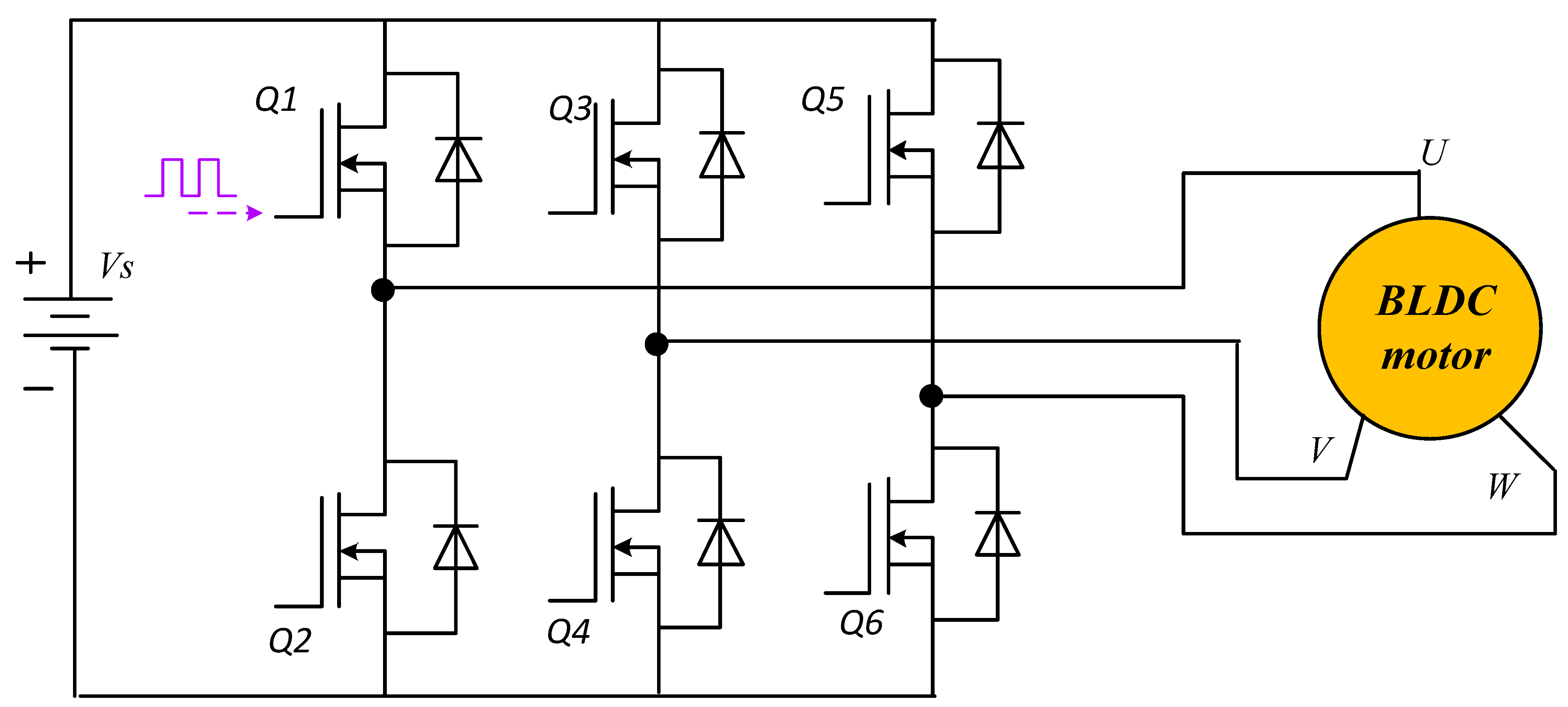
Inverter modeling with a 120° conduction mode is implemented in MATLAB-Simulink (see Figure 8). For each of the six transportation sectors, the inverter model is derived, since the inverter control employs information from Hall effect sensors. The MATLAB blocks are used to determine the latter.
Hall sensors detect coil placement and decoder circuit, coil position activates and deactivates the relevant switches, and the motor is rotated by the voltage passing through the appropriate coils in the BLDCM works. BLDC typically employs three phases, with 120 degrees between each phase’s conducting intervals. An electronic speed controller controls a brushless motor’s movement or speed by turning on the necessary MOSFETs, which cause the motor to rotate. The frequency and speed are adjusted over the six periods and determine how fast the motor will move. The simulation parameters of the BLDC motor and battery are given in Table 2.
By simulating the entire system in MATLAB/Simulink, we can analyze its performance under various operating conditions, design, and tuning control strategies and evaluate the impact of different parameters such as load torque, speed references, and disturbances. This approach provides valuable insights into the behavior of the BLDC motor drive system, helping to optimize its performance and efficiency before implementation in real-world applications.

4.2. Simulation Results

Drive cycle control of BLDC motors refers to the specific pattern or sequence in which the motor’s coils are energized to drive the motor’s rotation. This control method involves determining the optimal timing and duration for energizing each coil to achieve the desired speed, torque, and efficiency of the motor. By carefully controlling the drive cycle, the motor can operate more efficiently and with greater precision, making it suitable for a wide range of applications. This control method is often used in conjunction with other control techniques, such as FOC or DTC, to achieve the best overall performance of the BLDC motor.
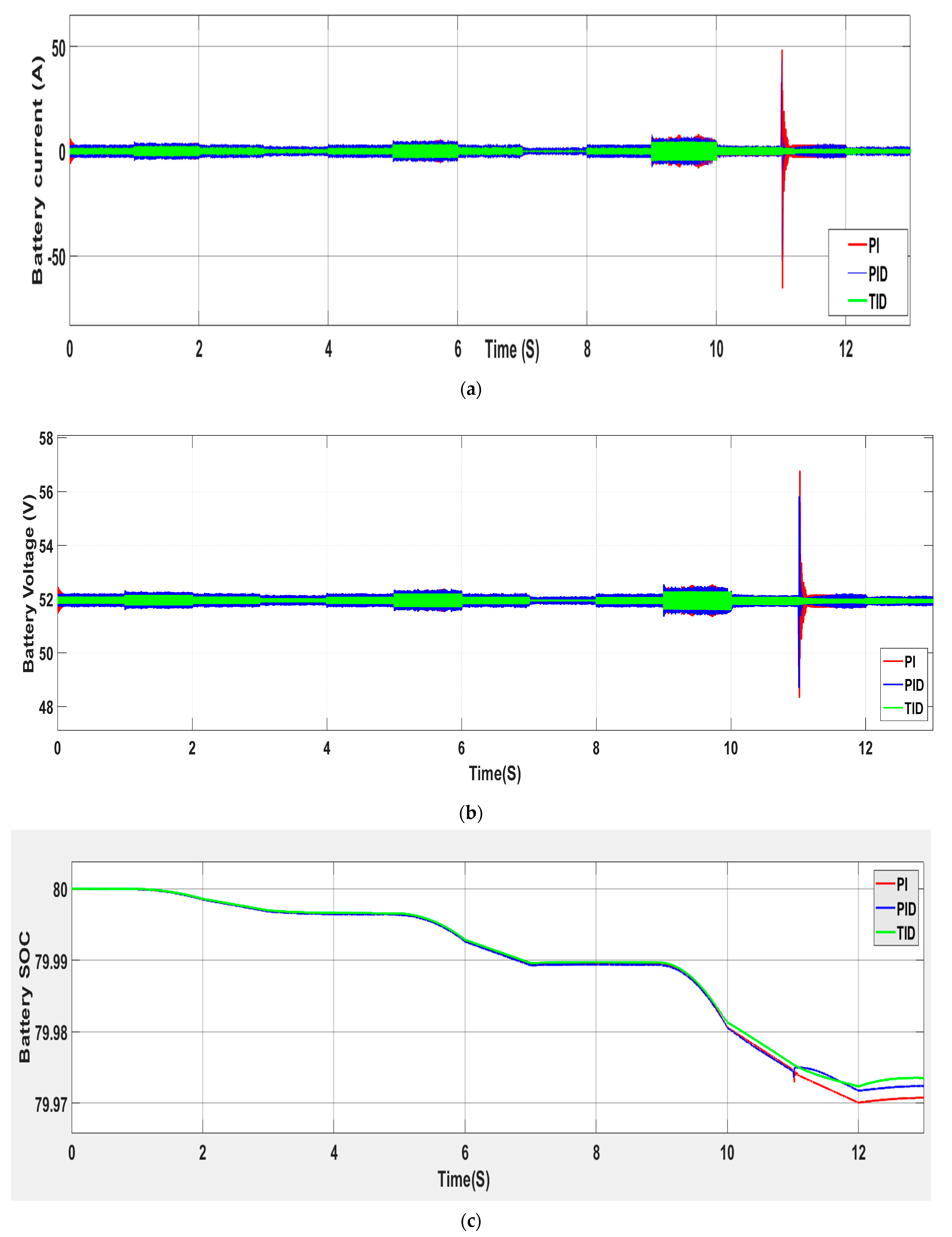
Figure 9 shows the simulated battery current, voltage and SOC. The battery voltage and current are improved due to using TID control. There are no spikes in the voltage or current signals. Moreover, the SOC is increased using TID after 10 s of simulation. Simulated input power is displayed in Figure 10. There is an overshot in the power curve due to input voltage and current spikes. The overshot in the power curve displayed in Figure 10 is likely a result of input voltage and current spikes. These spikes can occur due to sudden changes in the motor load, rapid changes in the control signals, or other transient disturbances in the system. When there are sudden changes in the motor load, the input power to the BLDC drive can experience spikes as the drive responds to the new load conditions. Similarly, rapid changes in control signals, such as those caused by switching between different control modes or setpoints, can also lead to spikes in input voltage and current, resulting in overshoot in the power curve. TID control can help minimize these spikes and improve the overall stability of the system. By addressing these issues, it is possible to achieve smoother and more stable input power characteristics, leading to improved efficiency and performance of the BLDC drive.
Results are compared in cases of PI, PID and TID controllers. The stator currents in a BLDC motor are crucial for controlling the motor’s speed, torque, and efficiency. Three-phase stator currents are shown in Figure 11. The currents in the motor’s stator windings are responsible for creating the magnetic fields that interact with the rotor to produce motion. By carefully controlling the amplitude and timing of these currents, the motor can be optimized for various operating conditions.
Figure 12 shows the back EMF of BLDC motor. Back EMF (electromotive force) of a BLDC (brushless DC) motor is the voltage that is induced in the motor’s windings when the rotor is turning. This back EMF is proportional to the speed of the motor and opposes the applied voltage, effectively acting as a counter-electromotive force. It is an important factor in controlling the speed and position of the motor, and it is often used in sensor-less control algorithms to determine the rotor position and commutation timing.
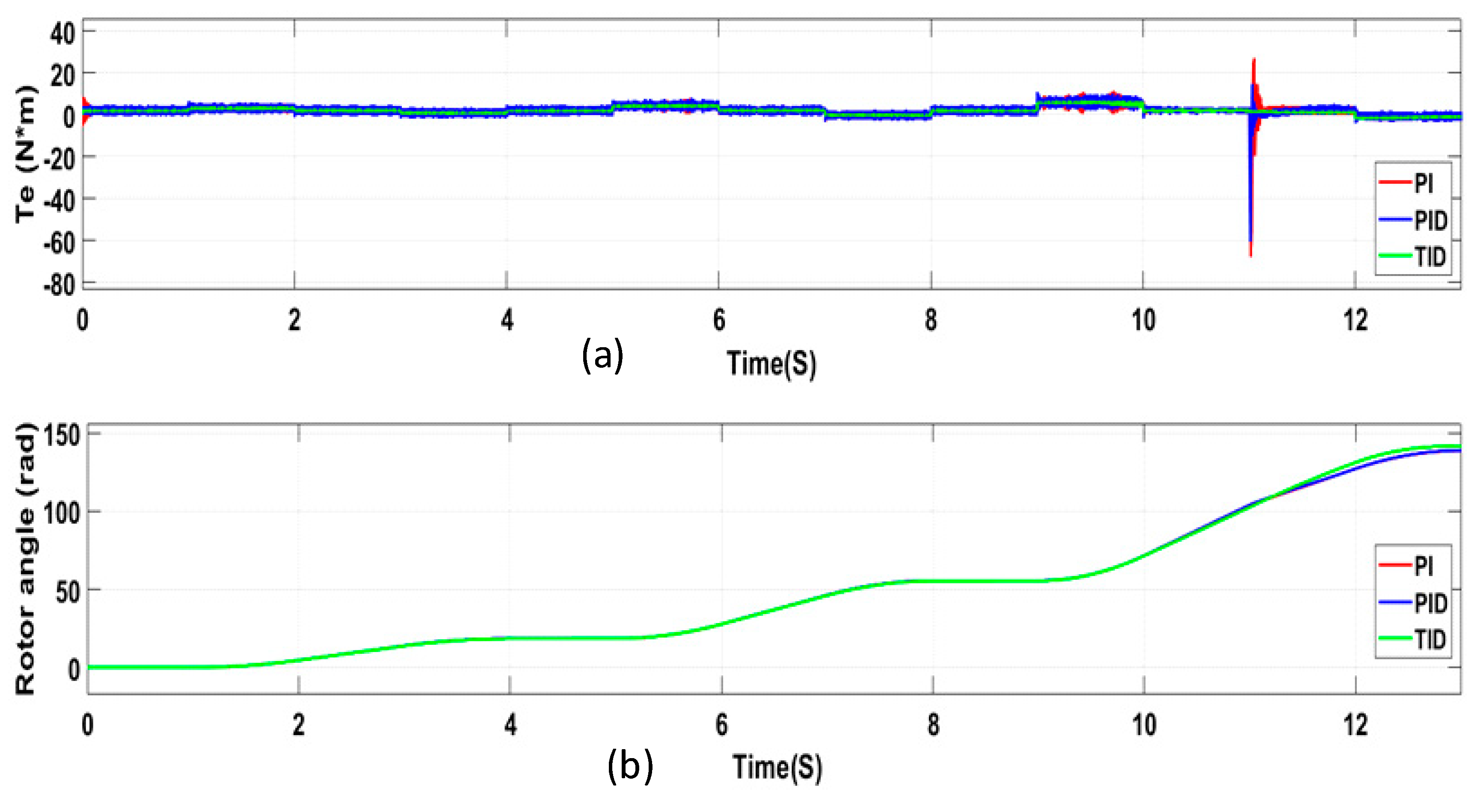
The electromagnetic torque of the BLDC motor is displayed in Figure 13a. The rotor angle of a BLDC motor is also crucial for controlling the motor’s performance. The rotor angle determines the position of the rotor relative to the stator windings, and it is essential for accurate commutation and torque production. Figure 13b shows the simulated rotor angles a, b, and c. In order to effectively control the rotor angle, sensor feedback or sensor-less techniques can be used. Sensor feedback involves using position sensors, such as Hall effect sensors or encoders, to accurately determine the rotor angle. Sensor-less techniques, on the other hand, use algorithms to estimate the rotor angle based on the back electromotive force (EMF) of the motor. Accurate control of the rotor angle allows for precise commutation and torque production, leading to improved efficiency and performance of the BLDC motor. Additionally, advanced control algorithms can further optimize the rotor angle for specific operating conditions, making the motor suitable for a wide range of applications.
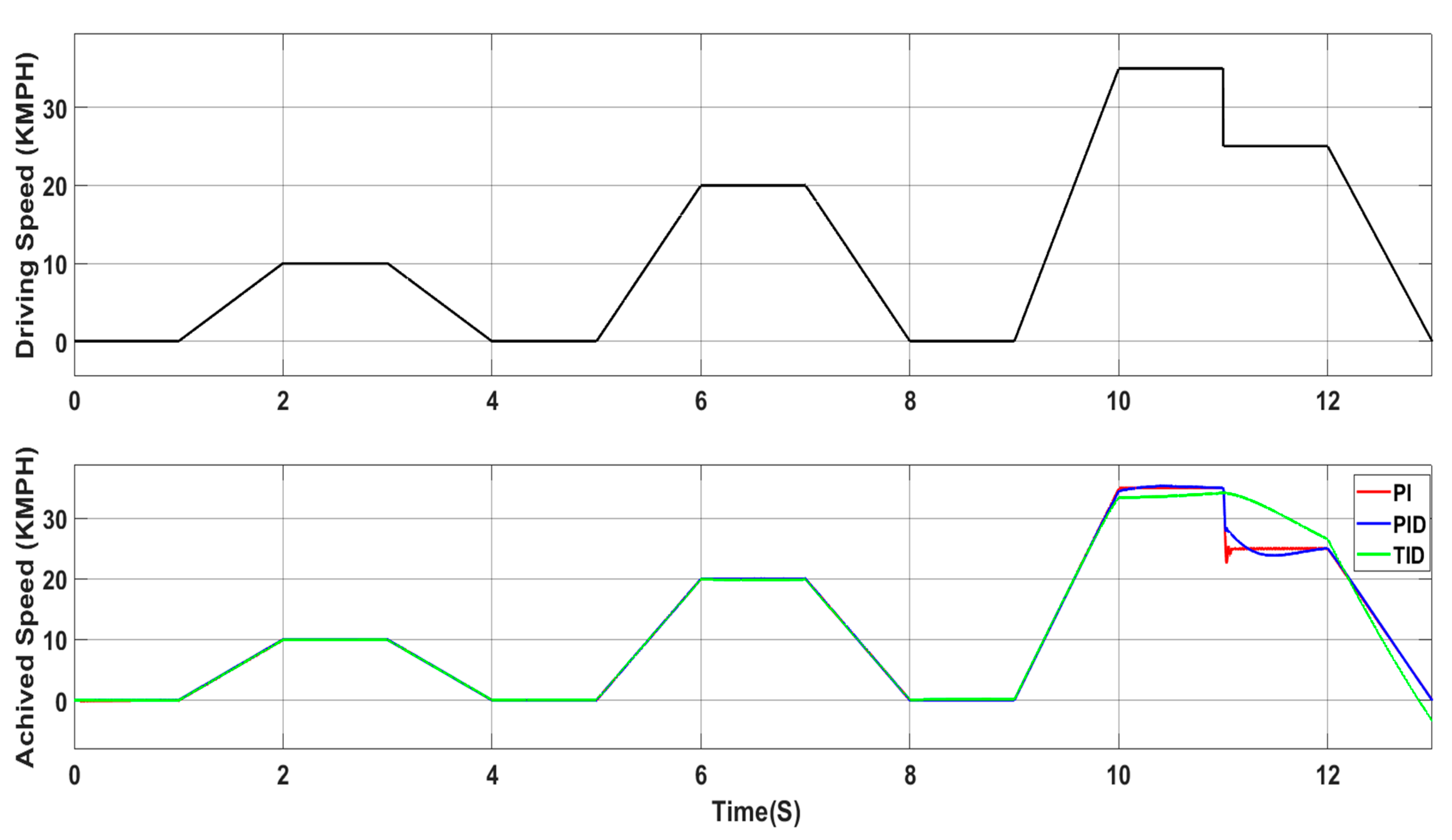
The simulated driving cycle speed is displayed in Figure 14. When utilizing TID control instead of PI and PID control, a faster speed is attained. The gate signal applied to the three-phase bridge switches in Figure 15 is what makes them move at the necessary pace.

5. Experimental Setup

The experiment was constructed and the required circuit was welded successfully, as shown in Figure 16a,b. Then, the final shape of the board of the BLDC motor circle was attained, as shown in Figure 16.
A PWM signal is generated with a duty cycle ranging from 0% to 100%, and a frequency of 50 Hz is required. A potentiometer should be used to regulate the duty cycle to regulate the motor’s speed. Since controlling the motors similarly requires a PWM signal with a frequency of 50 Hz, the code is similar to that used to control the motors, so the same library from the Arduino platform is used.
The experimental setup using an Arduino UNO controller is shown in Figure 17a, while the whole system setup is shown in Figure 17b. The BLDC motor was connected to the designed circuit and tested by connecting the voltage. The start of the experiment was at 12 V, but the motor had not started. As such, the circuit was tested again in the lab by coding Arduino with it plugged into the laptop and uploading the code to the Arduino (UNO) chip. The BLDC motor is wound at a very high speed, ranging from 2200 rpm to 2500 rpm.
A commutation check is necessary first. To generate motion, a three-phase linear motor must switch between the phases and engage the appropriate windings. The change between the three phases is referred to as commutation. The motor can be made to turn to a specific position by turning on one pole at a time or by simply measuring the voltage at the motor.
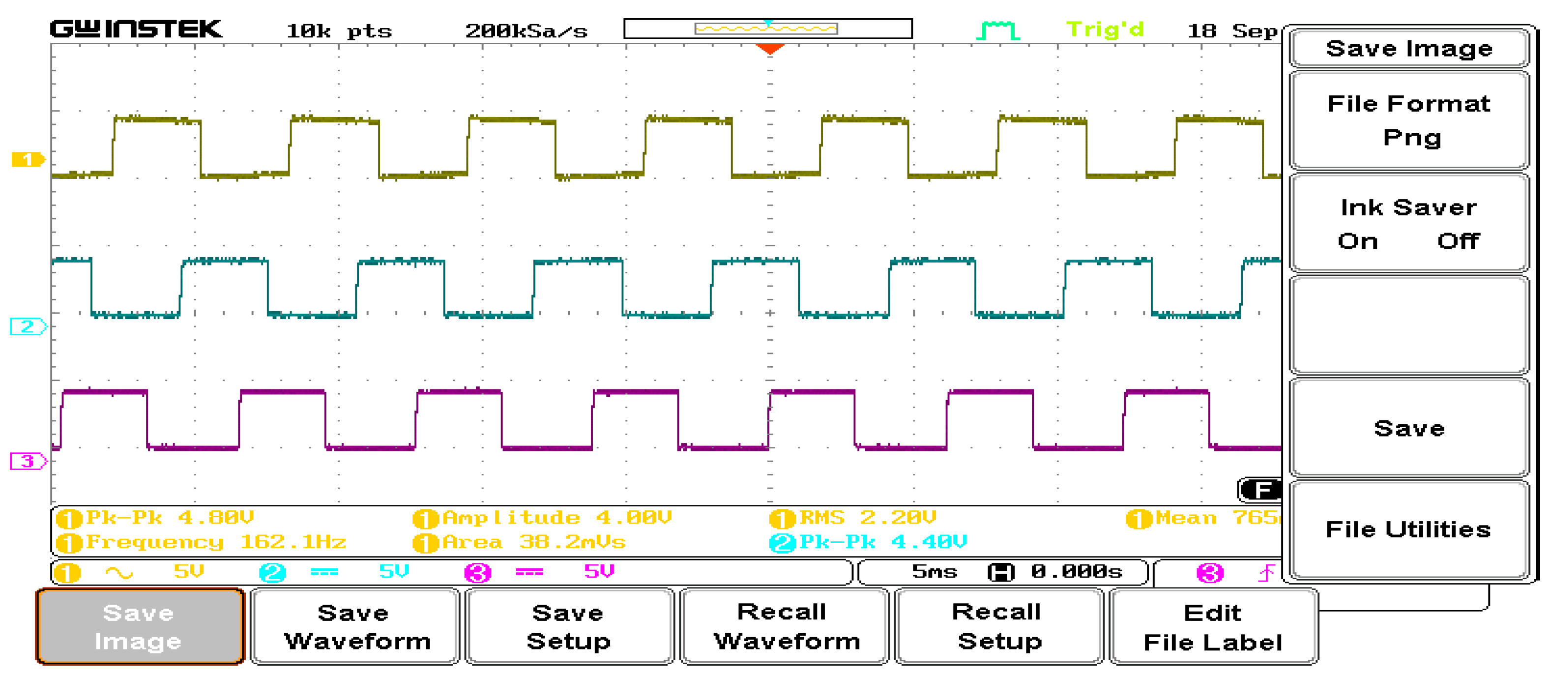
In order to determine the motor’s speed, a brushless DC motor was installed in a specific manner, either by utilizing a mounting device or by fixing the motor to a wooden board. The experimental phase voltages for phases A and B are shown in Figure 18. The experiment’s outcomes coincide with the simulation.
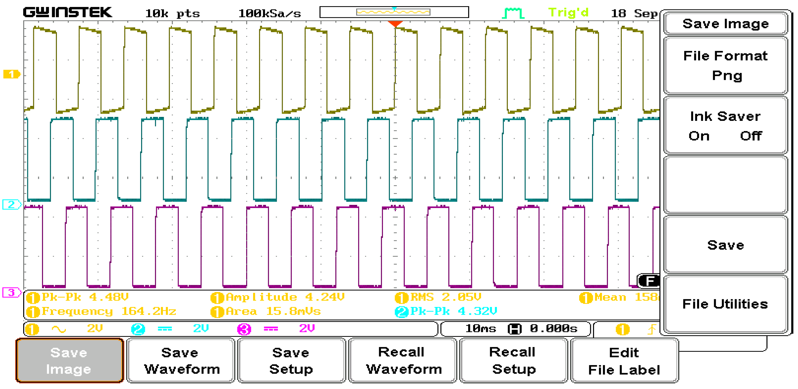
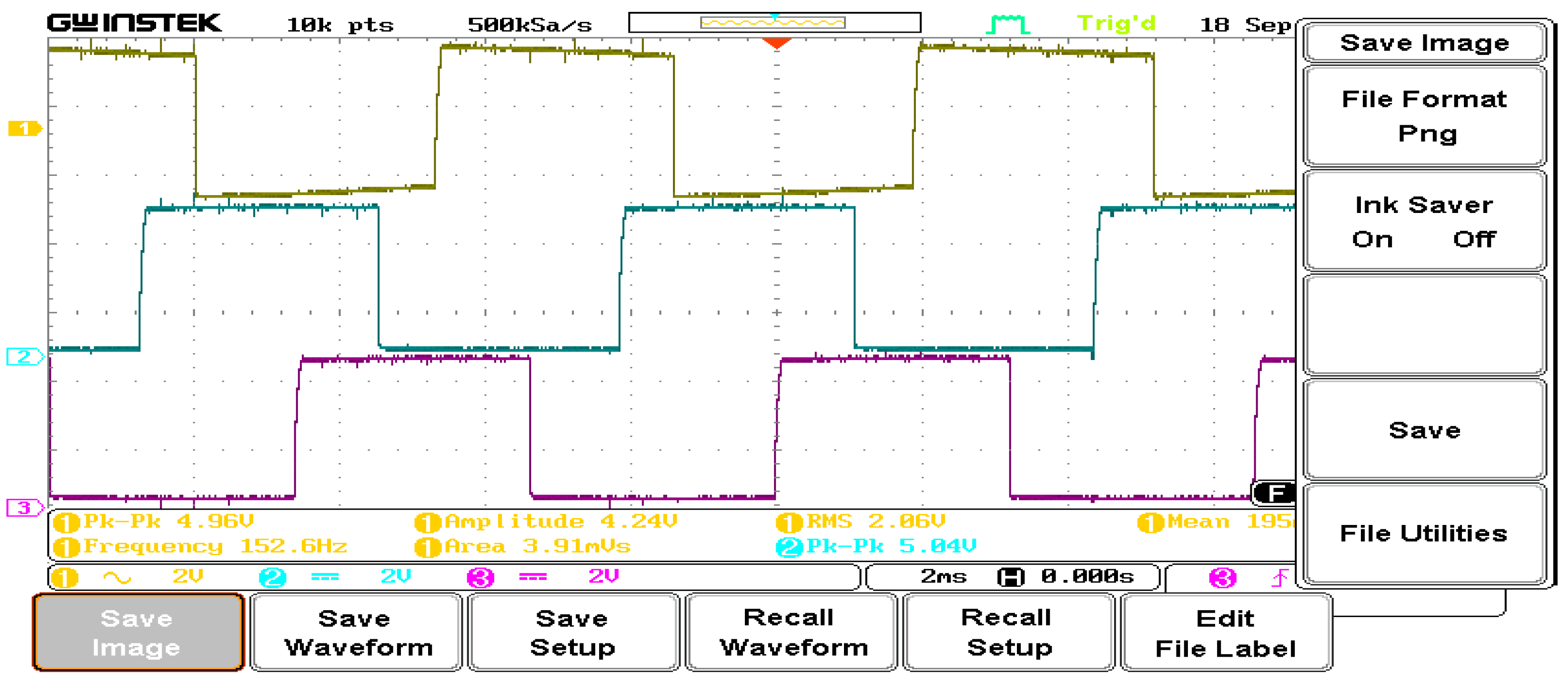
The experimental phase voltages for phases a, b, and c are phase-shifted by 120 degrees using an Ardino UNO. Figure 18 depicts the motor at its highest speed and illustrates a phase-shift of 120 degrees between phases. Figure 19 illustrates the waveforms as the speed is gradually decreased. The experimental voltage waveform of phases A, B, and C is shown in Figure 20 at a very slow speed. Three sinusoidal waveforms that are 120 degrees out of phase with one another are commonly visible in three-phase waveforms obtained from a BLDC motor drive. The voltages applied to each motor phase are seen in these waveforms.
The waveforms typically have a constant frequency and amplitude, and they are symmetrical and balanced. Waveform features and shape can reveal important details regarding the functionality and condition of the motor drive system. These waveforms can be analyzed to help find faults that could impair the motor’s performance, such as phase imbalances, voltage anomalies, or other concerns. The simulated and experimental results are somewhat consistent.
During a change in BLDC motor speed, the frequency of the switching operation in the motor drive is also varied. This is because the speed of the motor is directly related to the frequency at which the power electronic switches (such as MOSFETs or IGBTs) in the motor drive are turned on and off to generate the three-phase AC voltage waveforms. As the motor speed increases, the frequency of the switching operation also needs to increase to maintain the appropriate timing for the generation of the sinusoidal waveforms. Conversely, when the motor speed decreases, the switching frequency will need to decrease accordingly.
Therefore, changes in motor speed will result in corresponding adjustments to the switching frequency of the power electronic devices in the motor drive to ensure that the correct voltage waveforms are applied to the motor phases, enabling smooth and efficient operation across different speed ranges.

6. Stability Analysis

The stability of a BLDC motor drive can be checked using various methods and techniques. In this paper, stability analysis of a BLDC motor drive is determined by two methods. First, the relative stability of this drive system is determined by Bode plot. The second method is using a pole-zero map to check the stability of a control system.

6.1. Bode Plot

The analyses spotlight that it is possible to obtain a finite-time setting response without oscillation in the BLDC motor drive by applying input in four steps of different amplitude to the drive system. These analyses are helpful to design a precise speed control system and current control system for the BLDC motor drive with fast response. Generating Bode plots of the open-loop transfer functions of the control loops (e.g., current loop, speed loop) can provide insights into the system’s stability characteristics. Bode plots can reveal gain and phase margins, as well as resonant frequencies and other important system parameters. Figure 21 shows the Bode plot of the BLDC drive studied in this paper. This figure proves that the system is stable.

6.2. Pole-Zero Map

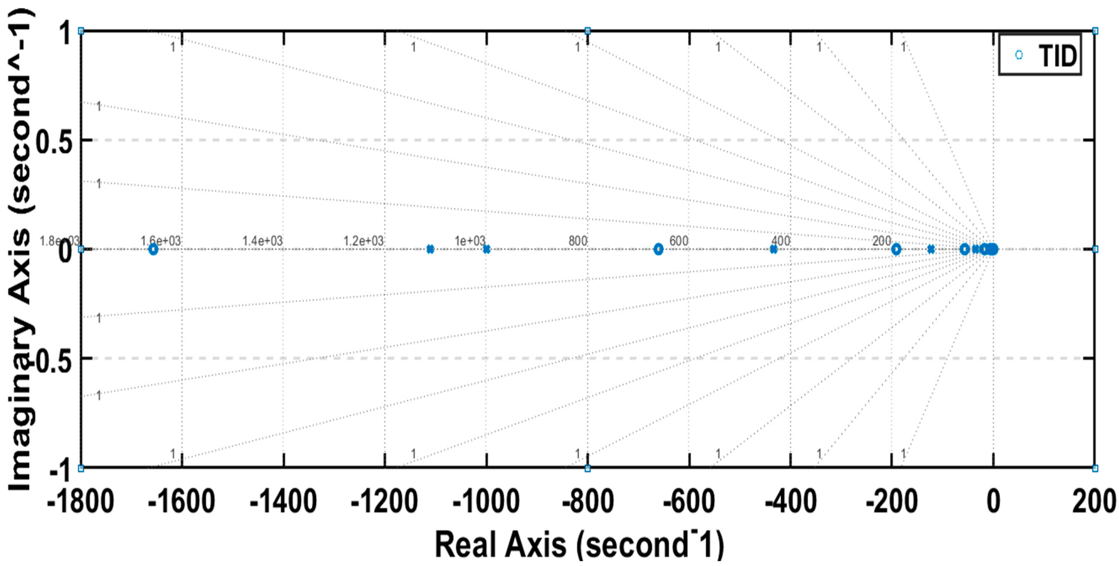
To begin this method, the poles and zeros of the transfer function are determined, with the poles representing the values of s for which the denominator of the transfer function becomes zero, and the zeros representing the values of s for which the numerator becomes zero. Following this, the poles and zeros are plotted on the complex plane, which consists of a real axis (horizontal) and an imaginary axis (vertical), with each pole and zero corresponding to a point on the complex plane based on its real and imaginary parts. Subsequently, the pole-zero map is analyzed to determine the stability of the system, with a stable system having all its poles in the left half of the complex plane (i.e., with negative real parts), while an unstable system would have at least one pole in the right half of the complex plane (i.e., with a positive real part).
Figure 22 demonstrates that the system is stable, because all poles are located in the left half of the complex plane.

7. Discussion

Advantages of TID control for BLDC in electric vehicle can be summarized as follows.
  • Precise control: TID control allows for precise and accurate regulation of torque, speed, and position of the BLDC motor, resulting in smooth and efficient operation of the electric vehicle.
  • Energy efficiency: By optimizing the performance of the motor, TID control helps in maximizing energy efficiency, which is crucial for extending the range of electric vehicles and reducing energy consumption.
  • Enhanced performance: TID control ensures that the motor operates at its optimal performance levels, leading to improved acceleration, braking, and overall vehicle dynamics.
  • Reduced wear and tear: By controlling the torque output and speed of the motor, TID control helps in minimizing wear and tear on the motor and other vehicle components, leading to increased longevity and reduced maintenance costs.
  • Flexibility: TID control can be tailored to suit different driving conditions and requirements, allowing for flexibility in adapting to various applications and driving scenarios.
  • Safety: Precise control over the motor’s torque, speed, and position can contribute to enhanced safety by ensuring stable and predictable vehicle behavior in different driving situations.
  • Smooth operation: TID control helps in achieving smooth and seamless operation of the electric vehicle, providing a comfortable and enjoyable driving experience for the occupants.
Many works have proposed PI and PID control [8,9,10,11,19,32,39,40,41,42,43,44,45], but none has proposed a TID for a BLDC drive. In comparison to PI and PID controllers, TID controllers offer improved input power for BLDC (brushless DC) drives. TID controllers are designed to provide better transient response and robustness to disturbances, which can result in more efficient use of input power. This improved performance can lead to better overall system efficiency and responsiveness, making TID controllers a favorable option for BLDC drive applications.
The tilt integral derivative (TID) control method is a variation of the PID control used for BLDC motor speed regulation. It offers several potential advantages, including improved transient response, reduced steady-state error, and robustness to parameter variations and disturbances. TID control can provide better transient response, particularly in systems with significant load disturbances or sudden changes in operating conditions. It also helps minimize steady-state error, enhancing speed regulation and accuracy, which is crucial in applications requiring precise speed control. Additionally, TID control offers robustness to parameter variations and disturbances, making it suitable for applications where the motor may operate in varying conditions. However, TID control may require more complex tuning compared to traditional PID control, and it may be more sensitive to noise and measurement errors due to its increased complexity.
TID control, a variation of PID control for BLDC motor speed regulation, has several disadvantages. Firstly, it is more complex to implement and requires more intricate tuning and design, making the process challenging. Additionally, TID control is sensitive to noise and measurement errors, particularly in the derivative term, which can lead to instability if not properly addressed. Moreover, it increases the computational burden compared to PID control, requiring more processing power, especially in embedded systems or applications with limited computing capabilities. Tuning a TID controller is also more challenging due to the increased number of parameters and interactions among them, necessitating more expertise and time. While TID control offers potential advantages, such as improved transient response and reduced steady-state error, its drawbacks related to complexity, sensitivity to noise, computational burden, and tuning should be carefully considered when deciding whether to use it for BLDC motor speed control.

8. Conclusions

In order to improve real-time control of BLDC motors for electric vehicles, a new TID control method has been implemented to enhance system performance. The results from simulations and experiments show that the optimized BLDC drive system, as indicated by the waveforms generated from the final simulation, exhibits stable speed without overshooting under TID control. Moreover, the state of charge (SOC) of the electric vehicle battery improved with the use of TID control. These findings highlight the significant benefits of the suggested BLDC motor for electric vehicle applications, offering high efficiency and contributing to clean and safe transportation.
The experimental validation demonstrates the success of the proposed controller in electric vehicle applications. The control strategies were rigorously examined and tested, both in an experimental lab and on the MATLAB software platform. A specialized test bench was constructed to enhance power electronics and real-time control of BLDC motors, with a focus on PWM techniques and speed control in both theory and practice. The control scheme implementation utilized PWM techniques with both soft switching and hard switching. The Arduino motors were controlled by the BLDC platform to generate a PWM signal with a duty cycle ranging from 0% to 100% and a frequency of 50 Hz. An experimental prototype using identical circuit settings as in the simulation was developed to validate the simulation results.

Author Contributions

Conceptualization, K.S. and A.A.; methodology, H.H.E.-Z.; software, M.K.; validation, K.S., H.H.E.-Z. and M.K.; formal analysis, K.S.; investigation, H.H.E.-Z.; resources, H.H.E.-Z.; data curation, A.A.; writing—original draft preparation, A.A.; writing—review and editing, M.K.; visualization, H.H.E.-Z.; supervision, A.A.; project administration, A.A.; funding acquisition, M.K. All authors have read and agreed to the published version of the manuscript.

Funding

This paper is based upon work supported by the Science, Technology and Innovation Funding Authority (STDF) under grant 45039.

Data Availability Statement

The supporting data of this article will be made available by the authors on request.

Conflicts of Interest

The authors declare no conflicts of interest.

References

  1. Chow, C.C.T.; Ainslie, M.D.; Chau, K.T. High temperature superconducting rotating electrical machines. An overview. Energy Rep. 2023, 9, 1124–1156. [Google Scholar] [CrossRef]
  2. Yang, D.; Huo, Y.; Zhang, Q.; Xie, J.; Yang, Z. Recent advances on air heating system of cabin for pure electric vehicles. A review. Heliyon 2022, 8, e11032. [Google Scholar] [CrossRef]
  3. Rajesh, P.; Shajin, F.H.; Rajani, B.; Sharma, D. An optimal hybrid control scheme to achieve power quality enhancement in microgrid connected system. Int. J. Number Model Electron. Netw. Dev. Fields 2022, 35, e3019. [Google Scholar] [CrossRef]
  4. Jayakumar, V.; Chokkalingam, B.; Munda, J.L. A Comprehensive Review on Space Vector Modulation Techniques for Neutral Point Clamped Multi-Level Inverters. IEEE Access 2021, 9, 112104–112144. [Google Scholar] [CrossRef]
  5. Aliasand, A.E.; Josh, F. Selection of motor for an electric vehicle. A review. Mater. Today Proc. 2020, 24, 1804–1815. [Google Scholar] [CrossRef]
  6. Manuel, N.L.; İnanç, N.; Lüy, M. Control and performance analyses of a DC motor using optimized PIDs and fuzzy logic controller. Results Control Optim. (RICO) 2023, 13, 100306x. [Google Scholar] [CrossRef]
  7. Chen, Q.; Liu, G.; Zhao, W.; Qu, L.; Xu, G. Asymmetrical SVPWM fault-tolerant control of five-phase PM brushless motors. IEEE Trans. Energy Convers. 2016, 3, 12–22. [Google Scholar]
  8. Sriram, J.; Sureshkumar, K. Speed control of BLDC motor using fuzzy logic controller based on sensorless technique. In Proceedings of the International Conference on Green Computing Communication and Electrical Engineering (ICGCCEE), Coimbatore, India, 6–8 March 2014; pp. 1–6. [Google Scholar]
  9. Goswami, R.; Joshi, D. Performance review of fuzzy logic based controllers employed in brushless DC motor. Procedia Comput. Sci. 2018, 132, 623–631. [Google Scholar] [CrossRef]
  10. Yong, Z.; Man, W.; Qi, L.; Chao, Z. The design of BLDCM controller for EMA based on fuzzy PID control. In Proceedings of the Chinese Control and Decision Conference (CCDC), Yinchuan, China, 28–30 May 2016; pp. 6428–6432. [Google Scholar]
  11. Devi, K.S.; Dhanasekaran, R.; Muthulakshmi, S. Improvement of speed control performance in BLDC motor using fuzzy PID controller. In Proceedings of the International Conference on Advanced Communication Control and Computing Technologies (ICACCCT), Ramanathapuram, India, 25–27 May 2016; pp. 380–384. [Google Scholar]
  12. Whittingham, M.S. History, evolution and future status of energy storage. Proc. IEEE 2012, 100, 1518–1534. [Google Scholar] [CrossRef]
  13. Zhang, W.; Xu, Y.; Tian, X.; Nguyen, N.K.; Semail, E. Dynamic equivalent magnetic network model and drive system of permanent magnet synchronous motor with double V-shaped magnet structure. Mechatronics 2023, 96, 103091. [Google Scholar] [CrossRef]
  14. Ahmed, N.M.; Ebeed, M.; Magdy, G.; Sayed, K.; Gamoura, S.C.; Metwally, A.S.M.; Mahmoud, A.A. A New Optimized FOPIDA-FOIDN Controller for the Frequency Regulation of Hybrid Multi-Area Interconnected Microgrids. Fractal Fract. 2023, 7, 666. [Google Scholar] [CrossRef]
  15. Sayed, K.; Almutairi, A.; Albagami, N.; Alrumayh, O.; Abo-Khalil, A.G.; Saleeb, H. A Review of DC-AC Converters for Electric Vehicle Applications. Energies 2022, 15, 1241. [Google Scholar] [CrossRef]
  16. Almutairi, A.; Sayed, K.; Albagami, N.; Abo-Khalil, A.G.; Saleeb, H. Multi-Port PWM DC-DC Power Converter for Renewable Energy Applications. Energies 2021, 14, 3490. [Google Scholar] [CrossRef]
  17. Chen, W.; Mao, Z.; Tian, W. Water cooling structure design and temperature field analysis of permanent magnet synchronous motor for underwater unmanned vehicle. Appl. Therm. Eng. 2023, 240, 122243. [Google Scholar] [CrossRef]
  18. Hemalatha, N.; Venkatesan, S.; Kannan, R.; Kannan, S.; Bhuvanesh, A.; Kamaraja, A. Sensorless speed and position control of permanent magnet BLDC motor using particle swarm optimization and ANFIS. Meas. Sens. 2023, 31, 100960. [Google Scholar] [CrossRef]
  19. Intidam, A.; El Fadil, H.; Housny, H.; El Idrissi, Z.; Lassioui, A.; Nady, S.; Jabal Laafou, A. Development and Experimental Implementation of Optimized PI-ANFIS Controller for Speed Control of a Brushless DC Motor in Fuel Cell Electric Vehicles. Energies 2023, 16, 4395. [Google Scholar] [CrossRef]
  20. Skvarenina, T.L. The Power Electronics Handbook; CRC Press: Boca Raton, FL, USA, 2018. [Google Scholar]
  21. Meng, B.; Zhou, Z.; Zhang, C.; Yang, F. A design method for booster motor of brake-by-wire system based on intelligent electric vehicle. Green Energy Intell. Transp. 2023, 2, 100110. [Google Scholar] [CrossRef]
  22. Chan, C.; Chau, K. Modern Electric Vehicle Technology; Oxford University Press: Oxford, UK, 2001; Volume 47. [Google Scholar]
  23. Chan, C. An overview of electric vehicle technology. Proc. IEEE 1993, 81, 1202–1213. [Google Scholar] [CrossRef]
  24. Rimpas, D.; Kaminaris, S.D.; Piromalis, D.D.; Vokas, G.; Arvanitis, K.G.; Karavas, C.S. Comparative Review of MotorTechnologies for Electric Vehicles Powered by a Hybrid Energy Storage System Based on Multi-Criteria Analysis. Energies 2023, 16, 2555. [Google Scholar] [CrossRef]
  25. Appelbaum, J.; Sarma, M. The operation of permanent magnet DC motors powered by a common source of solar cells. IEEE Trans. Energy Convers. 1989, 4, 635–642. [Google Scholar] [CrossRef]
  26. Dawson, C.; Bolton, H. Performance prediction of a wide-angle limited-motion rotary actuator. Proc. Inst. Electr. Eng. 1978, 125, 895–898. [Google Scholar] [CrossRef]
  27. Dawson, C.; Bolton, H. Design of a class of wide-angle limited-rotation rotary actuators. Proc. Inst. Electr. Eng. 1979, 126, 345–350. [Google Scholar] [CrossRef]
  28. Tokunaga, D.; Kesamaru, K. Development of novel PM motors for sport type electric motorcycles. In Proceedings of the 15th International Conference on Electrical Machines and Systems (ICEMS), Sapporo, Japan, 21–24 October 2012; pp. 1–4. [Google Scholar]
  29. Akhil, M.; Aishwarya, V.; Sheela, K.G. An Improved SEPIC- Based Single Switch Buck-Boost PFC Converter Fed Brushless DC Motor Drive. Mater. Today Proc. 2020, 24, 1855–1864. [Google Scholar] [CrossRef]
  30. Saleeb, H.; Kassem, R.; Sayed, K. Artificial neural networks applied on induction motor drive for an electric vehicle propulsion system. Electr. Eng. 2022, 104, 1769–1780. [Google Scholar] [CrossRef]
  31. Murai, Y.; Kawase, Y.; Ohashi, K. Torque ripple improvement for brushless DC miniature motors. IEEE Trans. Ind. Appl. 1989, 25, 441–450. [Google Scholar] [CrossRef]
  32. Park, S.I.; Kim, T.S.; Ahn, S.C.; Hyun, D.S. An improved current control method for torque improvement of high-speed BLDC motor. In Proceedings of the IEEE 18th Applied Power Electronic Conference and Exposition, Miami, FL, USA, 9–13 February 2003; pp. 294–299. [Google Scholar]
  33. Rodriguez, F.; Emadi, A. A novel digital control technique for brushless DC motor drives. IEEE Trans. Ind. Electron. 2007, 54, 365–2373. [Google Scholar] [CrossRef]
  34. Pindoriya, R.M.; Rajendran, S.; Chauhan, P.J. Field programmable gate array-based speed control of BLDC motor. In Proceedings of the IEEE Innovative Smart Grid Technologies—Asia (ISGT ASIA), Bangkok, Thailand, 3–6 November 2015; pp. 1–6. [Google Scholar]
  35. Tashakori, A.; Hassanudeen, M.; Ektesabi, M. FPGA based controller drive of BLDC motor using digital PWM technique. In Proceedings of the IEEE 11th International Conference on Power Electronics and Drive Systems, Sydney, NSW, Australia, 9–12 June 2015; pp. 658–662. [Google Scholar]
  36. Li, Z.B.; Lu, W.; Gao, L.F.; Zhang, J.S. Nonlinear state feedback control of chaos system of brushless DC motor. Procedia Comput. Sci. 2021, 183, 636–640. [Google Scholar] [CrossRef]
  37. Sayed, K.; Kassem, A.; Saleeb, H.; Alghamdi, A.S.; Abo-Khalil, A.G. Energy-Saving of Battery Electric Vehicle Powertrain and Efficiency Improvement during Different Standard Driving Cycles. Sustainability 2020, 12, 10466. [Google Scholar] [CrossRef]
  38. Elkholy, M.M.; El-Hay, E.A. Efficient dynamic performance of brushless DC motor using soft computing approaches. Neural Comput. Appl. 2020, 32, 6041–6054. [Google Scholar] [CrossRef]
  39. Premkumar, K.; Manikandan, B.V. Bat algorithm optimized fuzzy PD based speed controller for brushless direct current motor. Eng. Sci. Technol. 2016, 19, 818–840. [Google Scholar] [CrossRef]
  40. Wang, T.; Wang, H.; Wang, C.; Hu, H. A novel PID controller for BLDCM speed control using dual fuzzy logic systems with HSA optimization. Sci. Rep. 2022, 12, 11316. [Google Scholar] [CrossRef]
  41. Dat, N.T.; Cao, V.K.; Anh, H. Optimal FOC-PID parameters of BLDC motor system control using parallel PM-PSO optimization technique. Int. J. Comput. Int. Syst. 2021, 14, 1142–1154. [Google Scholar] [CrossRef]
  42. Xie, W.; Wang, J.S.; Wang, H.B. PI controller of speed regulation of brushless DC motor based on particle swarm optimization algorithm with improved inertia weights. Math. Probl. Eng. 2019, 2019, 2671792. [Google Scholar] [CrossRef]
  43. He, M.; Zhang, T.; Huang, J.; Luo, C. Speed control study of brushless DC motor based on fuzzy optimization PID. IOP Conf. Ser. Mater. Sci. Eng. 2020, 768, 042013. [Google Scholar] [CrossRef]
  44. Mu, S.; Shibata, S.; Yamamoto, T.; Nakashima, S.; Tanaka, K. Speed control of ultrasonic motor using a variable gain type PID control based on neural networks. In Proceedings of the 7th International Conference on Intelligent Systems and Image Processing, Taipei, Taiwan, 5–9 September 2019; pp. 103–108. [Google Scholar] [CrossRef]
  45. Patil, M.D.; Vadirajacharya, K.; Khubalkar, S.W. Design and Tuning of Digital Fractional-Order PID Controller for Permanent Magnet DC Motor. IETE J. Res. 2021, 69, 4349–4359. [Google Scholar] [CrossRef]
  46. Jo, S.T.; Shin, H.S.; Lee, Y.G.; Lee, J.H.; Choi, J.Y. Optimal design of a BLDC motor considering three-dimensional structures using the response surface methodology. Energies 2022, 15, 461. [Google Scholar] [CrossRef]
  47. Lee, T.Y.; Seo, M.K.; Kim, Y.J.; Jung, S.Y. Motor design and characteristics comparison of outer-rotor-type BLDC motor and BLAC motor based on numerical analysis. IEEE Trans. Appl. Supercond. 2016, 26, 1–6. [Google Scholar] [CrossRef]
  48. Behera, R.K.; Kumar, R.; Bellala, S.M.; Raviteja, P. Analysis of electric vehicle stability effectiveness on wheel force with BLDC motor drive. In Proceedings of the 2018 IEEE International Conference on Industrial Electronics for Sustainable Energy Systems (IESES), Hamilton, New Zealand, 31 January–2 February 2018; pp. 195–200. [Google Scholar]
  49. Ahmed, M.; Magdy, G.; Khamies, M.; Kamel, S. Modified TID controller for load frequency control of a two-area interconnected diverse-unit power system. Int. J. Electr. Power Energy Syst. 2022, 135, 107528. [Google Scholar] [CrossRef]
  50. Elkasem, A.H.A.; Khamies, M.; Hassan, M.H.; Agwa, A.M.; Kamel, S. Optimal Design of TD-TI Controller for LFC Considering Renewables Penetration by an Improved Chaos Game Optimizer. Fractal Fract. 2022, 6, 220. [Google Scholar] [CrossRef]
  51. Attar, A.; Bouchnaif, J.; Grari, K. Control of Brushless DC motors using sensorless Back-EMF integration method. Mater. Today Proc. 2021, 45, 7438–7443. [Google Scholar]
  52. Bayardo, R.G.; Loukianov, A.G.; Fuentes-Aguilar, R.Q.; Utkin, V.I. Adaptive speed tracking controller for a brush-less DC motor using singular perturbation. IFAC Papers Online 2020, 53, 3880–3885. [Google Scholar] [CrossRef]
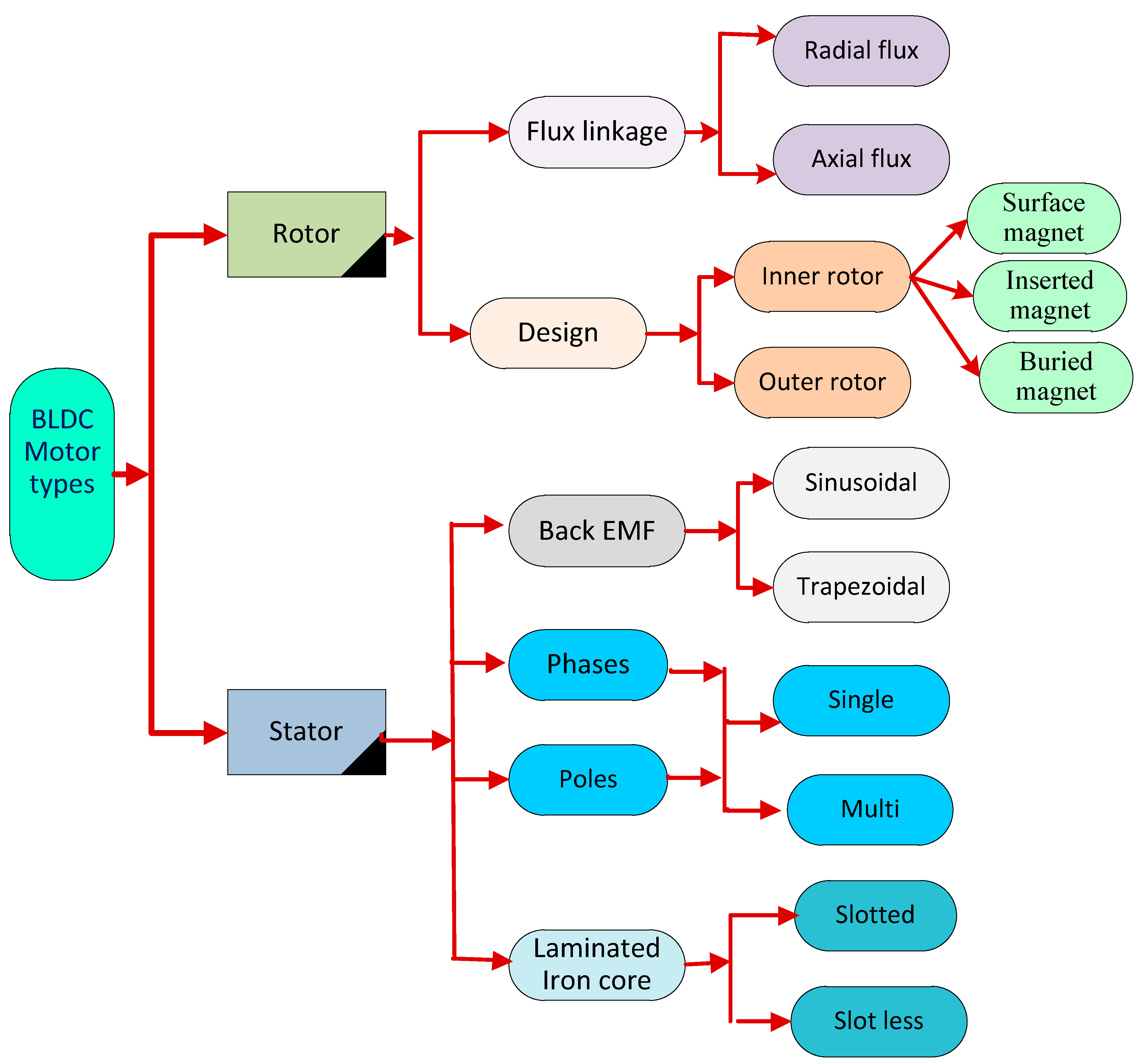
Figure 1. BLDC motor types.
Fractalfract 08 00061 g001
Figure 2. BLDC motor control methods.
Fractalfract 08 00061 g002
Figure 3. Circuit equivalent of three-phase, Y-connected BLDC motor.
Fractalfract 08 00061 g003
Figure 4. Three-phase BLDC motor schematic diagram.
Fractalfract 08 00061 g004
Figure 5. Closed-loop structure of the speed control system.
Fractalfract 08 00061 g005
Figure 6. Speed control with current limitation.
Fractalfract 08 00061 g006
Figure 7. Structure of proposed controller: (a) PID controller structure; (b) FO-PID controller structure; (c) TID controller structure.
Fractalfract 08 00061 g007
Figure 8. The proposed system of the BLDC motor modeled on MATLAB/Simulink.
Fractalfract 08 00061 g008
Figure 9. Simulated waveforms: (a) battery current, (b) battery voltage and (c) battery SOC.
Fractalfract 08 00061 g009
Figure 10. Simulated input power.
Fractalfract 08 00061 g010
Figure 11. Simulated three-phase stator current.
Fractalfract 08 00061 g011
Figure 12. Simulated stator back EMF for phase a, b, c.
Fractalfract 08 00061 g012
Figure 13. Simulated electromagnetic torque and rotor angle (speed mean current).
Fractalfract 08 00061 g013
Figure 14. Simulated driving cycle speed.
Fractalfract 08 00061 g014
Figure 15. Simulated six-switch pulses before using PWM.
Fractalfract 08 00061 g015
Figure 16. Assembly of BLDC motor drive: (a) assembly process; (b) 3-phase inverter.
Fractalfract 08 00061 g016
Figure 17. Experimental setup: (a) using Arduino UNO controller; (b) whole system setup.
Fractalfract 08 00061 g017
Figure 18. Three-phase voltage waveforms at high speed.
Fractalfract 08 00061 g018
Figure 19. Three-phase voltage waveform with graually reducing speed.
Fractalfract 08 00061 g019
Figure 20. Three-phase voltage waveforms at very low speed.
Fractalfract 08 00061 g020
Figure 21. Bode plot of BLDC motor drive.
Fractalfract 08 00061 g021
Figure 22. Pole-zero map method for BLDC motor drive.
Fractalfract 08 00061 g022
Table 1. Using in-wheel motor specifications to compare motors.
FeaturesBLDC
Motor
SR MotorInduction MotorDC Motor
Commutation Electronicelectronic-Brushes
Slip --Applicable-
Efficiency 5332
High-speed rating 5533
Broader steady power speed range 3542
Complexity of control 2235
Torque/speed 5343
A responsive dynamic 5234
Power-to-size ratio 4433
Lifetime 5532
Maintenance requirements 5542
Sensitivity to noise 5233
Fault speed 3542
Torque during a fault 4241
Speed during mechanical shocks 3454
Torque during mechanical shocks 4233
Cost of production 2455
Total 60535444
Table 2. BLDC motor simulation parameters.
DescriptionValue
Number of phases3
Number of poles8
Rated voltage48 VDC
Rated speed3000 RPM
Rated torque0.7 N·m
Rated current6.3 A
Rated power220 W
Peak torque2.1 N·m
Peak current19 A
Back EMF13 V/krpm
Torque constant0.12 N·m/A
Rotor inertia800 g·cm2
Body length84.5 mm
Disclaimer/Publisher’s Note: The statements, opinions and data contained in all publications are solely those of the individual author(s) and contributor(s) and not of MDPI and/or the editor(s). MDPI and/or the editor(s) disclaim responsibility for any injury to people or property resulting from any ideas, methods, instructions or products referred to in the content.