Article

Energy Transfer and Destabilizing Impulse Inducing Mechanism of Coal–Rock System in Roadway through Coal Seam in Deep Zone

1
School of Mining Engineering, Anhui University of Science and Technology, Huainan 232001, China
2
The State Key Laboratory of Coal Resources and Safe Mining, China University of Mining and Technology, Xuzhou 221116, China
3
Shandong Energy Group Luxi Mining Co., Ltd., Heze 274700, China
4
Shandong Energy Northwest Mining Group Zhengtong Coal Company, Xianyang 712000, China
*
Author to whom correspondence should be addressed.
Fractal Fract. 2023, 7(7), 550; https://doi.org/10.3390/fractalfract7070550
Submission received: 4 June 2023 / Revised: 10 July 2023 / Accepted: 13 July 2023 / Published: 16 July 2023
(This article belongs to the Special Issue Fractal Analysis and Its Applications in Rock Engineering)

Abstract

:
Aiming at the problem of the unclear rock burst generation mechanism and anti-impact measures of a large roadway through a coal seam in a deep panel area, taking the rock burst of a large roadway in the first panel area of Gaojiapu Coal Mine as the engineering background, this paper adopts the comprehensive research methods of theoretical analysis, experiments, numerical simulation, fragmentation fractal analysis, and field monitoring, to discuss the mechanical characteristics of the loading process of the assemblage and the energy transfer law and its difference in the deformation and failure process. The possibility and strength of the impact failure of coal under the grip of rock masses with different stiffness are related to the γ value. The smaller the γ value is, the higher the impact possibility is, and the more severe the impact degree is. The assemblage under the grip of soft rock is more prone to system instability. Energy relief and impact reduction are adopted to reduce the post-peak stiffness and elastic strain energy of the coal body in a short distance, avoid the energy transfer and concentration of the roadway surrounding the rock system under the disturbance of a long-distance dynamic load, and reduce the likelihood of impact pressure occurring and the extent to which an impact manifests.

1. Introduction

As coal mining proceeds deeper in China, the mining difficulty is aggravated, and the frequency and intensity of rock burst accidents are obviously escalated. Limited by comprehensive factors, such as fold structure, mining method, and driving speed, developing and preparation roadways, such as main roadways or rise entries or chambers, usually run through different coal seams. Under the sustained high-stress dynamic load disturbance, the rock burst of such roadways can be easily concealed and ignored, without evident macroscopic precursors, making accurate early warning difficult and usually leading to severe losses of life and property. For example, “5.24” in Mengcun Coal Mine, Shandong Province, China; “10.25” in Xinjulong Coal Mine, Shandong Province, China; and “8.15” in Gaojiapu Coal Mine, Shaanxi Province, China, have posed serious impacts on the safety of both mines and personnel [1].
Since Cook put forward the strength theory in 1951, Chinese and foreign scholars have put forward a series of rock burst-related theories. For example, P.P. Prochazka, Dyskin, Zhou R Z, Huang Q X et al. [2,3,4] studied the crack propagation instability and fracture mechanism of rock burst from the perspective of fracture mechanics and crack propagation. Manoj N. Bagde [5] studied the effect of on-site disturbance stress on the dynamic instability of rock formations. Gao M S [6] established a dynamic analysis model of impact source disturbance of roadway surrounding rock, and derived the stress criterion and energy criterion of the dynamic failure of roadways surrounding rock-bearing structures under the combination of “static load + dynamic load”. Studies show that rock burst results from the comprehensive action of force and energy, and the type of external force source and the structure of surrounding rocks of a roadway are closely related to the possibility and intensity of rock burst in deep roadways. Especially for the coal–rock systems that determine the disaster degree of rock burst in roadways, the occurrence of rock bursts is affected by the combination form of coal–rock systems, the transmission of force and energy, and their difference, etc., making it significant to discuss the mechanical properties and energy evolution characteristics of combined coal–rock mass [7,8].
Firstly, in terms of the mechanical characteristics of combined coal and rock mass, rock burst is the result of the discontinuous transmission of force and energy between the roof and floor and the coal seam under the combined action of the primary rock stress and the mining-induced stress, and its occurrence not only depends on the properties of the coal–rock, but also has a close relationship with the combination form of the coal and rock mass, the stress environment, the properties of the surrounding rock, and other factors. It is gradually agreed that the basic experimental research on rock burst using combined coal and rock mass is gradually recognized [9]. Tan Y L [10] proposed and suggested that two impact tendency indexes, the coal–rock combined impact energy velocity index and the unloading pressure impact energy velocity index, be added to the Chinese national standard. Eberhardt [11] applied cyclic load to the coal–rock specimen to obtain the brittle fracture mechanical properties of the coal and rock mass, and proposed the fracture criterion. Liu S H [12] analyzed the propagation and energy dissipation mechanism of stress waves in combined coal–rock under dynamic and static loading and constructed a mutation model of the dynamic instability of combined coal and rock mass. Liu B [13] carried out a conventional uniaxial compression test using the height of the coal–rock combination as the research variable, and the results showed that with the increase in the proportion of rock mass height in the combined sample, the dynamic failure time gradually decreased, and the impact tendency gradually increased. Tutuncu [14] carried out cyclic loading and unloading tests on sedimentary rocks and found that the loading rate and strain amplitude had great influences on the mechanical properties of sedimentary rocks. Zhao X Y [15] conducted uniaxial compression tests on the samples of “coal-rock” and “rock-coal-rock” combinations, and found that the existence of rock mass made the instability process of the coal–rock composite specimen more and more abrupt, and the precursor information was difficult to identify. Zhao S K [16] carried out uniaxial compression numerical simulation tests on coal–rock composite specimens with different coal–rock height ratios and contact surface angles; the results showed that with the gradual enhancement of rock hardness, the impact tendency of the combined specimens was gradually strengthened, and with the gradual increase in the angle of the coal–rock contact surface, the uniaxial compressive strength of the coal–rock composite specimens gradually weakened. Liu J [17], through the uniaxial compression test of pure coal, pure rock, and coal–rock combination specimens, found that the total stress–strain curve of the coal–rock combination is located in the middle position of the full stress–strain curve of pure coal and pure rock specimens and is relatively close to the coal body.
In terms of energy evolution, “impact pressure is a nonlinear dynamic process of steady state accumulation of energy and unstable release of energy during the deformation and failure of coal–rock mass caused by mining activities”, which is a generally accepted viewpoint, and establishing a dynamic instability model and discriminant criterion for surrounding rocks in roadways from the perspective of energy mutation is an effective way to explore the mechanism of impact pressure disaster [18]. For example, the energy accumulation and transfer law during the rock burst is studied by establishing the instability energy model of coal–rock mass; or revealing the mechanism of its occurrence from the perspective of energy for a certain type of rock burst; or obtaining the failure type, mechanical properties, acoustic emission, charge time–frequency domain signal, fragmentation fractal characteristics, etc. of the loading and unloading combined coal and rock mass. For example, He MC Dynasty [19] designed and developed the impact rock burst test system, combined it with the image acquisition system, obtained the whole process of sandstone impact rock burst, and provided the relationship among dynamic stress, energy, and induced rock burst under the condition of sine wave form disturbance loading. Dou L M [20] put forward the principle of dynamic and static load superposition-induced rock burst, revealed the mechanism of rock burst from the energy perspective, studied the unstable energy trigger mechanism of impact ground pressure through theoretical analysis and the spatiotemporal intrinsic relationship between on-site measured microseism activity and rock burst, obtained the energy trigger conditions of dynamic catastrophe, and put forward the prediction and prevention ideas of rock burst. Lau and Chandler [21] point out that the unloading test method can obtain rock mechanical parameters more accurately than the loading test method. Since the mechanical parameters and deformation parameters of rocks under most engineering unloading paths show deterioration characteristics, it is no longer a linear change law under conventional stress conditions. The rock mechanics and deformation characteristic parameters derived from the unloading theory are more in line with the actual situation, which can provide more favorable theoretical support for practical engineering [22,23,24]. Zhang Z Z and Gao F [25,26] studied the influence of water content and lithology on rock energy evolution through uniaxial cyclic loading and unloading experiments, and pointed out that the saturation process of rock reduces the energy absorption limit of rock and promotes rock energy dissipation behavior, which was further verified by Niu et al. [27]. In summary, in terms of the coal–rock complex, a large number of microseism data and the stress wave theory of coal mine impact ground pressure accident site are synthesized, and it is found that the dynamic load strain rate caused by mining activities in coal mines ranges from 10−3 s−1 to 10−1 s−1, which belongs to the low-medium strain rate, and the mechanical characteristics of coal–rock mass under the action of a low-medium strain rate dynamic and static load are relatively insufficient. In particular, the whole process of combined coal–rock mass failure of “single face unloading-five-sided static load-vertical application of medium strain rate dynamic disturbance” that is closer to the stress path transformation and boundary condition change before and after roadway excavation and during the remining process is rarely reported. In terms of energy, the previous laboratory tests did not refine the combination of external force sources and roadway surrounding rock structure, and less consideration was given to the transformation of stress conditions and boundary conditions during roadway excavation and coal mining face remining, which was far from the real state and mining process of the surrounding rock geological environment of the deep roadway, and it was necessary to carry out more in-depth and detailed research on the basis of previous research results. On the basis of the above research, this paper takes Gaojiapu Panel 1 of Shaanxi Province, China, as the engineering background; summarizes the external force source types and the surrounding rock structure forms of the rock burst; simplifies the transformation of the stress path and the change of boundary conditions before and after the excavation of the roadway; and uses the true triaxial mechanical test system to carry out the typical combined coal–rock mass under different stress paths (small cyclic disturbance in the axial direction of unloading pressure and axial slope disturbance of unloading pressure) on the basis of conventional mechanical tests, the medium strain rate dynamic, and static combination plus the unloading test, combined with numerical simulation, and comprehensive field monitoring based on the distribution features and impact location of mine earthquakes in the main roadway in this panel area. This study aimed to explore the maximum principal stress and elastic strain energy distribution of such combinations under different stiffness values, discuss the damage degree of coal clamped by roofs and floors with different stiffness values, and establish a force–energy interaction model of the coal–rock system, and the study results provide a certain reference for exploring the occurrence mechanism and prevention and control technology of rock bursts in the main roadway of deep panel areas.

2. Appearance Characteristics of Rock Burst in the Main Roadway of a Deep Panel Area

Gaojiapu Coal Mine is located in the northwestern part of the Binchang mining area in Shaanxi Province, China; it is the second pair of modern large-scale mines developed and constructed by Shandong Energy Zikuang Group in the Binchang mining area, Shaanxi Province. The main level of Gaojiapu Coal Mine is located in the 4# coal seam, and the occurrence depth is 800–1000 m. The coal seam has a strong impact tendency, and the roof and floor strata are mudstone with a weak impact tendency. The buried depth of three main roadways in Panel 1 is about 800 m, most of which is arranged along the coal seam. Among them, the belt roadway is a coal roadway, and the return airway and auxiliary haulage roadway are partly coal roadways and rock roadways. The specific distribution of the main roadways in the panel is shown in Figure 1. Affected by the structural layout, areas crossing the coal seal appear in some roadways during mining and advancement, and roadway surrounding rocks change dramatically.
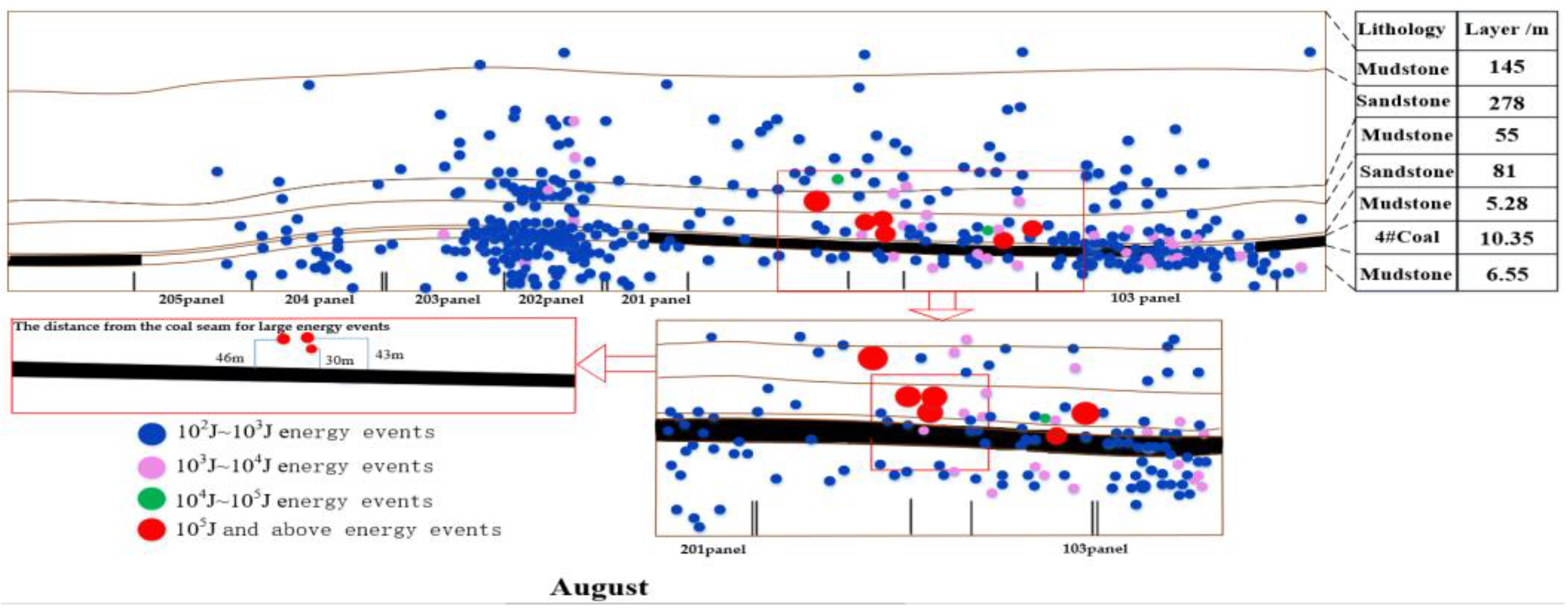
In the stoping process, many major energy events 105 J or above occurred in the coal mass roadway in Panel 1 of Gaojiapu, and the impact appeared. Taking the typical impact phenomenon in August 2018 as an example, the impact phenomenon appeared on the 16th day of that month, and the on-site impact and microseisms in August are shown in Figure 2. In the process of the impact appearance, the impact position of the roadways was basically located in the area where the roadways in Panel 1 passed through the coal seam. The impact appearance degree was the highest in the return airways, followed by the belt roadways, accompanied by head-on impact, rapid heaving of the roadway floor, and sudden bulging of the two sides. Combining the field microseismic monitoring situation, it was found that before and after the impact, the energy in the corresponding area experienced a change in the magnitude from 105 J to 104 J. The focal points of the 105 J events monitored by the microseismic system were in the coal pillar of the main roadway and the adjacent roof strata, and the impact type was speculated to be coal outburst type rock burst.
It could be seen that when the impact occurred in the main roadway of Panel 1, a total of five major energy events were monitored in its nearby areas, in all of which the coal seam was traversed. In addition, the impact locations and earthquake source locations were basically the same, but the high-energy events 105 J or above near the main roadway in rock strata did not cause the impact appearance, and no impact was triggered at locations with a high frequency of microseismic energy, but the main roadway in the panel area was impacted at locations with a low frequency of microseismic energy. It could be discovered that major energy events might not be completely identical with the roadway impact in the aspect of location, and not all major energy events would trigger the impact.

3. Force and Energy Response Characteristics of Coal and Rock Systems with Different Stiffness Values

3.1. Test Method

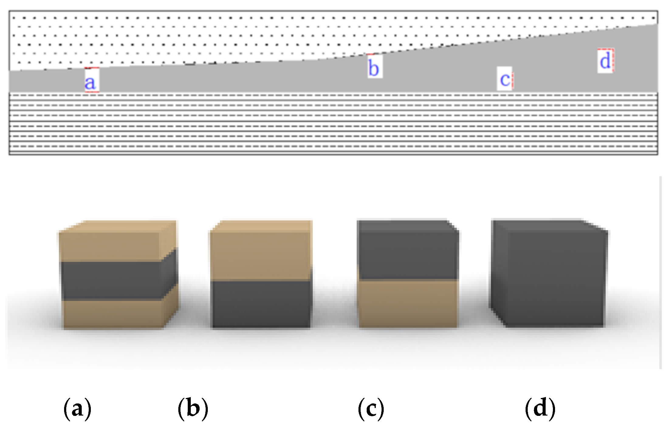
Given the position of the Panel 1 main roadway in the coal seam, the surrounding rock structure of the roadway was simplified into a pure coal structure and a rock–coal–rock composite structure (the simplified models shown in Figure 3 are rock–coal–rock (Figure 3a), rock–coal (Figure 3b), coal–rock (Figure 3c), and coal (Figure 3d)). To explore the failure mechanism of the coal mass under rock masses with different stiffness values, several intact large coal and rock blocks were taken from Gaojiapu Coal Mine and processed into cubic specimens with dimensions (height × length × width) of:
(1)
Coal: 100 mm × 75 mm × 75 mm;
(2)
Sandstone–coal–Sandstone: Sandstone 30 mm × 75 mm × 75 mm, Coal 40 mm × 75 mm × 75 mm, Sandstone 30 mm × 75 mm × 75 mm;
(3)
Mudstone–coal–Mudstone: Mudstone 30 mm × 75 mm × 75 mm, Coal 40 mm × 75 mm × 75 mm, Mudstone 30 mm × 75 mm × 75 mm.
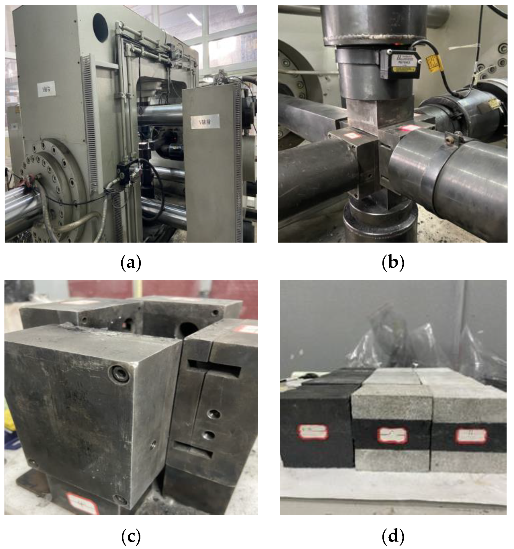
As shown in Figure 4, pure coal and coal–rock combinations were subjected to mechanical tests using the dynamic impact appearance test system of mined coal and rock mass from China University of Mining and Technology, and the stress–strain conditions and impact appearance of three groups of specimens were recorded.
In the past, the equipment for the mechanical characteristics of the previous combined coal mass was mainly MTS and RMT. The loading method of this equipment is quasi-static, which is a low strain rate loading method, or the experiment of using a high strain rate Hopkinson rod. However, a large number of microseism data and stress wave theory at the site of the coal mine impact pressure accident are analyzed, and the dynamic load strain rate caused by mining activities in the coal mine ranges from 10−3 s−1 to 10−1 s−1, which belongs to the low-medium strain rate.Table 1 shows the on-site mineral seismic energy, strain rate and other data collected by Dou Linming’s research group. Therefore, the previous experiments’ results cannot reflect the real condition in the site, and the mechanical characteristics of coal–rock mass under the action of the low-medium strain rate dynamic and static load are relatively insufficient, especially closer to the stress path transformation and boundary condition change before and after roadway excavation and during the recovery process. “The whole process of the failure of the combined coal–rock mass with a single face unloading-five-sided static load-vertical application of medium strain rate dynamic disturbance” is rarely reported.
In response to the above problems, our research group independently developed a true three-axis mining coal–rock dynamic display test system with independent property rights, which can realize the strain rate dynamic disturbance in the typical combined coal–rock mass under complex stress paths. According to the static stress characteristics of the surrounding rock applied to the roadway and the type of dynamic load stress wave, the stress conditions are simplified into two kinds of dynamic and static combined loading stress paths: small cyclic disturbance in the axial direction of unloading pressure and axial slope disturbance of unloading pressure.
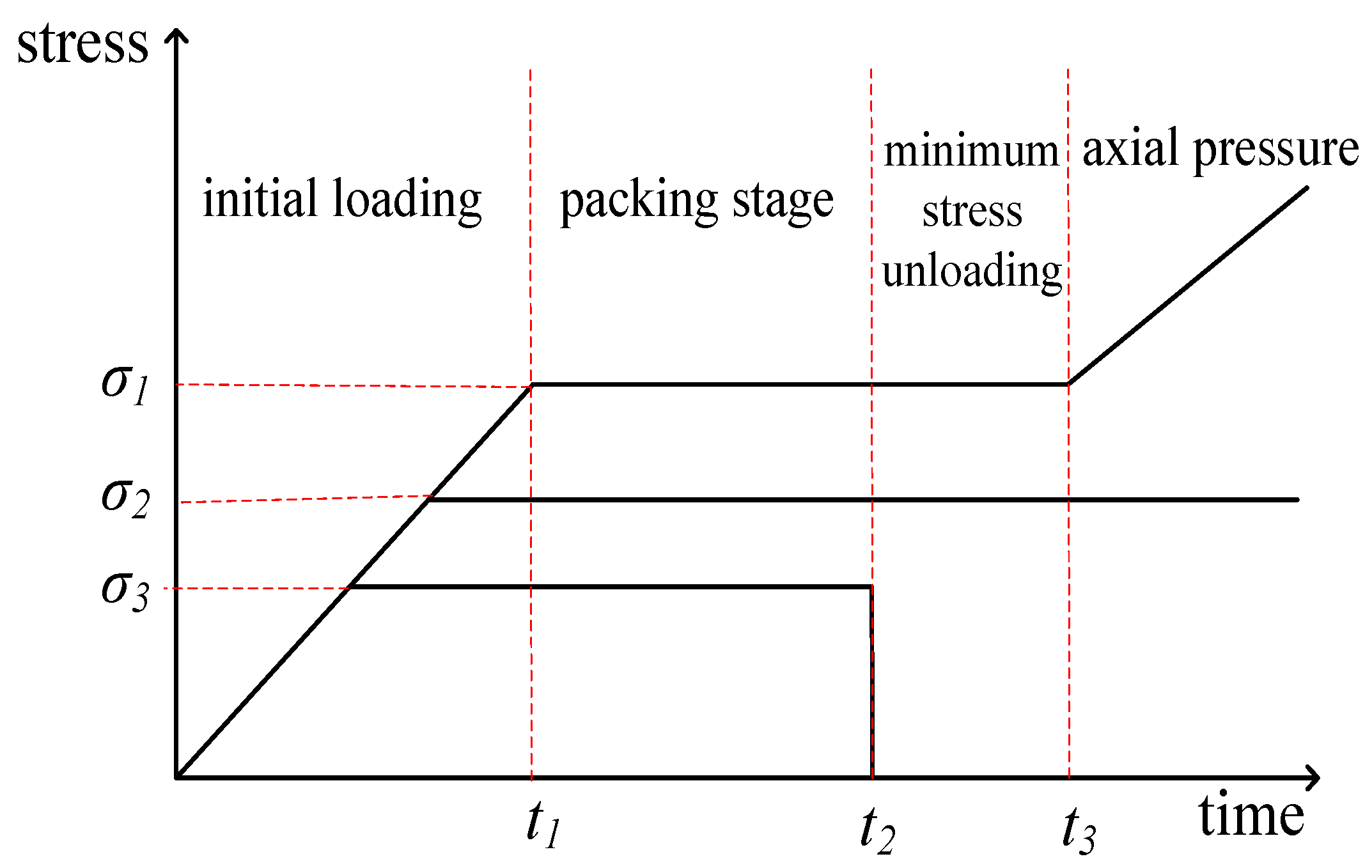
The mechanical test was performed by unloading the minimum principal stress σ3, keeping the intermediate principal stress σ2 unchanged and changing the maximum principal stress σ1. Considering the roadway excavation in real environments, the impact of roadway excavation was simulated by suddenly unloading the minimum principal stress σ3. The stress loading paths of different coal–rock combinations under static load conditions are shown in Figure 5, and the test stages are as follows:
(1)
Initial stress loading stage: Three kinds of composite structures were each loaded to the initial stress environment with σ1 = 10 MPa, σ2 = 6 MPa, σ3 = 5 MPa, and loading rate = 0.05 MPa/s.
(2)
Pressure maintaining stage: With the three-way stress bearing of the specimen unchanged by means of force control, loading was performed for 120 s under pressure maintaining conditions, so as to reach the initial stress environment conforming to the field situation.
(3)
Minimum principal stress unloading stage: Instantaneous unloading was conducted at one side of the minimum principal stress σ3 to simulate the real situation in the case of sudden stress unloading at the side of the roadway excavation, and the maximum principal stress σ1 and intermediate principal stress σ2 were continuously kept constant by means of force control for 45 s.
(4)
Axial compression stage: The intermediate principal stress σ2 was unchanged, and the maximum principal stress σ1 was increased at a loading rate of 0.5 MPa/s until specimen failure.

3.2. Test Phenomena

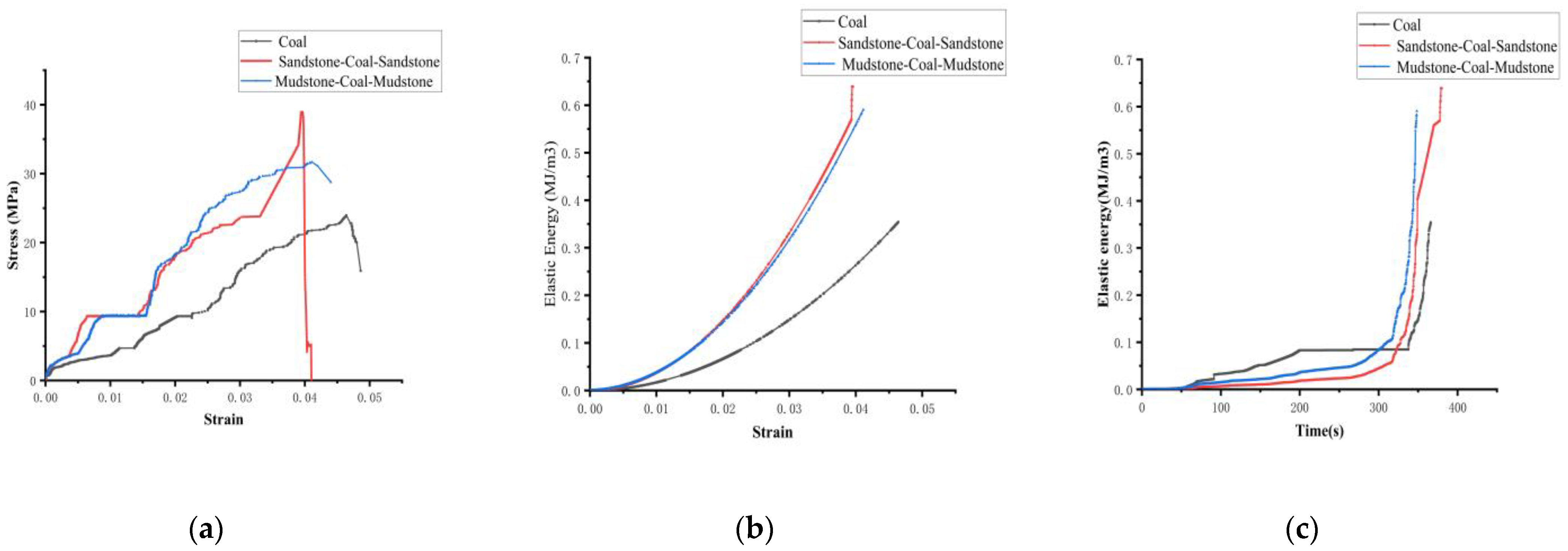
The characteristic parameters of different coal–rock combinations in the loading process are shown in Table 2, the force–energy correlation curve is shown in Figure 6, and the failure impact appearance process is exhibited in Figure 7. In the initial stress loading stage, the strains of the three composite structures all increased gradually with the increase in stress, and meanwhile, they absorbed energy from the outside, and the curves basically increased linearly. In this case, they mainly accumulated in the coal and rock mass itself in the form of elastic strain energy. After entering the pressure holding stage, the stress, strain, and absorbed energy tended to be stable. The three groups of specimens entered the axial compression stage after pressure maintaining for 338.11 s, 321.52 s, and 303.99 s, the curves changed from gentle to steep, and the absorbed elastic strain energy gradually increased. The incubation time for loading to the peak point and dynamic failure time were relatively long when the coal mass was clamped by large-stiffness sandstone; the failure strength and the generated elastic strain energy were large, while the generated strain was relatively small.
In the pure coal structure, the coal mass began to be split into blocks and plates at 367.01 s, accompanied by a crisp sound in the process of failure. At 368.92 s, the coal mass was splashed out in blocks, while at 370.72 s, a large amount of coal debris gushed out when it was sprayed, and at 371.81 s, the surface of the damaged coal mass was uneven with many micro-cracks. This was because there were many pores in the coal mass during loading. Under the action of external forces, the cracks inside the coal mass propagated rapidly, and as a result, the overall coal mass mainly presented an “X”-shaped fracture after failure.
In the sandstone–coal–sandstone combination, the coal mass was subjected to granular ejection, along with cracks at 376.52 s, oblique cracks appeared in the roof sandstone, and the floor sandstone showed no visible changes. In this case, the failure strength of the coal–rock mass was not reached yet. When loaded to 384.52 s, the coal mass was mostly ejected out in the form blocks, a large amount of coal dust gushed out at 386.63 s, and the failure ended at 388.02 s. Finally, the floor was not damaged, and the roof split into blocks, with a lot of coal debris generated.
In the mudstone–coal–mudstone combination, the seam between the coal mass and the floor mudstone peeled off in particles at 348.17 s, and the floor obviously cracked, and the roof had no visible changes. At 350.78 s, a large number of coal bodies gushed out, and the floor mudstone split in blocks, and the coal mass was severely damaged at 352.58 s, and the floor splashed out with coal. After 5 s of coal mass damage, the roof strata were severely damaged, and the failure ended at 358.08 s. The whole coal–rock combination was violently damaged, accompanied by lots of coal and rock fragments.
The following relationships could be obtained accordingly:
(1)
Failure strength: sandstone–coal–sandstone combination > mudstone–coal–mudstone combination > pure coal;
(2)
Strain at peak point: pure coal > mudstone–coal–mudstone combination > sandstone–coal–sandstone combination;
(3)
Energy at peak point: sandstone–coal–sandstone combination > mudstone–coal–mudstone combination > pure coal;
(4)
Incubation time of failure: sandstone–coal–sandstone combination > mudstone–coal–mudstone combination > pure coal;
(5)
Dynamic failure time after peak: sandstone–coal–sandstone combination > mudstone–coal–mudstone combination > pure coal.
By comparing the mechanical test phenomena and the appearance process of the impact failure of coal, “sandstone-coal-sandstone”, and “mudstone-coal-mudstone”, it could be found that the appearance process of the impact failure of coal and rock mass could be divided into typical stages, such as particle ejection, splitting into blocks, block ejection, and debris emission. Pure coal showed the overall push-out impact, the sandstone–coal–sandstone combination was dominated by the extrusion instability of the clamped coal specimen, and the mudstone–coal–mudstone combination was mainly subjected to the splitting failure of the coal specimen and the floor mudstone. The failure of the coal–rock system mainly depended on its own maximum principal stress and elastic strain energy. The coal–rock mass started to accumulate energy from a stable equilibrium state, and it was stored in itself through elastic deformation of the coal–rock system. When the energy of the coal–rock system accumulated too much, the system would change and become unstable, and many micro-cracks and cracks penetrated each other, and then developed into macro-cracks. When the local stress concentration exceeded the local strength, particles and fragments were thrown, and the range and quantity of particles and fragments increased on the basis of increasing stress. When the ultimate strength of coal and rock mass was reached, the internal energy storage was released quickly, which led to the violent ejection of coal blocks at and near the free surface, making a loud noise. Meanwhile, it could be seen that the damage degree of the coal mass was relatively more severe under the clamping of mudstone, which was ascribed to the low rigidity of mudstone and the easy accumulation of energy. Therefore, all the energy released by mudstone could not be consumed by the intermediate coal mass, which resulted in the instability and failure of the coal mass under the clamping of mudstone.
To sum up, from the combination form of coal and rock, due to the participation of the roof, the coal–rock combination was characterized by higher bearing capacity, higher accumulated energy before impact, and longer impact time than pure coal specimens. From the different stiffness conditions, sandstone exhibited higher stiffness than mudstone, so it exerted a higher influencing degree on the impact. The instability form and impact form of the coal–rock combination were more complicated than those of pure coal, and the law of force and energy transfer was more complicated.

4. Evolution Law of Stress–Energy Field of Different Coal and Rock Systems

4.1. Establishment of Numerical Model

Through the mechanical tests of different coal–rock combinations in the previous section, it was found that the maximum principal stress and elastic strain energy played a leading role in the failure of the coal–rock mass during the loading process. Therefore, numerical calculation parameters of the coal–rock mass were established based on laboratory test data, and the evolution law of maximum principal stress and elastic strain energy during the loading process was studied in detail, and the failure mechanism of the coal–rock mass was further analyzed. Next, the theoretical analysis and test results were verified to explore the distribution of maximum principal stress and elastic strain energy under different stiffness values of the combinations and discuss the failure degree of the coal mass under the clamping action of roofs and floors with different stiffness.
According to the different stiffness values of the roof and floor, three different coal–rock combination systems were designed: pure coal, sandstone–coal–sandstone, and mudstone–coal–mudstone. Three numerical models were established with FLAC3D 5.0 simulation software, which were divided into 21,925 grids, and axial pressure was applied at the rate of 0.05 MPa/s The specimen was divided into three regions, I, II and III, in which region II was clamped by region I and III, and region II was given the parameters of coal mass, while regions I and III were given the parameters of coal mass, sandstone, and mudstone. The stress value and elastic strain energy of region II and the whole coal–rock system were automatically recorded by the FISH language. On the premise of sandstone strength > mudstone strength > coal strength, the stress characteristics and energy of coal mass clamped by rocks differing in stiffness were comparatively analyzed. The physical and mechanical parameters of coal-rock mass are shown in Table 3.

4.2. Evolution Law of Force and Energy in Loading Process

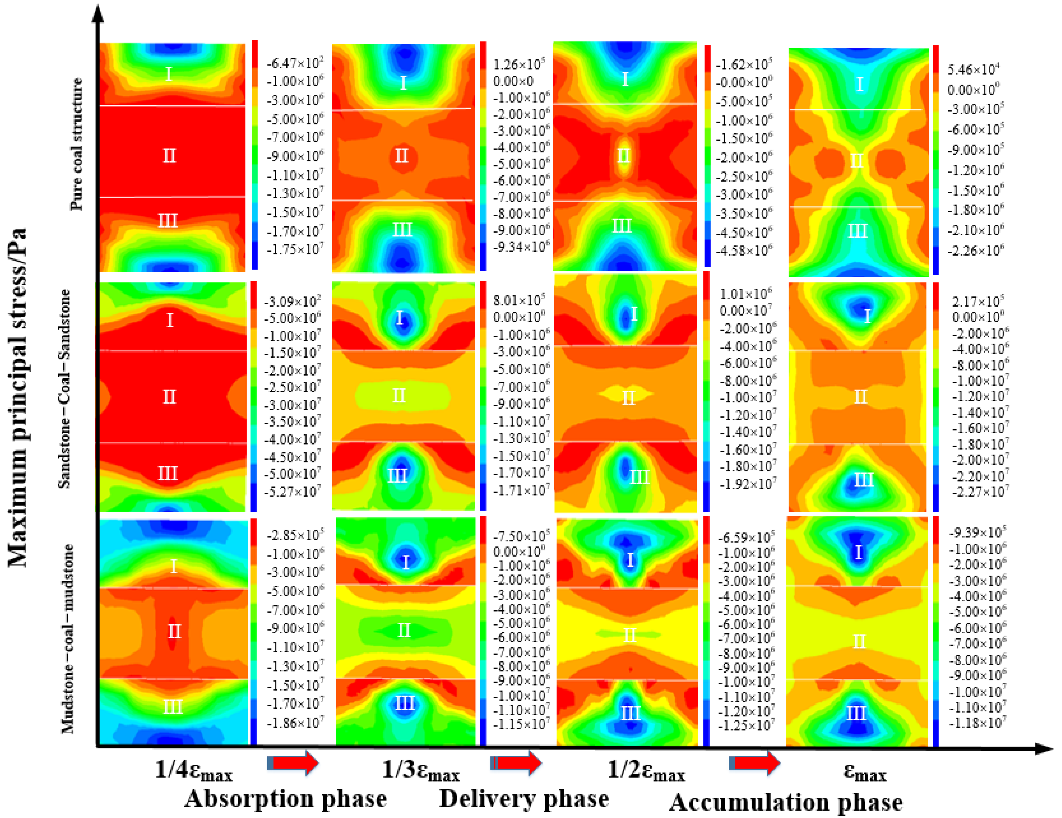
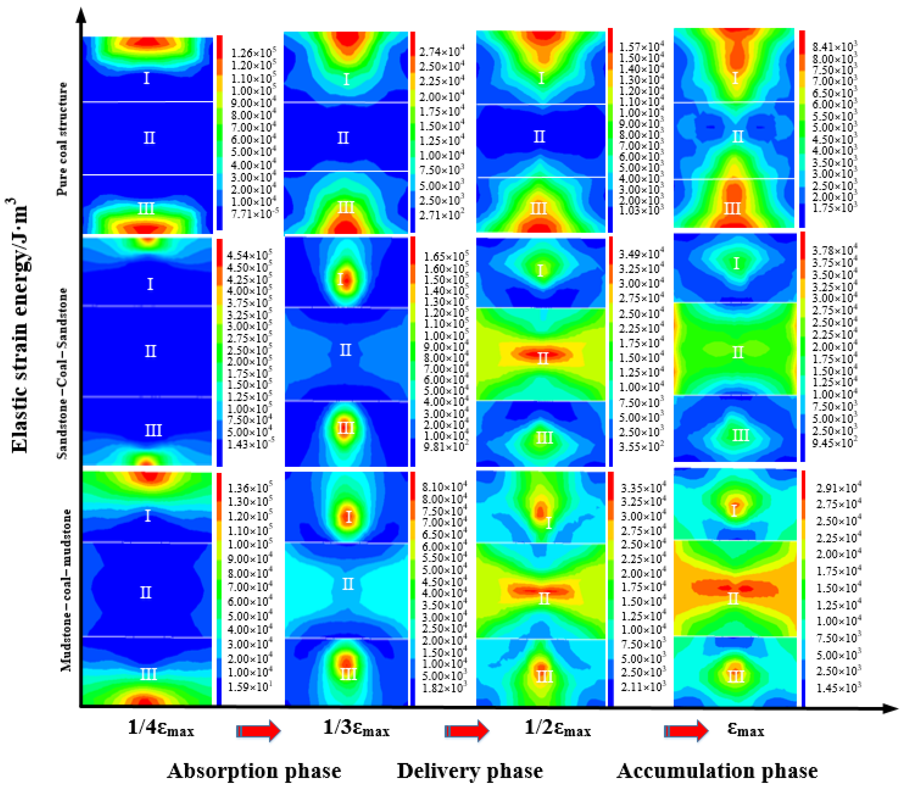
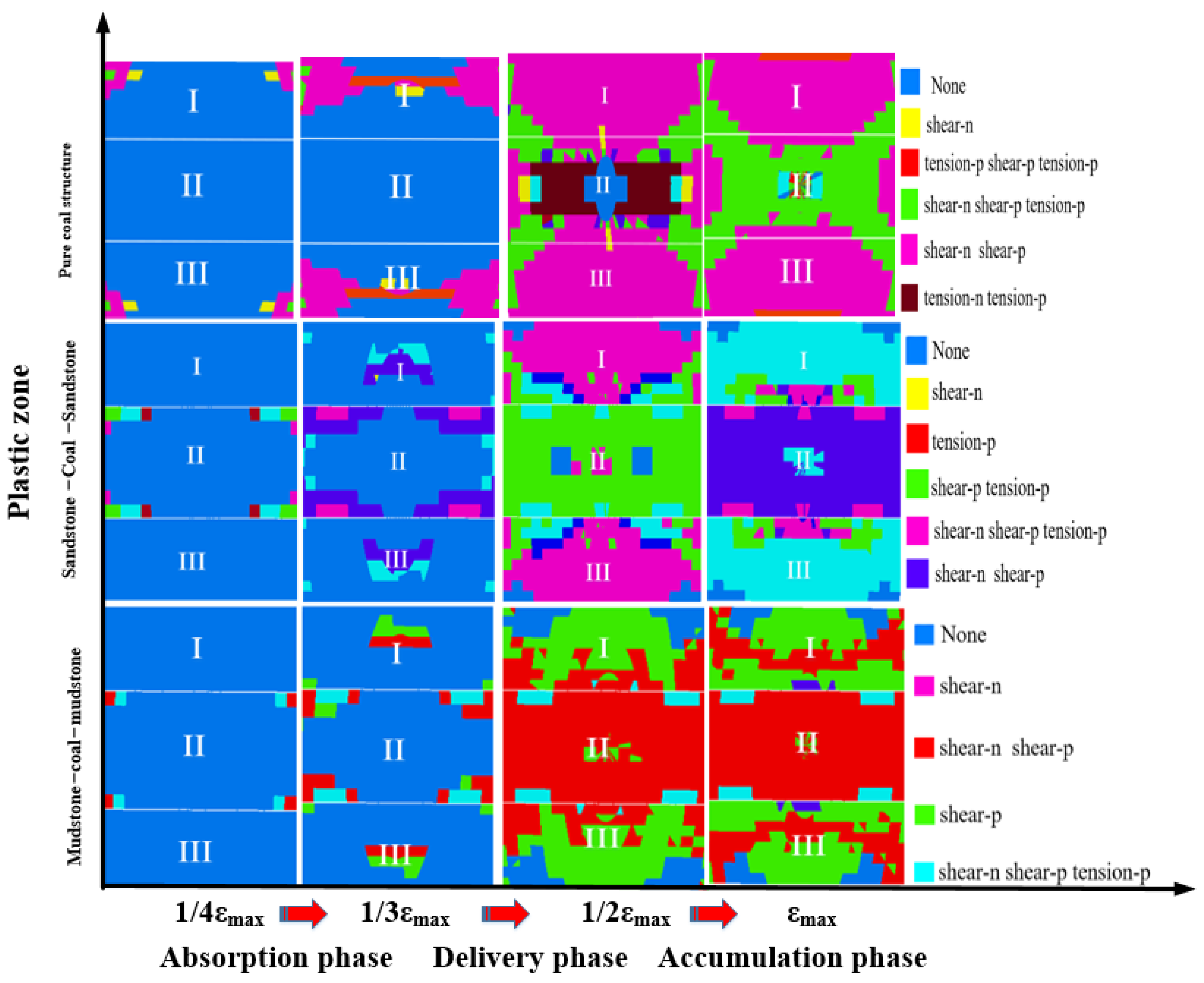
The evolution laws of the maximum principal stress, elastic strain energy, and plastic zone n of the three coal and rock systems in the previous section are shown in Figure 8, Figure 9 and Figure 10, in which region II was all coal. The force and energy characteristic parameters of local coal masses in three stages of the three coal–rock systems are shown in Table 4. The maximum principal stress and elastic strain energy of the three coal–rock systems increased at first and then decreased, and their evolution could be roughly divided into three stages: absorption–accumulation–release.
(1) Absorption stage: In the pure coal structure, the displacement at the end edge of the coal mass was relatively large, with an obvious stress concentration phenomenon. The top and bottom of the coal mass were greatly affected by the maximum principal stress, that is, the relative displacement dislocation of region I and region III occurred along the radial force direction, and the trend of shear deformation was generated. Region II gradually absorbed the maximum principal stress and elastic strain energy transmitted by regions I and III. In the sandstone–coal–sandstone structure, the maximum principal stress gradually increased, sandstone absorbed elastic strain energy from the outside, and coal gradually absorbed the maximum principal stress and elastic strain energy transmitted from sandstone. At this time, the slight shear deformation in the coal–rock system gradually expanded to sandstone, leading to cracks. In the mudstone–coal–mudstone structure, the coal mass was less affected by the maximum principal stress, and the absorption process at this stage could be roughly simplified as “outside → mudstone → coal mass”.
(2) Accumulation stage: In the pure coal structure, the maximum principal stress in regions I and III was expanded externally, the elastic strain energy accumulated at the top and bottom was gradually transferred to the coal mass in region II, the maximum principal stress and elastic strain energy of the coal mass gradually evolved into a “butterfly” with axial symmetry, and the plastic deformation region of the whole system further expanded from regions I and III to region II. In the sandstone–coal–sandstone structure, the maximum principal stress and elastic strain energy in sandstone were transferred to the coal mass, and the ranges of the high stress area and high energy area in the coal–rock system were gradually expanded, gradually generating the coal mass-centered stress concentration and energy concentration. In the mudstone–coal–mudstone structure, the maximum principal stress and elastic strain energy in mudstone changed into a “V” shape and were transmitted to coal and other positions; at this time, the force energy of the coal–rock system was mainly accumulated in the center of the coal mass.
(3) Release stage: In the pure coal structure, the maximum principal stress and elastic strain energy in the center of the coal mass in region II gradually decreased, and the coal–rock system reached the energy storage limit, which resulted in the release of the elastic strain energy of the coal mass in a butterfly shape and an “X”-shaped shear failure of the whole pure coal system. In the sandstone–coal–sandstone structure, the accumulated large principal stress and elastic strain energy were released and dispersed to all parts of the coal–rock system, and the coal–rock system was damaged. The elastic strain energy released by the coal acted on sandstone, thus damaging it. In the mudstone–coal–mudstone structure, shear fracture occurred in the coal–rock system, and the whole coal–rock system extended from the initial shear deformation of coal to the deformation and failure of mudstone; especially the coal mass experienced large-area shear fracture.
Given the same composition of the pure coal structure and its overall small stiffness, the elastic strain energy could be easily stored in the coal mass and released in itself. As far as the intermediate coal mass was concerned, driven by the maximum principal stress and elastic strain energy, the coal mass had an obvious deformation trend before failure, and finally the coal mass finally presented an “X-shaped” shear fracture with the loading time. When the coal mass was clamped by sandstone with strong stiffness, the deformation amplitude of sandstone was low, and the change of its maximum principal stress caused elastic strain energy to be transferred to the coal mass, forming a stress concentration area centered on the coal mass. Sandstone became the “medium” for the external environment to transfer elastic strain energy to the coal mass, and finally, the elastic strain energy was slowly released by the coal mass, which resulted in the tendency of the coal mass to a shear failure. Compared with hard sandstone, the elastic strain energy of coal was more likely to accumulate in the soft mudstone at the top and bottom. When accumulated to a certain extent, energy would be transferred and released to the coal medium. Because of the change in the maximum principal stress of soft rock, the elastic strain energy released could not be consumed by the coal, and the maximum principal stress inside the coal reached the bearing limit of the coal, resulting in the damage of coal.

4.3. Discussion on the Relationship between Force and Energy of Different Coal and Rock Systems

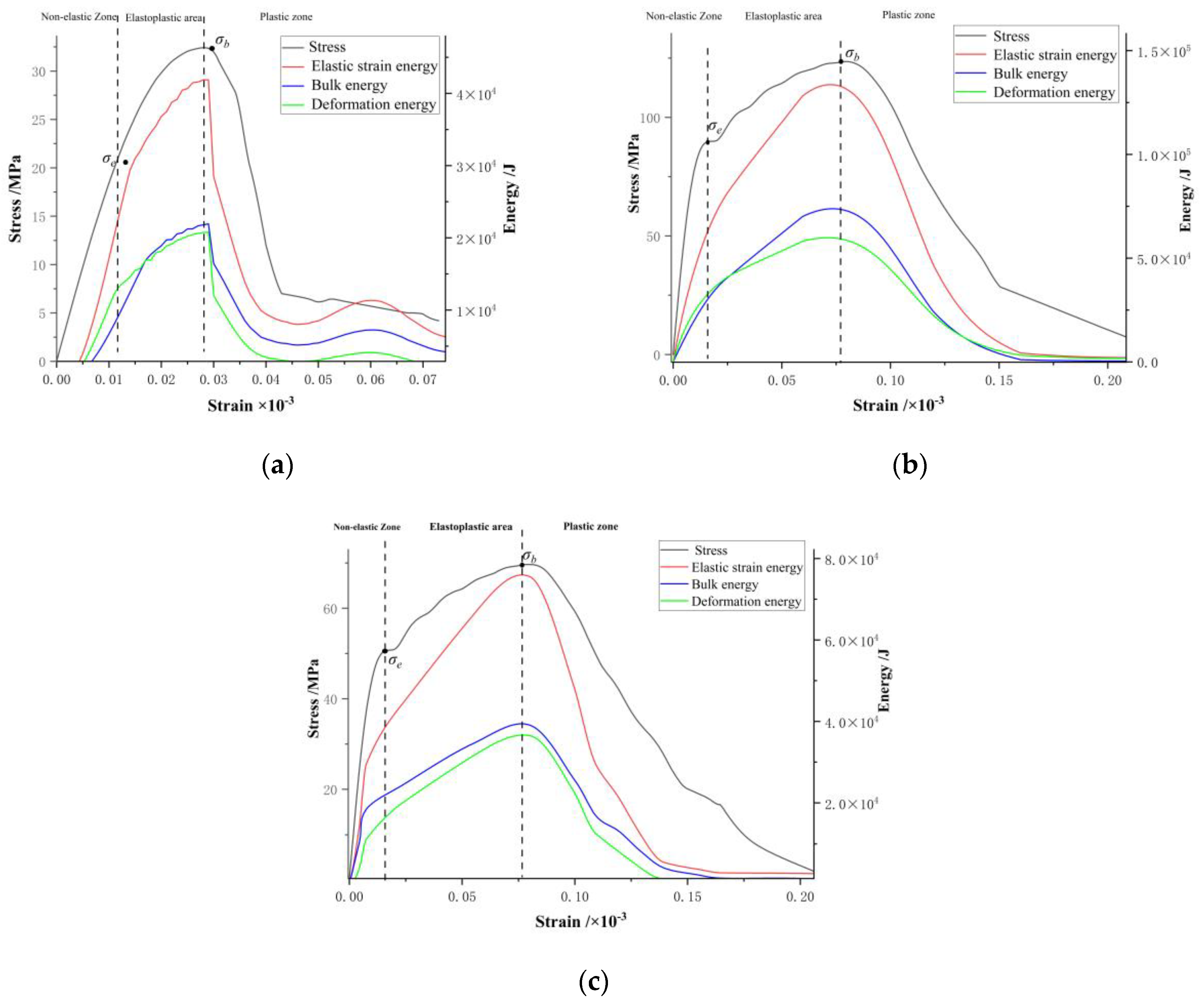
The numerical parameters of the pre-peak force and energy of three coal and rock systems with strain are shown in Table 5, and the evolution process is shown in Figure 11, in which the elastic zone was before the elastic limit σe, the elastic–plastic zone was between σe and the strength limit σb, and the plastic zone was after σb. The evolution trend of stress with strain of the three coal–rock systems resembled that of elastic strain energy. In the elastic zone, the elastic strain energy of the three coal–rock systems showed a gradual upward trend with the increase in stress. When the coal–rock system reached the strength limit, the elastic strain energy reached the maximum value and then showed a gradual downward trend.
From Table 5, it could be seen that the bearing strength and accumulated elastic strain energy of the combined specimen were higher than that of the coal monomer, indicating that the strength and energy evolution trend of the coal–rock combined system was not only related to the properties of coal, but also to the overall function of the combined system. Through the proportional relationship between elastic strain energy and strain, it was concluded that the accumulation rate of elastic strain energy before peak and the release rate of elastic strain energy after peak in the pure coal system were less than those in the two combined systems. In contrast, the deformation of the pure coal system was small, most of the elastic strain energy was not completely released in the coal mass, and the release rate of elastic strain energy after peak in the sandstone–coal–sandstone system with greater stiffness was greater than that in the mudstone–coal–mudstone system with less stiffness. In other words, the release rate of elastic strain energy of the “sandstone-coal-sandstone” system reached 98.69% at the post-peak stage, and that of the “mudstone-coal-mudstone” system reached 95.26% at the post-peak stage, indicating that the elastic strain energy of the coal–rock system with less stiffness accumulated in the coal–rock itself, and thus, the main body of energy accumulation in the coal–rock system was soft rock with less stiffness.
During the loading process, the curve fitting parameters of different coal and rock systems are shown in Table 6, in which the pre-peak linear equation of different coal and rock systems is represented by yi = kixi + bi, and the post-peak linear equation is represented by yi′ = fi′(ui,t) xi + bi′, where bi and ki are the intercept and slope before the peak, respectively, and bi′ and fi′(ui,t) stand for the intercept and slope after the peak, respectively. The stress–strain curves before the peak of different coal and rock systems are shown in Figure 12a, and the total stress–strain curves of coal under different coal and rock systems are shown in Figure 12b.
In order to study the influence of different systems on coal impact, the steady-state index γ in the case of coal failure was defined, so that γi = ki + fi′(ui,t). According to Table 6, the pre-peak slope of the sandstone–coal–sandstone system was much larger than that of the mudstone–coal–mudstone system, and the post-peak slope was much smaller than that of the mudstone–coal–mudstone system, that is, k2 > k3, f2(u1,t) < f′3(u2,t), so the steady-state index γi of the coal mass was obtained:
γ 1 = k 1 + f 1 u 1 , t = 1140.1 ± 60.01 γ 2 = k 2 + f 2 u 2 , t = 170.02 ± 77.7 γ 3 = k 3 + f 3 u 3 , t = 78.48 ± 47.22
It could be seen that the steady-state index γi of coal was larger when being clamped by sandstone with great stiffness, and the index was small when the coal mass was clamped by mudstone with small stiffness. When the coal–rock system was subjected to external forces, the damage of the coal mass clamped by sandstone was more stable. This is because hard sandstone stored less elastic strain energy, which mainly clamped the coal mass. In the process of coal mass damage, most of the energy transmitted by the hard rock body was consumed, and most of the absorbed energy was quickly lost by itself before the failure. Because the stiffness of the coal mass was smaller than that of sandstone, the remaining energy was dissipated by sandstone before being transmitted to the coal mass. However, under the clamping of mudstone, due to the low stiffness of mudstone, elastic strain energy could be accumulated more easily, and most of the elastic strain energy was accumulated in the system before the failure, and it could not be consumed by coal after being released, making it relatively inclined to instability and failure, namely, a smaller γ value indicated the more serious impact degree.

5. Fractal Characteristics of Coal–Rock Samples

5.1. Fractal Dimension Fundamentals

In the mid-1970s of last century, the famous French scholar Mandelbrot [28] proposed the theory of fractal geometry, using fractal dimensions to describe the self-similarity characteristics between parts and the whole of fractal geometry, which opened a new chapter in geometry. Dimensionality is an important parameter that characterizes the state of space, and in Euclidean geometric spaces, dimensionality is usually one, two, or three. At the beginning of the last century, German mathematician F. Hausdorff proposed the concept of fractional dimension from the perspective of sets, breaking through the traditional concept of integer dimension, and using Hausdorff dimension to represent non-integer dimension. Mandelbrot [29] established a fractal model in two-dimensional space through the study of bulk particles in nature. Based on Mandelbrot’s research, Tyler [30] further generalized the fractal model in two-dimensional space to three-dimensional space, and proposed a mass-particle-size fractal model based on the assumption of the same particle density. Since then, experts and scholars at home and abroad have carried out a lot of research on fractal geometry, and applied the research results to the fields of rock mechanics, rock and soil mechanics, and underground engineering. Mohanty et al. applied fractal theory to study the damage, fracture, and fragmentation behavior of rocks. Katz et al. [31] conducted experimental research on broken sandstone, determined the mass distribution of sandstone in each particle size interval, and obtained a formula for calculating porosity, with fractal dimension as the parameter.
There are no real fractal bodies in nature, and compared with theoretical fractal bodies, such as Koch curves, actual fractal bodies only have fractal characteristics in a finite level, rather than an infinite level range. On the other hand, the self-similarity of the actual fractal body is not as strict as the Koch curve, but the statistical self-similarity, which is the fundamental difference between the actual fractal body and the theoretical fractal body, and the reason for the uncertainty of the dimensionality measurement [32]. Among the practical methods for solving fractal dimensions, the box dimension is one of the most widely used dimensions due to its mathematical calculations and empirical estimation being relatively easy to apply.
Let F be an arbitrary non-empty bounded subset of the N-dimensional Euclidean space Rn, N! (F) is the diameter of the maximum for!, the minimum number of F sets can be covered, then the upper and lower box dimensions of F are defined as
D i m B ¯ F = lim δ 0 ¯ lg N δ ( F ) lg δ
D i m B ¯ F = lim ¯ δ 0 lg N δ ( F ) lg δ
If the two values are equal, the box dimension of this common value is said to be denoted as:
D i m B F = lim δ 0 lg N δ ( F ) lg δ
Thus, the minimum number of sets of diameters δ that can cover F is approximately order δ s , where s equals D i m B F .

5.2. Fractal Characteristics of Coal–Rock

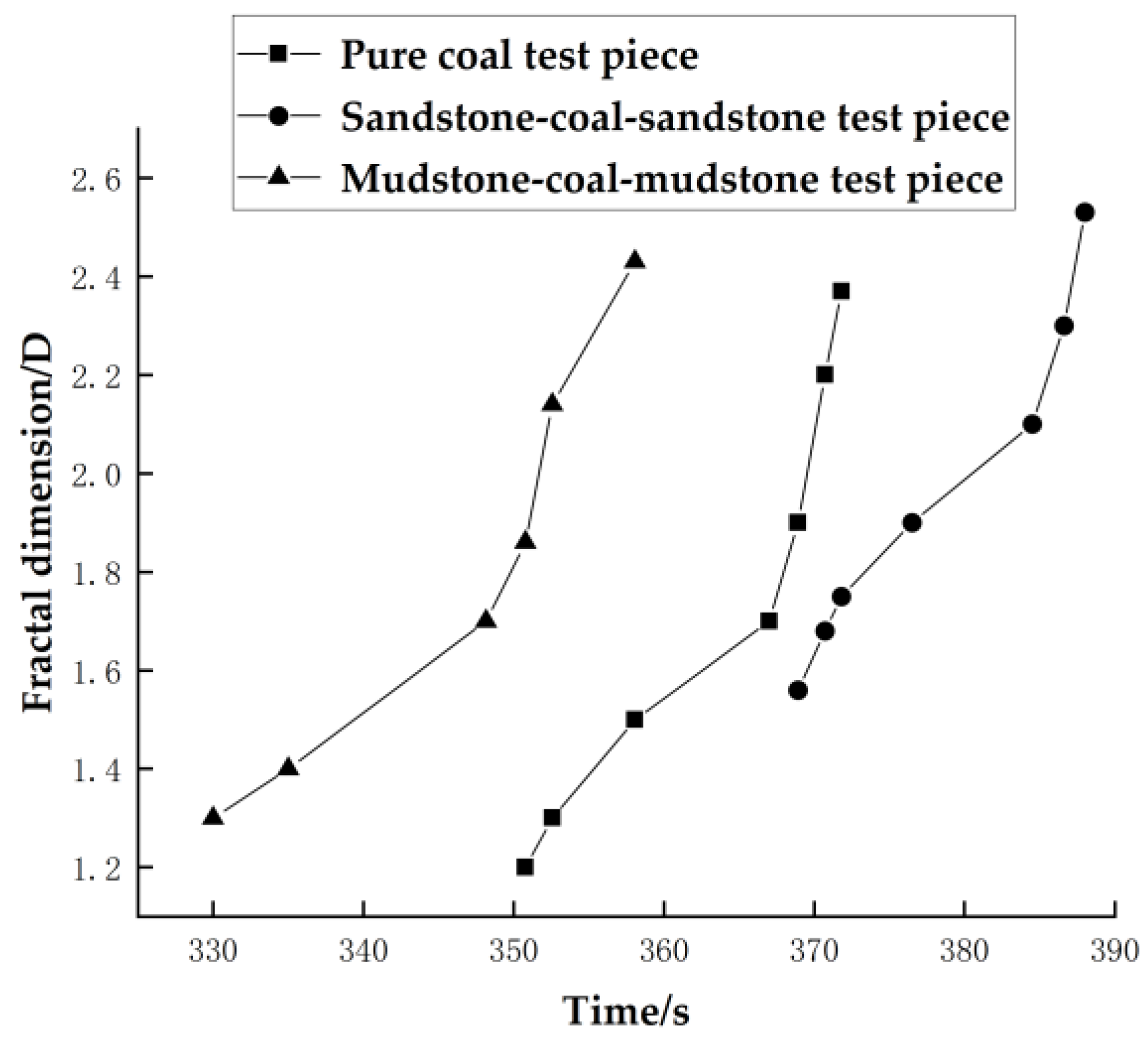
The change curve of fractal dimension D of each assembly and pure coal specimen over time is shown in Figure 13. It can be seen from the figure that under the same loading conditions, the fractal dimension of mudstone–coal–mudstone is greater than that of pure coal and the sandstone–coal–sandstone combination, that is, the degree of fragmentation is greater than that of the latter two, which indicates that the degree of destruction of the coal body under the mudstone clamping is relatively more severe, and the degree of crushing of the coal body is higher.
Combined with the above fractal results, it can be seen that the crushing degree of the coal body in the combination is greater than the crushing degree of the pure coal specimen, which indicates that the energy absorbed by the combined specimen is mainly used for the destruction of the coal body part with less strength, and the degree of crushing of the coal body is greater than that of the pure coal specimen under the same impact, and the energy released by the mudstone cannot be all consumed by the intermediate coal body due to the low stiffness of the mudstone in the combination, resulting in the coal body being relatively more prone to instability damage under the clamping of the mudstone, and the degree of crushing of the coal body is also higher.

6. Failure Mechanism Analysis of Coal and Rock System in the Main Roadway in the Panel Area

Before stoping of the main roadway in the deep panel, the coal–rock composite system was pressed. Assuming that the coal–rock composite system was regarded as a whole and divided into several micro-units, the stress state of any point in the system could be expressed by the stress component composed of normal stress σx, σy, and σz and shear stress τxy, τxz, τyx, τyz, τzx, and τzy [33,34], and could also be expressed by the stress tensor σij:
σ i j = σ x τ x y τ x z τ y x σ y τ y z τ z x τ z y σ z = σ m δ i j + S i j
During the deformation and failure of coal and rock systems, the shape change was mainly caused by stress deviation Sij, and the volume change resulted from spherical stress tensor σmδij, that is:
σ m δ i j = σ m 0 0 0 σ m 0 0 0 σ m
S i j = σ x σ m τ x y τ x z τ y x σ y σ m τ y z τ z x τ z y σ z σ m = S x τ x y τ x z τ y x S y τ y z τ z x τ z y S z
Influenced by stoping, the energy of the coal and rock system in the main roadway would inevitably change [35], assuming that the strain energy U accumulated in the coal and rock system was equal to the work We done by external forces, and all the strain energy U was converted into releasable elastic energy Ue and dissipated energy Ud, namely:
U = U e + U d = W e
In principal stress space, when the system reached a certain strain state εij, the total strain energy accumulated in the system is:
U = 0 ε i j δ U = 0 ε i j f ε = 0 ε i j σ i j d ε i j
When a large amount of energy was transformed into elastic strain energy, the coal–rock composite structure affected the distribution of stress and energy. Stress consumed energy when it led to the failure of the coal–rock system, so that the coal and rock system structure was damaged. Under the influence of stress, the residual elastic strain energy determined the impact failure degree of broken coal–rock. Stress and energy were associated through the elastic strain of the coal–rock system [36]. To explore the failure mechanism and energy evolution process of coal–rock combinations with different stiffness, the interaction mechanical model of the coal–rock system was established, as shown in Figure 14. Assuming that the stress of roof rock mass was P1, the stress of the coal mass was P2, the floor rock mass was not deformed, and the surrounding pressure P was ignored, and then:
P 1 = M 1 d 2 μ 1 d t 2 + k 1 u 1
where M1, k1, and μ1 are the mass, stiffness, and displacement of the roof, respectively. The force in the coal mass is:
P 2 = f ( μ 2 , t )
The equilibrium equation of the coal–rock system is:
k 1 + f ( u 2 , t ) 0
It can also be described by the following formula:
Δ μ 2 Δ μ = 1 1 + f ( μ 2 , t ) k 1
where Δμ2 is the displacement increment of the coal mass, and Δμ is the displacement increment of the combined coal and rock mass.
Because the components of coal–rock composite systems were different, the evolution of stress field and energy field played a certain role in the occurrence of roadway impact failure. When the elastic strain energy accumulated in the system reached the energy storage limit, it would cause damage to the system itself to a certain extent [37], which could usually be divided into steady-state failure and unstable failure.
When k1 = k3 > f′(μ2,t), that is, the coal mass was clamped by hard rock, and when the coal mass was in the pre-peak stage, the coal–rock system was in the elastic energy storage stage. Because of the high stiffness of the rock body and the strong ability to bear deformation, the early energy storage was small, and the roof rock body released elastic energy Ure, and the floor rock body released elastic energy Ufe. In this case, the coal mass was subjected to the mechanical energy, thermal energy, and other energy released by the rock body, and nonlinear compression deformation occurred. As f′(μ2,t)/(k1 + k3) decreased, Δμ2μ increased gradually. When the coal seam reached the peak point C, f′(μ2,t) declined to 0, Δμ2μ = 1, and the displacement increment of the coal mass was the same as that of the combined coal–rock system, while k1 and k3 remained basically unchanged.
Under the joint action of stress and energy, the coal mass experienced steady-state failure, thus generating irreversible plastic dissipated energy Ucc expressed by Equation (13):
k 1 + k 3 + f ( μ 2 , t ) > 0 ,   f ( μ 2 , t ) < k 1 + k 3
When k1 = k3 < f′(μ2,t), that is, the coal was clamped by soft rock, the ability of rock mass to resist deformation was weak, and a large amount of elastic energy Ure was accumulated under the action of force F. When the rock mass reached the energy storage limit, the energy was quickly released to the coal mass, and the released energy could not be consumed by the coal mass. When the coal mass reached point S2, the stress level of soft rock was high, and the coal mass was prone to impact failure, that is, k1 + k3 + f′(μ2,t) = 0, Δμ2μ→∞, the elastic energy accumulated in the rock mass was released quickly at the same time, thus accelerating the failure of the coal mass, and the whole coal and rock system released energy Ur, and the system reached an extremely unstable state, with its relation expressed by Equation (14):
k 1 + k 3 + f ( μ 2 , t ) < 0 ,   f ( μ 2 , t ) > k 1 + k 3
Thus, it could be known that when the stiffness k1 and k3 of the rock mass were less than the stiffness f′(μ2,t) of its post-peak deformation, this could very easily result in the system instability failure. In the coal and rock system, the post-peak slope of the coal mass was reduced so that elastic energy could not be accumulated, which could effectively relieve the stress around the coal mass and reduce the degree of rock burst to some extent.

7. Prevention and Control Measures of Energy Release and Impact Prevention in Coal and Rock Systems of the Main Roadway in the Panel Area

7.1. Technical Measures for Energy Release and Impact Reduction

In view of the impact phenomenon in the stoping process of Panel 1 of Gaojiapu Coal Mine and combining the influence of the stress and energy evolution of the coal and rock mass on the impact possibility of the main roadway in the panel in the previous section, it was known that different coal and rock combinations would produce stress concentration and energy accumulation in the coal mass before the impact, and excessive accumulated energy would induce the impact of the coal roadway in Panel 1. For Gaojiapu Coal Mine, with the risk of rock burst, measures were put forward to relieve the pressure, release the energy, and reduce the impact in the main roadway in the deep panel, so as to reduce the risk of rock burst.
(1) Weakening the strength and stress concentration of coal and rock mass near the main roadway in Panel 1, so that the high stress is transferred to the deep coal and rock mass;
(2) Weakening the energy of elastic strain energy stored in the coal and rock mass, and reducing the energy generated by it, so as to reduce the possibility of impact of the coal and rock mass in Panel 1 main roadway.
The schematic diagram of the dynamic impact mechanism in Panel 1 is shown in Figure 15. Before pressure relief of the coal mass, when reaching the impact point D, it corresponded to the stress point D′ before the peak of the rock mass. In this case, k1 + k3 + k2 = 0, the energy released by the rock mass could not be absorbed by the coal mass, and the impact would be induced. After pressure relief, the post-peak curve of coal became gentle. The impact point D1 of the coal mass corresponded to its pre-peak stress point D″. Compared with the stress conditions at D′ before pressure relief, the stress conditions after pressure relief were reduced, and the steady-state index corresponding to impact point D1 was γ2 = k1+ k3 + k2′. Since k2 < k2′, γ1 < γ2, the steady-state index of the coal mass was small before pressure relief, and it could reach the stress conditions at D′ more easily, which, relatively speaking, could more easily induce impact failure. After pressure relief, the steady-state index was large, the failure seemed to be more stable, and both the failure strength and stored elastic strain energy were smaller than those before pressure relief. Meanwhile, the stress concentration degree in the coal seam and the elastic strain energy storage capacity were reduced simultaneous, which, to some extent, could reduce the partial release of elastic energy from the coal mass and educe the possibility of roadway impact. Therefore, the measures of energy release and impact reduction were adopted to realize the pressure relief of high-stress roadway by arranging drill holes in the coal seam, and the surrounding rock of drill holes was deformed and damaged. Moreover, the strength of the coal mass was reduced, the loose coal blocks in the caving zone were further compacted, and the elastic strain energy was released into the hole, thus reducing the possibility of local stress concentration of surrounding rock in the main roadway, and the fracture zone around drill holes became the main zone of pressure relief.
Because the high-energy seismic source of the coal seam roadway in Panel 1 of Gaojiapu Coal Mine was mostly concentrated in the coal pillar area of the working face on the plane, and mostly concentrated in the coal seam and its adjacent roof and floor in the vertical direction, the high-energy event that caused the impact of the roadway appeared near the coal roadway (Figure 15); the coal and rock system structure in this position was a “mudstone-coal-mudstone” structure, which was consistent with the “mudstone-coal-mudstone” composite structure analyzed in the previous two sections. This revealed that when the energy was accumulated to a certain extent, the elastic strain energy accumulated in the mudstone of the roof and floor would be transferred and released to the coal seam, and the stress in the coal seam would gradually reach its own bearing limit. At this time, the coal seam could not consume the energy released by the mudstone of the roof and floor, thus causing the failure. After the coal seam was damaged, not only the remaining elastic strain energy of the coal seam could participate in the impact failure of the surrounding rock of the roadway, but also the elastic strain energy in the roof rock could be released instantly, which together caused the roadway rock burst in a large range. At the same time, it showed that the occurrence of rock burst in the main roadway in Panel 1 was not only related to the focal location and energy, but also closely related to the location of the roadway, that is, the coal–rock composite structure.

7.2. Application and Verification of Impact Reduction Measures

The energy release and impact reduction of the high-stress roadways in Panel 1 were realized by arranging drill holes in the coal seam. The main roadway in Panel 1 was selected as the statistical area. Because the prevention and control measures of pressure release, energy release and impact reduction were taken in the main roadway in Panel 1 in November, the microseismic energy distribution in Panel 1 in October and that in December were compared, as shown in Table 7. One month before the implementation of pressure relief measures, the frequency of high-energy microseismic events was higher, and one month after the implementation of pressure relief measures, the high-energy microseismic events decreased. Combining the profile distribution of microseismic events in December in Figure 16 and Figure 17, it could also be seen that the high-energy sources in this month decreased obviously. This was because the drilling construction could lead to a certain broken zone around the drill hole under the action of high stress, and the high stress transferred to the deep coal mass, which reduced the stress concentration degree of the coal seam and the ability to store elastic strain energy. Moreover, the elastic energy of the coal mass was partially released, which reduced the impact failure degree of dynamic load disturbance to the roadway and reduced the possibility of rock burst.

8. Conclusions

Based on the above experiments, combined with the fractal of the test piece fragments, the following conclusions are mainly drawn:
(1) Through the fractal analysis of the fragments of the specimen after the test, it can be seen that under the same loading conditions, the fractal dimension is mudstone–coal–mudstone > sandstone–coal–sandstone > pure coal, that is, the degree of fragmentation is the largest under the blessing of mudstone, and the next time with sandstone blessing; the pure coal structure is the smallest.
(2) The impact failure process of the coal and rock mass can be divided into typical stages, such as particle ejection, splitting into blocks, block ejection, and debris emission. It takes a long time for coal to be damaged under the clamping action of sandstone with greater stiffness, the failure strength and elastic strain energy are greater, and the impact degree is relatively more severe under the clamping action of mudstone.
(3) The loading process of the three coal–rock composite systems can be divided into three stages: absorption–accumulation–release. The maximum principal stress and elastic strain energy before the deformation and failure of the coal–rock system are mainly concentrated in the coal mass, and finally, the energy is released by the coal mass. In the pure coal system, the coal mass finally experiences an “X-shaped” shear fracture as loading proceeds. In the sandstone–coal–sandstone system, sandstone becomes the “medium” for the external environment to transmit elastic strain energy to coal, and eventually the elastic strain energy released by coal reaches all parts of the system, resulting in the system failure. In mudstone–coal–mudstone system, due to the change of the maximum principal stress, the elastic strain energy released cannot be consumed by the coal mass, finally giving rise to the co-shear fracture inside the coal and rock system.
(4) In this paper, the transformation of boundary conditions of surrounding rock in the roadway and the loading problem of dynamic and static combination are simulated by the loading path and boundary conditions of “single face unloading-five-sided static load-vertical application of medium strain rate dynamic disturbance”. The disturbance load is applied by two forms: small cycle and slope with medium strain rate, and the stiffness and strength of the coal–rock combination are studied. The force energy transmission law and its difference of the coal–rock system during the impact process are analyzed and studied. Finally, the steady-state index γ of the coal body is proposed, which is applied to guide the impact control measures of the roadways through the coal seam area. The possibility and strength of impact failure of coal under the clamping action of rocks with different stiffness are related to the γ value. The smaller the γ value, the higher the possibility and the more intense the impact. Among them, the “hard rock-coal-hard rock” system satisfies the equation k3 + f′(μ2,t) > 0, and the γ value of the coal mass is large with more stable failure if clamped by hard rock, while the “soft rock-coal-soft rock” system conforms to the equation k1+ k3 + f′(μ2,t) < 0. Under the clamping action of soft rocks, the γ value is relatively small, and the coal mass is prone to instability failure since soft rocks can easily accumulate elastic strain energy, which cannot be consumed by the coal mass when released.
(5) In the main roadway in the deep panel, pressure relief measures are adopted to reduce the stress concentration degree of the coal seam and its ability to store elastic strain energy, reduce the post-peak stiffness of the coal mass, release the energy of weak rock mass in an orderly manner in advance, block the energy transmission path, destroy the stress and energy conditions for rock burst, mitigate the impact risk of coal and rock mass, and prevent the occurrence of rock burst to some extent.

Author Contributions

Conceptualization, J.L.; methodology, J.C.; validation, W.Z., J.C. and L.D.; formal analysis, S.S. and W.R.; investigation, W.Z.; resources, J.C.; writing—original draft preparation, W.Z.; writing—review and editing, J.L.; supervision, J.L.; project administration, J.L.; funding acquisition, J.L. All authors have read and agreed to the published version of the manuscript.

Funding

This research was funded by the Natural Science Research Project of Anhui Educational Committee (KJ2021ZD0051), the Research Fund of the State Key Laboratory of Coal Resources and Safe Mining, CUMT (SKLCRSM22KF008), the National Natural Science Foundation of China (52004004) and the National Natural Science Foundation of China (U21A20110).

Data Availability Statement

The data that support the findings of this study are available from the corresponding author upon reasonable request.

Acknowledgments

J.L. was supported by the Natural Science Research Project of Anhui Educational Committee (KJ2021ZD0051), the Research Fund of the State Key Laboratory of Coal Resources and Safe Mining, CUMT (SKLCRSM22KF008), the National Natural Science Foundation of China (52004004) and the National Natural Science Foundation of China (U21A20110).

Conflicts of Interest

The authors declare no conflict of interest.

References

  1. Yuan, L. Research progress of mining response and disaster prevention and control in deep coal mines. J. China Coal Soc. 2021, 46, 716–725. [Google Scholar]
  2. Prochazka, P.P. Application of discrete element methods to fracture mechanic of rock burst. Eng. Fract. Mech. 2004, 71, 601–618. [Google Scholar] [CrossRef]
  3. Zhou, R.Z. Analysis of the occurrence law of rock burst and the mechanical mechanism of fracture. Chin. J. Geotech. Eng. 1995, 17, 111–117. [Google Scholar]
  4. Huang, Q.X.; Gao, Z.N. Mechanical model of damage fracture of roadway impact ground pressure. J. China Coal Soc. 2001, 26, 156–159. [Google Scholar]
  5. Manoj, N.B.; Petros, V. Fatigue and dynamic energy behaviour of rock subjected to cyclical loading. Int. J. Rock Mech. Min. Sci. 2009, 46, 200–209. [Google Scholar]
  6. Gao, M.S.; Dou, L.M.; Zhang, N.; Wang, K.Z.; Heng, B.S. Strength and weakness mechanical model and application analysis of surrounding rock control of impact ore pressure roadway. Rock Soil Mech. 2008, 29, 359–364. [Google Scholar]
  7. Liu, X.H.; Xue, Y.; Zheng, J.; Gui, X. Research on energy release in coal rock fragmentation process under impact load. Chin. J. Rock Mech. Eng. 2021, 40 (Suppl. S2), 3201–3211. [Google Scholar]
  8. Zhao, T.B.; Yin, Y.C.; Tan, Y.L. Development of a rock testing system with changeable stiffness and its application in the study on the rock failure mechanical behavior. Chin. J. Rock Mech. Eng. 2022, 41, 1846–1857. [Google Scholar]
  9. Zuo, J.P.; Chen, Y.; Cui, F. Differences in mechanical properties and impact tendency analysis of different coal-rock assemblages. J. China Univ. Min. Technol. 2018, 47, 81–87. [Google Scholar]
  10. Tan, Y.L.; Guo, W.Y.; Xin, H.Q.; Zhao, T.B.; Yu, F.H.; Liu, X.S. Research on key technology of impact pressure monitoring and risk solving in deep mining of coal mine. J. China Coal Soc. 2019, 44, 160–172. [Google Scholar]
  11. Eberhardt, S.S. Quantifying progressive pre-peak brittle fracture damage in rock during uniaxial compression. Int. J. Rock Mech. Min. Sci. 1999, 36, 361–380. [Google Scholar] [CrossRef]
  12. Liu, S.H. Mutation model and chaotic mechanism of failure instability of combined coal rock under dynamic and static loading. J. China Coal Soc. 2014, 39, 292–300. [Google Scholar]
  13. Liu, B.; Yang, R.S.; Guo, D.M.; Zhang, D.Z. Combined experimental study on impact tendency of deep coal rock at the level of Suncun coal mine. Chin. J. Rock Mech. Eng. 2004, 23, 2402–2408. [Google Scholar]
  14. Tutuncu, A.N.; Podio, A.L.; Grogory, A.R.; Sharma, M.M. Nonlinear viscoelastic behavior of sedimentary rocks. Part1: Effect of frequency and strain amplitude. Lead. Edge 1998, 63, 184–194. [Google Scholar]
  15. Zhao, X.Y.; Jiang, Y.D.; Zhu, J.; Sun, G.Z. Experimental Research on Precursor Information of Deformation and Failure of Coal-rock Combination. Chin. J. Rock Mech. Eng. 2008, 27, 339–346. [Google Scholar]
  16. Zhao, S.K.; Zhang, Y.; Han, R.J.; Jiang, H.B.; Zhang, N.B.; Xu, Z.J. Numerical simulation of impact tendency evolution of combined coal rock structure. J. Liaoning Tech. Univ. 2013, 32, 1441–1446. [Google Scholar]
  17. Liu, J.; Wang, E.Y.; Song, D.Z.; Yang, S.L.; Niu, Y. Effect of rock strength on mechanical behavior and acoustic emission characteristics of combined specimens. J. China Coal Soc. 2014, 39, 685–691. [Google Scholar]
  18. Lippmann, H. Mechanics of “bumps” in coal mines: A discussion of violent deformation in the sides of roadways in coal seams. Appl. Mech. Rev. 1987, 40, 1033–1043. [Google Scholar] [CrossRef]
  19. He, M.C.; Sousa, L.R.E.; Miranda, T.; Zhu, G.L. Rock burst laboratory tests database Application of data mining techniques. Eng. Geol. 2015, 185, 116–130. [Google Scholar] [CrossRef]
  20. Du, L.M.; Mou, Z.L.; Cao, A.Y.; Gong, S.Y.; He, H.; Lu, C.P. Prevention and Control of Coal Mine Impact Mine Pressure; Science Press: Beijing, China, 2017. [Google Scholar]
  21. Lau, J.S.O.; Chandler, N.A. Innovative laboratory testing. Int. J. Rock Mech. Min. Sci. 2004, 41, 1427–1445. [Google Scholar] [CrossRef]
  22. Fuenkajorn, K.; Sriapai, T.; Samsri, P. Effects of loading rate on strength and deformability of MahaSarakham salt. Eng. Geol. 2012, 135–136, 10–23. [Google Scholar] [CrossRef]
  23. Ghamgosar, M.; Bahaaddini, M.; Erarslan, N.; Williams, D.J. A new experimental approach to quantify microfractures in the Fracture Process Zone (FPZ) under various loading conditions. Eng. Geol. 2021, 283, 106024. [Google Scholar] [CrossRef]
  24. Nezhad, M.M.; Fisher, Q.; Gironacci, E.; Rezania, M. Experimental study and numerical modeling of fracture propagation in shale rocks during Brazilian disc test. Rock Mech. Rock Eng. 2018, 51, 1755–1775. [Google Scholar] [CrossRef] [Green Version]
  25. Zhang, Z.Z.; Gao, F. Experimental study on energy evolution characteristics of three rocks. J. China Univ. Min. Technol. 2015, 44, 416–422. [Google Scholar]
  26. Zhang, Z.Z.; Gao, F. Experimental investigation on the energy evolution of dry and water saturated red sandstones. Int. J. Min. Sci. Technol. 2015, 25, 383–388. [Google Scholar] [CrossRef]
  27. Niu, S.J.; Ge, S.S.; Yang, D.F.; Dang, Y.-H.; Yu, J.; Zhang, S. Mechanical properties and energy mechanism of saturated sandstones. J. Cent. South Univ. 2018, 25, 1447–1463. [Google Scholar] [CrossRef]
  28. Mandelbrot, B.B. Fractals: Form, Chance and Dimension; W. H. Freeman: San Francisco, CA, USA, 1977. [Google Scholar]
  29. Cannon, J.W. The Fractal Geometry of Nature. By Benoit, B. Mandelbrot. Am. Math. Mon. 1984, 91, 594–598. [Google Scholar] [CrossRef]
  30. Tyler, S.W.; Wheat-craft, S.W. Fractal Scaling of Soil Particle-size Distributions: Analysis and Limitations. Soil Sci. Soc. Am. J. 1992, 56, 362–369. [Google Scholar] [CrossRef]
  31. Katz, A.J.; Thompason, A.H. Fractal sandstone Pores: Implications for conductivity and pore formation. Phys. Rev. Lett. 1985, 54, 1325–1328. [Google Scholar] [CrossRef]
  32. Falconer, K.J. Fractal Geometry: Mathematical Foundations and Applications; Wiley: Bristol, UK, 1989. [Google Scholar]
  33. Li, J.Z.; Xie, G.X.; Wang, L.; Li, Y. Mechanical mechanism of dynamic fracture evolution of coal floor unloading in deep mining. J. Min. Saf. Eng. 2017, 34, 876–883. [Google Scholar]
  34. Xie, H. Research review of the state key research development program ofChina:Deep rock mechanics and mining theory. J. China Coal Soc. 2019, 44, 1283–1305. [Google Scholar]
  35. Yu, H.; Li, X.J.; Li, B.Y. Macro-micro mechanical response and energy mechanism of surrounding rock under excavation disturbance. J. China Coal Soc. 2020, 45, 60–69. [Google Scholar]
  36. Qi, Q.X.; Li, H.T.; Zheng, W.J. Physical model and measurement method forcelastic deformation energy characterization of coal and rock. Coal Sci. Technol. 2022, 50, 70–77. [Google Scholar]
  37. Ang, L.; Gao, F.Q.; Wang, X.Q. Energy evolution law and failure mechanism of coal-rock combined specimen. J. China Coal Soc. 2019, 44, 3894–3902. [Google Scholar]
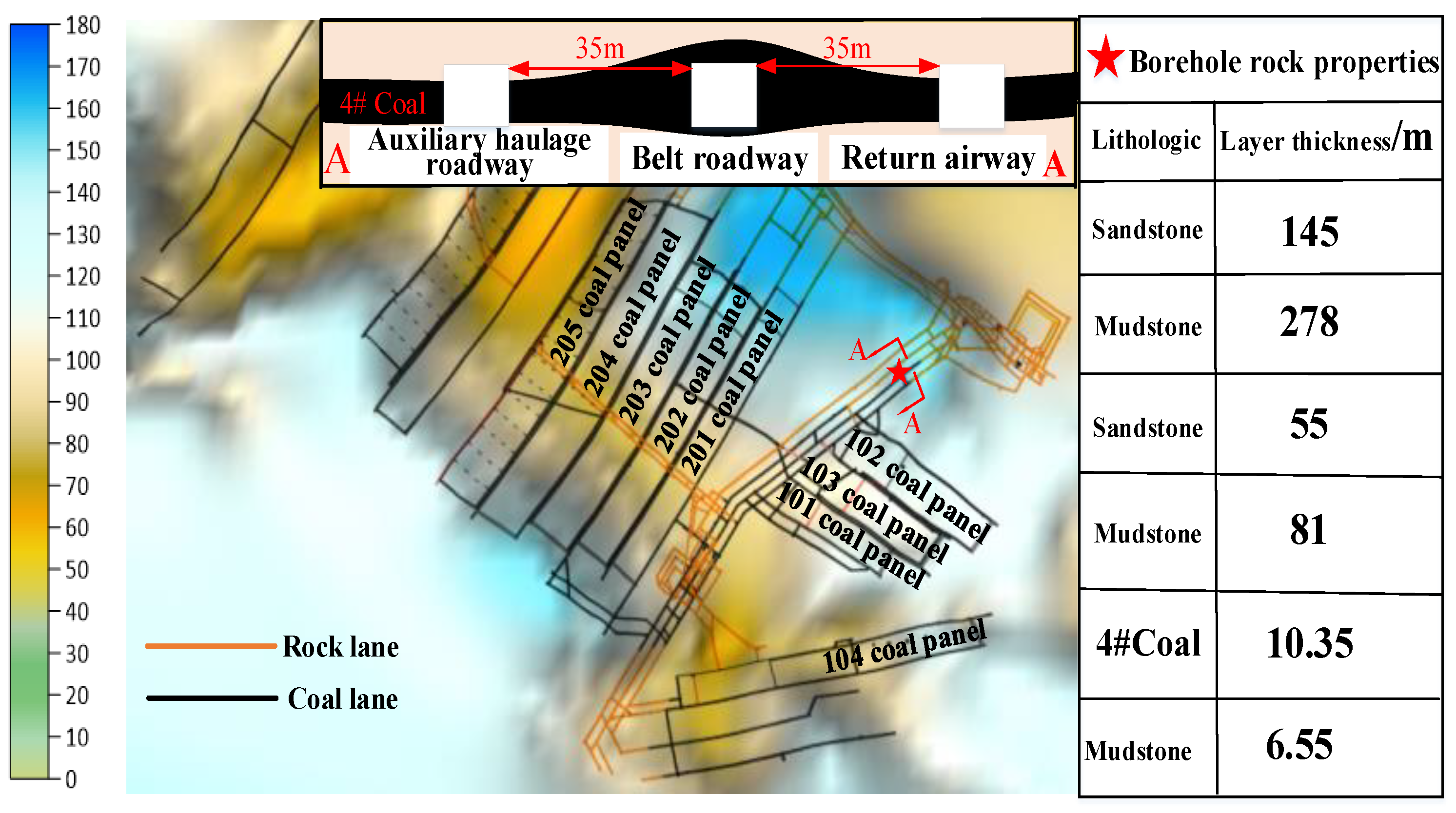
Figure 1. Distribution map of large alley group in disk area. (A-A: Section view of Gaojiapu roadways).
Fractalfract 07 00550 g001
Figure 2. Plane distribution map of microseism events in August.
Fractalfract 07 00550 g002
Figure 3. Typical roadway surrounding rock structure and its coal–rock mass combination: (a) rock–coal–rock; (b) rock–coal; (c) coal–rock; (d) coal.
Fractalfract 07 00550 g003
Figure 4. Test system and finished product diagram of coal and rock mass: (a) Dynamic manifestation test; (b) Three-axis loaded parts; (c) The 75 × 75 × 100 mm Specimen fixture; (d) Coal–rock mass processing products fixture system of mining coal mass.
Fractalfract 07 00550 g004
Figure 5. Stress loading path of coal–rock mass.
Fractalfract 07 00550 g005
Figure 6. Correlation curves of physical energy of different coal and rock combinations: (a) Stress–strain relationship; (b) Elastic energy–strain relationship; (c) Elastic energy–time relationship.
Fractalfract 07 00550 g006
Figure 7. Failure and impact of different coal and rock masses: (ad) Coal, (eh) Sandstone–coal–Sandstone, (il) Mudstone–coal–Mudstone.
Fractalfract 07 00550 g007
Figure 8. Nephogram of maximum principal stress evolution of three coal–rock systems. (I and III: Parameters assigned to coal, sandstone, mudstone, II: Parameters assigned to the coal body).
Fractalfract 07 00550 g008
Figure 9. Nephogram of evolution of elastic strain energy in three coal–rock systems. (I and III: Parameters assigned to coal, sandstone, mudstone, II: Parameters assigned to the coal body).
Fractalfract 07 00550 g009
Figure 10. Nephogram of plastic zone evolution in three coal–rock systems. (I and III: Parameters assigned to coal, sandstone, mudstone, II: Parameters assigned to the coal body).
Fractalfract 07 00550 g010
Figure 11. Evolution of energy with strain in different coal–rock systems: (a) Coal system; (b) Sandstone–coal–Sandstone system; (c) Mudstone–coal–Mudstone system.
Fractalfract 07 00550 g011
Figure 12. Stress–strain curves of different coal–rock systems: (a) Pre-peak stress–strain curves of different coal–rock systems; (b) Total stress–strain curves of coal under different rock systems.
Fractalfract 07 00550 g012
Figure 13. Fractal dimension D variation curve of coal–rock sample.
Fractalfract 07 00550 g013
Figure 14. Mechanical model of interaction between coal and rock systems.
Fractalfract 07 00550 g014
Figure 15. Schematic diagram of the impact power display mechanism of a plate area.
Fractalfract 07 00550 g015
Figure 16. Profile distribution of microseismic events in August.
Fractalfract 07 00550 g016
Figure 17. The profile distribution of microseismic events in the first Pan region in December.
Fractalfract 07 00550 g017
Table 1. Statistics of seismic dynamic load strain rate range in coal mines.
NumberMonitor Energy/KJFrequency/HzMaximum Particle Peak Vibration Rate/m/sStrain Rate/×10−3 s−1
10.2965~300.13~0.41.65~3.0
20.45~300.18~0.662.3~50
30.8953~280.20~0.651.5~46
41.243~250.20~0.841.5~53
58.272~180.34~1.001.7~46
622.62~180.79~3.444.0~160
727.11~150.44~3.5011~130
850.42.5~150.50~3.273.2~120
91030.5~121.23~3.651.6~110
1039700.4~58.45~12.278.6~160
Table 2. Characteristic parameters in loading process of different coal and rock mass.
Specimen No.Failure Strength
/MPa
Strain at Peak PointEnergy at Peak Point
/MJ·m3
Incubation Time of Failure/sPost-Peak Dynamic Failure Time/s
Coal23.960.0460.53284.50
Sandstone–coal–Sandstone38.930.0390.7658.511.50
Mudstone–coal–Mudstone31.660.0410.7344.399.91
Table 3. Failure and impact of different coal and rock masses.
LithologyBulk Modulus/GPaShear Modulus/GPaDensity
/kg·m−3
Cohesion/MpaInternal Friction Angle/°Tensile Strength/GPa
Sandstone12827002.00450.2
Coal4.92.0113801.25320.15
Mudstone2.562.3625302.16360.75
Table 4. Characteristic parameters of force and energy in three stages of local coal body in three coal–rock systems.
Coal and Rock SystemAbsorption StageAccumulation StageRelease Stage
Maximum Principal Stress/MPaElastic Strain Energy/J·m3Maximum Principal Stress/MPaElastic Strain Energy/J·m3Maximum Principal Stress/MPaElastic Strain Energy/J·m3
Coal system1.52.71 × 10232 × 1030.61.75 × 103
Sandstone–coal–Sandstone system39.81 × 10263.49 × 10422 × 104
Mudstone–coal–Mudstone system52 × 10473.35 × 10422.91 × 104
Table 5. Characteristic parameters of energy and strain in different coal–rock systems.
Coal and Rock SystemStrainStrength/MPaElastic Strain Energy/JProportion of Elastic Strain Energy AccumulatedProportion of Elastic Strain Energy Released
Coal system0.011 × 10−319.962.34 × 10479.06%85.27%
0.028 × 10−332.424.19 × 104
0.075 × 10−33.906.17 × 103
Sandstone–coal–sandstone system0.015 × 10−389.046.74 × 104118.10%98.69%
0.08 × 10−3123.521.47 × 105
0.17 × 10−321.662.00 × 103
Mudstone–coal–mudstone system0.014 × 10−350.114.05 × 10484.45%95.26%
Table 6. Curve fitting parameter table of different coal and rock systems.
Coal and Rock SystemPre-Peak Linear EquationPre-Peak InterceptPre-Peak SlopePost-Peak Linear EquationPost-Peak InterceptPost-Peak Slope
Coal systemy1 = 1158.56x1 + 5.075.07 ± 0.991158.56 ± 59.79y1′ = −18.46x1 + 12.6512.65 ± 0.05−18.46 ± 0.22
Sandstone–coal–Sandstone systemy2 = 930.17x2 + 63.8763.87 ± 2.07930.17 ± 45.02y2′ = 760.15x2 + 61.2361.23 ± 1.51−760.15 ± 122.72
Mudstone–coal–Mudstone systemy3 = 528.99x3 + 35.8235.82 ± 1.17528.99 ± 35.83y3′ = 450.51x3 + 35.5235.52 ± 0.74−450.51 ± 11.40
Table 7. Statistical table of microseismic energy frequency in Panel 1 of Gaojiapu Coal Mine.
Energy RangeDate
10.1~10.3111.1~11.3012.1~12.31
102~103 J648125101
103~104 J16417719
104~105 J231
Above 105 J 771
Disclaimer/Publisher’s Note: The statements, opinions and data contained in all publications are solely those of the individual author(s) and contributor(s) and not of MDPI and/or the editor(s). MDPI and/or the editor(s) disclaim responsibility for any injury to people or property resulting from any ideas, methods, instructions or products referred to in the content.