Article

A Unified Description of the Electrical Properties with Complex Dynamical Patterns in Metal Halide Perovskite Photovoltaics

by
Enrique Hernández-Balaguera
* and
Diego Martin-Martin
Escuela Superior de Ciencias Experimentales y Tecnología (ESCET), Universidad Rey Juan Carlos, Móstoles, 28933 Madrid, Spain
*
Author to whom correspondence should be addressed.
Fractal Fract. 2023, 7(7), 516; https://doi.org/10.3390/fractalfract7070516
Submission received: 31 May 2023 / Revised: 22 June 2023 / Accepted: 24 June 2023 / Published: 29 June 2023
(This article belongs to the Section Mathematical Physics)

Abstract

:
One of the most promising emerging photovoltaic technologies is represented by perovskite materials essentially due to their outstanding performance. However, the complex fundamental understanding of relevant device physics is challenging, making it harder to obtain correlations with efficiency and long-term stability, and thus definitely transforming the landscape of solar energy. In electrical terms, perovskite solar cells often show different types of experimental behaviors at long timescales (light-enhanced capacitance and chemical inductor) in separate voltage domains, but with permanent deviations from the ideal pattern (Cole–Cole relaxation processes, fractional dynamics, and beyond). Here, we reevaluate the dynamical behavior of a photovoltaic perovskite model that leads to the two versions of constant-phase element behavior in the impedance response. Our general theory is, therefore, able to explain naturally the vast majority of results concerning the nonlinear polarization mechanisms of perovskite solar cells, extending the mathematical framework from the perspective of fractional-order electrical circuits. In this context, we discover a novel property that reveals the anomalous electrical coupling of memory effects in photovoltaic perovskites. We hope that this work can provide a useful tool for modeling experts and device physicists belonging to the photovoltaic community, moving forward toward addressing the outstanding challenges in this fast-developing field.

1. Introduction

Perovskites promise to be undoubtedly the next-generation star material in different research fields. In recent years, this emerging technology has demonstrated a fantastic future to potentially rival traditional materials, acting, for instance, as solar cells [1], photodetectors [2], memristors [3], or light-emitting diodes [4]. Nevertheless, mixed organic–inorganic halide perovskites provide a large space for exploratory research due to their significantly slow ionic conductivity, in addition to the classical electronic semiconductor properties, which naturally modify the interfaces and produce significant changes in device operation [5]. According to this complex multi-timescale dynamics, perovskite devices involve intrinsic memory conductance properties that lead, from a large body of evidence, to the need for careful device modeling and detailed electrical parameter analyses.
For the specific application of photovoltaics, the most successful device model able to explain the interplay between ionic and electronic charge transfer together with memory effects in perovskites has been the surface polarization model [6,7]. It offers, in electrical terms, a general perspective of the diversity of dynamic current–voltage hysteresis and complex impedance spectra found in the literature, through an equivalent circuit obtained from the linearized current–voltage equations. Elementary relaxation processes, consisting of combinations of resistances and capacitances, emerge as result of the recombination and accumulation of charges in perovskite solar cells [8]. Additionally, a chemical inductance [9] appears in the model as a necessary feature to explain the experimental results (negative capacitances in impedance [10], inverted hysteresis in current–voltage curves [11], and negative spike components in transient analysis [12]) with an explanation, based on the introduction of a delay equation related to memory effects, of the physical mechanism that creates it. Nevertheless, it is evident, from the abundant experimental data of scientific literature, that the relaxation processes of photovoltaic perovskites in general are rather non-Debye patterns, particularly power-law profiles. On the one hand, the impedance spectra do not exhibit, in the complex plane, the expected semicircles of a lumped-element circuit, displaying instead a frequency dispersion (i.e., Cole–Cole behavior) [13,14]. The current responses from time transient techniques, on the other hand, also point to an anomalous behavior (in particular, a steep decline followed by a long-tailed form) different from the classical exponential functions [15,16]. Both nonideal dynamics, mathematically equivalent under small-signal conditions via the Laplace transform, constitute the basic ingredient that leads us to think that the introduction of fractional calculus is indeed necessary to reformulate this already relevant model (recently unified with another explanations in the literature [17]) and, thus, cover the reality behind the experimental data across several types of measurement techniques.
Against this background, the topic of this paper is to develop a unified explanation of the anomalous phenomenology observed in perovskite solar cells by means of a reformulation of the surface polarization model that captures, with great fidelity, the experimental data with nonideal and dissipative traces. First, we introduce a generalization of the original theory, described here by two fractional-order nonlinear differential equations, analyzing the new properties that arise from impedance spectroscopy measurements. In addition to the previously reported correlation of time constants in perovskites, an advanced electrical coupling in the crossover dynamics from capacitive to inductive dispersion is unraveled to support the experimental impedance spectra. Lastly, we present in detail an example of a perovskite solar cell to show the insights of the proposed framework of analysis and to provide a decisive progress in the understanding and characterization, from a general perspective, in order to explain the real experimental results across different measurement techniques.

2. Device Modeling

2.1. Advanced Surface Polarization Model

The standard electrical model for describing the DC response of a solar cell is shown in Figure 1a. In this circuit, the current source j ph is defined by the photogeneration of electron–hole pairs in the device, the ideal diode element represents the carrier recombination processes, and the two resistances R sh and R s account for the charge losses across the cell and parasitic ohmic effects (contacts, wires, etc.), respectively. Additionally, a time-varying constant-phase element is introduced here by a nonlinear polarization mechanism with fractional dynamics under the central assumption of the internal crossfire of ionic and electronic kinetics in perovskite materials. In that element, C α is a pseudo-capacitive parameter (in units of Fs α 1 ), and the exponent α is a dispersion coefficient that quantifies the deviation from the ideality (i.e., α = 1 ), both time-dependent C α t and α t . The resulting model can sensibly be termed as an “advanced surface polarization model” that is able to reproduce and explain the misunderstandings of the electrical behavior and, additionally, provide a realistic high-fidelity description of the complex processes observed in the literature.
Our theory, based on a generalized dynamic electrical model, establishes that the total current j is composed of the summation of the recombination current j rec , the leakage current of constant value j sh , and the current of extracted excess electrons from the contact layer side j CPE , minus the photocurrent j ph [6,7,18]:
j = j rec + j sh + j CPE j ph ,
where
j rec = j rec 0 exp q V j R s n K B T 1 ,
j sh = V j R s R sh ,
where q is the elementary charge, j rec 0 is a recombination parameter, V is the voltage, n is the diode ideality factor, and K B T is the thermal energy.
Compared to previous studies [18,19], we modify the last original term in Equation (1) ( j c = d Q c d t considering the current flowing through an ideal capacitive element C ), being now expressed in terms of a variable fractional-order derivative ( d α d t α ,   0 < α 1 ). Indeed, the classical charge–voltage Q c V c and current–voltage j c V c relations in time-varying linear and ideal capacitors, Q c =   C V c and j c = C d V c d t + d C d t V c , evolve into a new capacitor theory analyzable from the perspective of fractional calculus. A significant and lively debate has taken place in the literature, in this sense, with different formulations based on the convolution operation that currently generate some doubts on the correct way of modeling, in the time-variant case, the fractional-order capacitors that follow the Curie–von Schweidler law [20,21,22]. Here, we consider the theory recently proposed in [22] consisting of the expressions d 1 α Q CPE d t 1 α = C α V CPE and
j CPE = d α C α V CPE d t α = 1 Γ α 0 t C α t τ V CPE t τ V CPE t τ α + 1 d τ ,
where it has been selected, without loss of generality, the variable fractional order in the Liouville sense to consider this situation with a great degree of complexity [23]. As previously indicated, the derivative operator is time-dependent, thus leading to a variable-order fractional system. In the literature, a wide variety of definitions of the time-varying non-integer order differentiator exist [23,24]. Substituting Equations (2)–(4) in Equation (1), considering V CPE = V j R s , and rearranging terms, one can obtain the following fractional-order differential equation:
R s d α j C α d t α = j rec 0 exp q V j R s n K B T 1 j R s R sh + 1 + V R sh + d α C α V d t α j ph .
Note that, for C α = 0 (which is not the case here), Equation (5) results in the classical characteristic equation of the static electrical model [18]:
j rec 0 exp q V j R s n K B T 1 j R s R sh + 1 + V R sh j ph = 0 .
More generally, we can reformulate the displacement capacitive–nature current j CPE , belonging to a complex and time-variant fractional-order capacitive structure, in terms of capacitive components, ideal and nonideal, with well-separated linear–nonlinear dynamics:
j CPE = C g d V CPE d t + C α d α V s d t α ,
where C g is, on the one hand, the constant geometrical capacitance that captures the most basic polarization mechanisms from a solar cell via the dielectric constant of the perovskite material [25]. While this initial term models dielectric relaxation processes corresponding to passive linear effects, on the other hand, the second capacitive response to mention, C α d α V s d t α [26], is that of surface charging process (i.e., a nonlinear polarization component with fractional kinetics) [6,7,18,19]. Before proceeding with the analysis, it should be indicated the distinction between the total applied voltage V (instantaneously variable) and the surface polarization voltage V s that responds by slow internal kinetics and determines the excess charge density of holes and ions at the accumulation layer, compensated by electrons at the contacts. Under steady-state polarization, the surface voltage reaches the strived equilibrium value V V bi , where V bi is the built-in voltage. Equation (5) then becomes
R s C g d j d t = j rec 0 exp q V j R s n K B T 1 j R s R sh + 1 + V R sh + C g d V d t + C α d α V s d t α j ph .
To better analyze the electrical properties of the halide perovskites operating under real-world conditions, we present the novel surface polarization model in a transient situation [6] with reasonable numerical approximations. The recombination current at the interface is now given by
j rec = j rec 0 exp V s + V bi / γ + V / β K B T / q ,
where γ and β are ideality parameters ( γ = 2 and β = 1 in the ideal case), i.e., n = γ β γ + β . Note that Equation (2) represents the steady-state current–voltage characteristic in the form of the diode equation after including the constant dark current in reverse bias. In Equation (9), we consider that R s and R sh have negligible effects (ideally no effect) from a practical point of view: R s 0 and R sh . Thus, V is the voltage across the constant-phase element ( V CPE = V ), and j sh 0 . Hence, we finally obtain
j = C g d V d t + j rec 0 exp V s + V bi / γ + V / β K B T / q + C α d α V s d t α j ph .
Our generalization of the surface polarization model concludes from the assumption that this interfacial charge distribution is strongly affected by the presence of ions; therefore, V s cannot follow the applied voltage V instantaneously, as previously anticipated. The relaxation equation defining this non-Debye behavior is here described as follows [7,11,14]:
τ kin ϕ d ϕ V s d t ϕ = V s + V V bi ,
in order to consider the experimental data occurring in a real-world situation. It is clearly seen that V s is the key variable that is linked to the memory effects by a characteristic kinetic relaxation time τ kin , governed by the ionic motion and its eventual accumulation at the device interfaces [17,27]. More importantly, ϕ represents the order of the slow fractional derivative with nonlocal features (as in the case of non-integer order derivative α ) since it takes into account the whole past of V s and not just the immediate activity of the surface voltage proceeding a given instant t . Note that, for generality, we select different fractional orders, α and ϕ , thus introducing bifractional kinetics [28] in the system under study.

2.2. On the Impedance Spectroscopy Dynamics

Clearly, Equations (10) and (11) have the structure of a chemical dispersive inductor [14]:
j = C g d V d t + 1 R I f V , x + C α d α x d t α ,
τ kin ϕ d ϕ x dt ϕ = g x , V ,
where the voltage V s is the slow delay variable x , thus implying that the conduction channel and the internal voltage-driven recovery function are defined by 1 R I f V , V s = j rec 0 exp V s + V bi / γ + V / β K B T / q and g V s , V = V s + V V bi [17], respectively. V V bi represents the steady-state value of the internal recovery current that remains when the transient effect is over. It is worth remembering that the last channel in the right-hand side of Equation (10) (excluding j ph ) is “slow” in the sense that the adaptation time constant τ kin is much larger than the charging time constant of the first components.
In order to analyze the impedance response of our surface polarization model, we calculate the small-signal functions by linearization of Equations (10) and (11):
j ^ = j ω C g V ^ + j ¯ rec q V ^ s γ K B T + q V ^ β K B T + j ω α C α V ^ s ,
V ^ s = V ^ 1 + j ω τ kin ϕ ,
where, in this case, the small AC perturbation quantities are denoted by tildes and s = j ω , in terms of the angular frequency ω added to the steady-state features, is indicated by an overbar. Substituting Equation (15) into Equation (14) and with some additional algebraic operations, we obtain the expression of the device impedance, which takes the following form:
Z ω = V ^ j ^ = j ω C g + 1 R rec + 1 R L + j ω ϕ L ϕ + 1 R C + 1 j ω α C α 1 ,
where the equivalent circuit elements have the following values in terms of the model parameters:
R rec = β k B T q j ¯ rec ,   R L = γ k B T q j ¯ rec ,   L ϕ = γ k B T q j ¯ rec τ kin ϕ ,   R C = τ kin ϕ C α .
The equivalent circuit is shown in Figure 1b. R rec and R L are the two branches of the recombination resistance, while R C is the resistance for ionic relaxation that does not contribute to the total DC resistance, R dc = 1 R L + 1 R rec 1 . L ϕ denotes the chemical pseudo-inductance which has the units of H s 1 ϕ .
It is worth noting the property of near continuity of fractional exponents α and ϕ in the transition from capacitive to inductive response so that R C theoretically represents an ideal (frequency-independent) resistance and not again a constant-phase element with a very low associated exponent, close to 0. It can be, therefore, stated that
α = ϕ ,
indicating that the emergence of both versions of the constant-phase element, the “heart of the slow response of perovskite materials” in electrical terms, have a common origin.
To further explore the device operation on the basis of impedance analysis, we calculate the time constants corresponding to the equivalent circuit of Figure 1b. In principle, one can define two separate time constants, associated with capacitive and inductive phenomena [29,30]:
τ C = R C C α 1 α ,         τ L = L ϕ R L 1 ϕ ,
which, nevertheless, yield the same value for the two branches of the slow mode in perovskites [10,17]:
τ C = τ L ,
if, in this context, of fractional dynamics, the constraint of Equation (18) is satisfied. The original surface polarization model in perovskites [6,7] explained this continuity property of time constants (around the value of τ kin ) as an electrical charge coupling that can produce different shapes in the impedance spectra (e.g., double capacitive arcs with and without chemical inductors, loops at intermediate frequencies, and/or spirals) [17,27]. However, the identification of common features considering the realistic slow and anomalous mechanisms was not previously taken into account so far for such complex capacitive-inductive dynamical patterns as result of the ionic–electronic coupling exhibited by photovoltaic perovskites.

3. Results and Discussion

To validate the model, the device structure FTO/c-TiO2/m-TiO2/perovskite/spiro-OMeTAD/Au was selected as representative for a perovskite solar cell with a nominal composition of Cs0.05MA0.15FA0.80Pb1.05(Br0.15I0.85)3 for the active layer. All fabrication procedures and electrical characterization are described in the Supplementary Material.
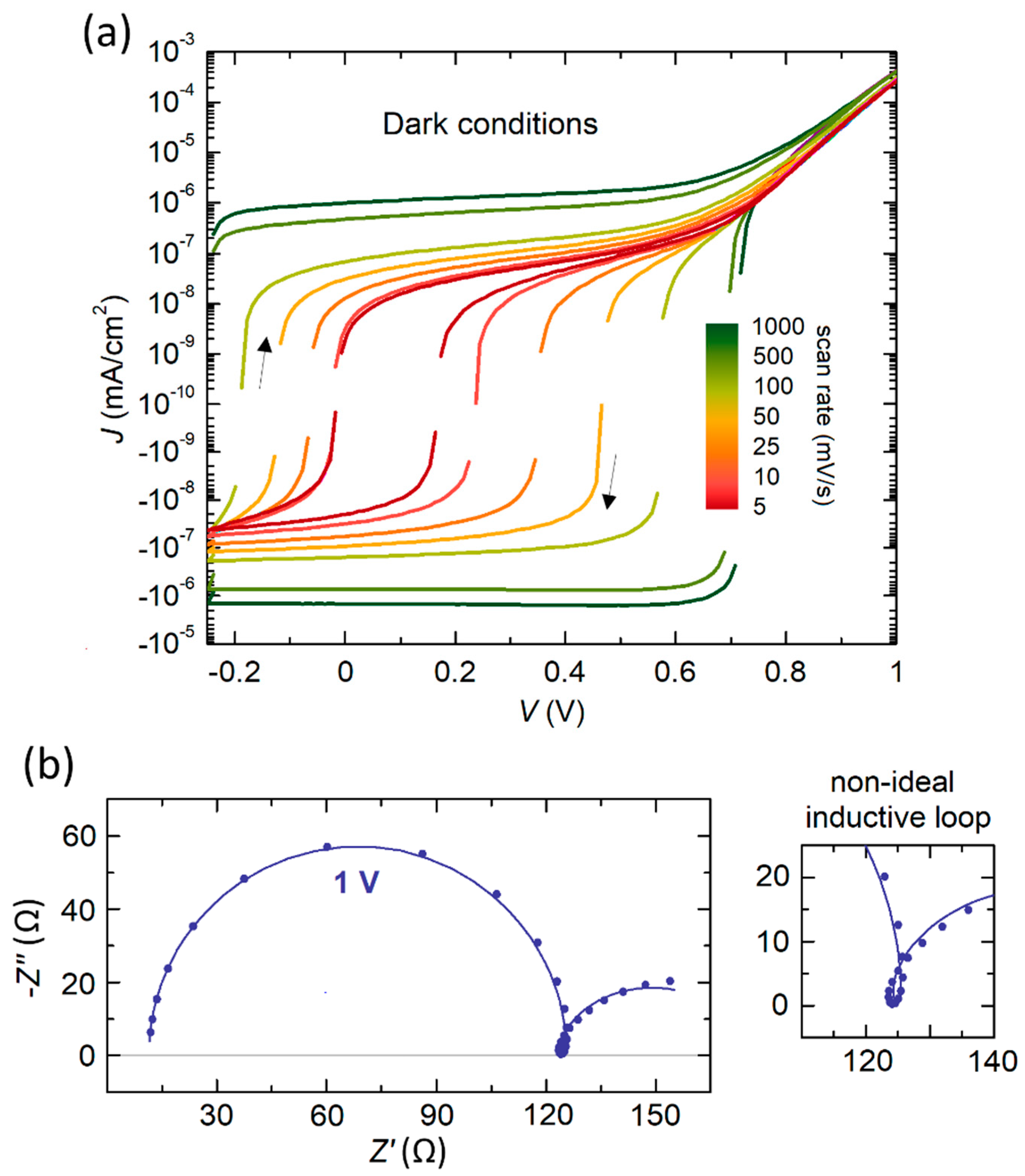
The current–voltage curves in the dark at different scan rates in Figure 2a show intense capacitive hysteresis without the influence of inductive effects, even when the voltage speed is reduced. Impedance measurements at high voltages exhibit middle-frequency range features of inductive origin that do not affect or barely change the capacitive arcs in the complex plane spectra, due to the low values of pseudo-inductance L ϕ (around 10 H s 1 ϕ ). As an example, Figure 2b shows the impedance response measured at a DC bias voltage of 1 V. By increasing the value of the bias voltage, the inductive loop commonly emerges as a dominant feature of the device operation, a fact well stablished in perovskite solar cells. In effect, the Nyquist plot of Figure 2b, with a mixture of complicated phenomena, provides a good opportunity to compare the slow capacitive and inductive behavior, as well as validate the theoretical analysis previously reported. In Figure 2b, we also show the fitting with the results of interest. Values of the characteristic parameters associated to the inductive phenomenology ( τ L and ϕ ) are similar to those obtained for the capacitive effects ( τ C and α ). We take these good agreements between capacitive and inductive mechanisms of slow and anomalous origin (23.15 ms and 16.95 ms; 0.65 and 0.66) as encouraging support of our advanced surface polarization model, but we go a step further by examining our theory in illuminated solar cells.
Hereinafter, we focus on a particular illumination intensity of 100 mW/cm2 (i.e., 1 Sun). In Figure 3a, it is clearly observed that there are now two loops in the current–voltage curve, where the current in forward and backward makes a crossing pathway. This effect indicates a transition from regular to inverted hysteresis [19,31,32] as the voltage increases, caused by the appearance of the chemical inductor in the impedance spectra. Next, we analyze the transformation region around this change in behavior. Nyquist plots at relatively low voltages manifest as two neatly distinguished capacitive semicircles (Figure 3b). Nevertheless, at a voltage domain, a transformation of or change in the equivalent circuit occurs in which the low-frequency positive arc vanishes and gives rise to an inductive loop in the positive complex half-plane, as is shown the Figure 3c. Note that the term “transformation” refers to the simplified version of the equivalent circuit of Figure 1b since the electrical components of the model are not present in the entire voltage range. The values calculated from the impedance data corresponding to Figure 3b,c, using the equivalent circuit of Figure 1b, are detailed in Table 1. As in other studies [29,30], the value of the geometrical capacitance, constant and independent of the voltage, is on the order of hundreds of nanofarads (for high frequencies).
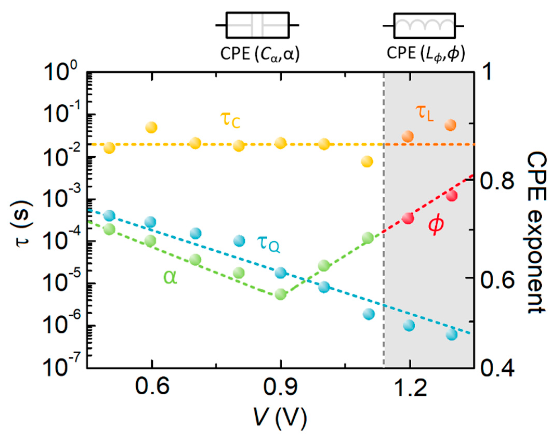
The practical problem under study here is that both types of impedance spectra exhibit a significant frequency dispersion in the low frequency region (appearing as flattened arcs in the first and fourth quadrant, respectively), which is the usual case for real measurement data [13,14,15,16,33]. When the data of Figure 3b,c are fitted and the correspondent time constants and fractionary exponents are obtained, we corroborate an important result. The transition from capacitive to inductive spectra leads to slight variations in the associated time constants at sufficiently low frequencies (refer to Figure 4) [10,30] and, importantly, the fractional order remains approximately constant and continuous, maintaining the slight change trend across the transformation of the equivalent circuit. This striking coincidence, shown in Figure 4, leads us to think that the physical origin in the emergence of the constant-phase element behavior is the same although both mechanisms exhibit a different electrical nature. However, α and ϕ essentially present different trends as a function of the voltage in this advanced coupling of perovskites. The evolution of the fast and ideal time constant τ Q , obtained as R rec C g [14,31], is also presented in Figure 4.
For the case of capacitive behavior in the low-voltage region, the authors previously reported the relationship between C α and α as a function of the voltage when τ C is held invariable [13]. We now study the inductive version of the constant-phase element. If τ L for the slow relaxation phenomena at high voltages is constant and independent of the voltage, and if R L mimics the exponential dependence on voltage of a recombination element, L ϕ and ϕ must show opposite tendencies. As the voltage increases, the pseudo-inductance decreases, as shown in the literature, and the fractional order ϕ contrarily increases toward the ideal case. Specifically, the value of the constant-phase element parameters, by considering the inductive face, can be examined from the relation ϕ = ln L ϕ R L 0 + q V n K B T ln τ L , ref , where R L 0 typically serves as a fitting parameter ( R L = R L 0 exp q V n K B T ) and τ L , ref denotes a reference value of inductive time constant (e.g., estimated in dark). It is interesting to speculate on the implications of the characteristics of such distribution with a decreasing width as the bias voltage increases. The coupling relationship involves interfacial quantities such as the recombination resistance R L and a characteristic time constant τ L postulated approximately from the maximum imaginary impedance. Hence, our analysis generalizes the universal theory proposed in [34] to other types of dispersive effects associated with inductive processes of chemical origin.
We use this discussion to provide some indications that should be considered in future works. The advanced surface polarization model can be extended to provide a quantitative explanation, in terms of large transient currents, of different typical hysteretic features that occur in measurements from forward to reverse voltage scans via direct fitting of current–voltages curves obtained in different conditions, as realized with the original model [6,18]. Nevertheless, specific and advanced requirements on the design of the nonlinear least-squares fitting method should be fulfilled in relation to the fractional calculus theory.

4. Conclusions

We revisited the electrical responses of halide perovskite solar cells governing the device operation. Specifically, we introduced a dynamic electrical model to describe the rich variety of behaviors associated with the inherent complexity of this representative of the next generation of photovoltaics. The traditional nonlinear polarization model for perovskite materials was generalized and expanded in a coherent way regarding the most common experimental measurements. The comparison of impedance vs. current–voltage characterization of photovoltaic perovskites showed that both techniques lead to an accurate estimation of the electrical parameters only when one takes into account a real model including constant-phase elements, rather than ideal components (light-enhanced capacitor and chemical inductor). We find our model very useful to describe ionic–electronic effects in perovskite solar cells in the dark and under illumination. The underlying reason is that different capacitive and inductive phenomena can apparently be explained by a unified or common kinetic mechanism due to the advanced couplings of time constants and dispersion coefficients found here. This electrical strategy can open a new avenue to comprehensively visualize the complex dynamical patterns in the solar cell description, thus constituting a valuable tool in the evaluation of photovoltaic operation.

Supplementary Materials

The following supporting information can be downloaded at: https://www.mdpi.com/article/10.3390/fractalfract7070516/s1.

Author Contributions

Conceptualization, E.H.-B.; visualization, E.H.-B.; methodology, E.H.-B.; data curation, E.H.-B.; validation, E.H.-B. and D.M.-M.; investigation, E.H.-B.; formal analysis, E.H.-B. and D.M.-M.; resources, E.H.-B.; writing—original draft preparation, E.H.-B.; writing—review and editing, E.H.-B. and D.M.-M.; supervision, E.H.-B.; project administration, E.H.-B.; funding acquisition, E.H.-B. All authors have read and agreed to the published version of the manuscript.

Funding

This work was supported by Universidad Rey Juan Carlos, project number M2993.

Data Availability Statement

The data that support the findings of this study are available from the corresponding author upon reasonable request.

Conflicts of Interest

The authors declare no conflict of interest.

References

  1. Park, N.-G. Perovskite solar cells: An emerging photovoltaic technology. Mater. Today 2015, 18, 65–72. [Google Scholar] [CrossRef]
  2. Dou, L.; Yang, Y.; You, J.; Hong, Z.; Chang, W.-H.; Li, G.; Yang, Y. Solution-processed hybrid perovskite photodetectors with high detectivity. Nat. Commun. 2014, 5, 5404. [Google Scholar] [CrossRef] [PubMed] [Green Version]
  3. Xiao, Z.; Huang, J. Energy-efficient hybrid perovskite memristors and synaptic devices. Adv. Electron. Mater. 2016, 2, 1600100. [Google Scholar] [CrossRef]
  4. Fakharuddin, A.; Gangishetty, M.K.; Abdi-Jalebi, M.; Chin, S.-H.; Mohd Yusoff, A.R.b.; Congreve, D.N.; Tress, W.; Deschler, F.; Vasilopoulou, M.; Bolink, H.J. Perovskite light-emitting diodes. Nat. Electron. 2022, 5, 203–216. [Google Scholar] [CrossRef]
  5. Sakhatskyi, K.; John, R.A.; Guerrero, A.; Tsarev, S.; Sabisch, S.; Das, T.; Matt, G.J.; Yakunin, S.; Cherniukh, I.; Kotyrba, M.; et al. Assessing the drawbacks and benefits of ion migration in lead halide perovskites. ACS Energy Lett. 2022, 7, 3401–3414. [Google Scholar] [CrossRef] [PubMed]
  6. Ravishankar, S.; Almora, O.; Echeverría-Arrondo, C.; Ghahremanirad, E.; Aranda, C.; Guerrero, A.; Fabregat-Santiago, F.; Zaban, A.; Garcia-Belmonte, G.; Bisquert, J. Surface polarization model for the dynamic hysteresis of perovskite solar cells. J. Phys. Chem. Lett. 2017, 8, 915–921. [Google Scholar] [CrossRef]
  7. Ghahremanirad, E.; Bou, A.; Olyaee, S.; Bisquert, J. Inductive loop in the impedance response of perovskite solar cells explained by surface polarization model. J. Phys. Chem. Lett. 2017, 8, 1402–1406. [Google Scholar] [CrossRef]
  8. Guerrero, A.; Bisquert, J.; Garcia-Belmonte, G. Impedance spectroscopy of metal halide perovskite solar cells from the perspective of equivalent circuits. Chem. Rev. 2021, 121, 14430–14484. [Google Scholar] [CrossRef]
  9. Bisquert, J.; Guerrero, A. Chemical Inductor. J. Am. Chem. Soc. 2022, 144, 5996–6009. [Google Scholar] [CrossRef]
  10. Ebadi, F.; Taghavinia, N.; Mohammadpour, R.; Hagfeldt, A.; Tress, W. Origin of apparent light-enhanced and negative capacitance in perovskite solar cells. Nat. Commun. 2019, 10, 1574. [Google Scholar] [CrossRef] [Green Version]
  11. Alvarez, A.O.; Arcas, R.; Aranda, C.A.; Bethencourt, L.; Mas-Marzá, E.; Saliba, M.; Fabregat-Santiago, F. Negative capacitance and inverted hysteresis: Matching features in perovskite solar cells. J. Phys. Chem. Lett. 2020, 11, 8417–8423. [Google Scholar] [CrossRef] [PubMed]
  12. Hernández-Balaguera, E.; Bisquert, J. Negative transient spikes in halide perovskites. ACS Energy Lett. 2022, 7, 2602–2610. [Google Scholar] [CrossRef]
  13. Hernández-Balaguera, E.; Romero, B.; Najafi, M.; Galagan, Y. Analysis of light-enhanced capacitance dispersion in perovskite solar cells. Adv. Mater. Interfaces 2022, 9, 2102275. [Google Scholar] [CrossRef]
  14. Hernández-Balaguera, E.; Arredondo, B.; Pereyra, C.; Lira-Cantú, M. Parameterization of the apparent chemical inductance of metal halide perovskite solar cells exhibiting constant-phase-element behavior. J. Power Sources 2023, 560, 232614. [Google Scholar] [CrossRef]
  15. Hernández-Balaguera, E.; Romero, B.; Arredondo, B.; del Pozo, G.; Najafi, M.; Galagan, Y. The dominant role of memory-based capacitive hysteretic currents in operation of photovoltaic perovskites. Nano Energy 2020, 78, 105398. [Google Scholar] [CrossRef]
  16. Hernández-Balaguera, E.; del Pozo, G.; Arredondo, B.; Romero, B.; Pereyra, C.; Xie, H.; Lira-Cantú, M. Unraveling the key relationship between perovskite capacitive memory, long timescale cooperative relaxation phenomena, and anomalous JV hysteresis. Solar RRL 2021, 5, 2000707. [Google Scholar] [CrossRef]
  17. Bisquert, J. Electrical charge coupling dominates the hysteresis effect of halide perovskite devices. J. Phys. Chem. Lett. 2023, 14, 1014–1021. [Google Scholar] [CrossRef]
  18. Nemnes, G.A.; Besleaga, C.; Tomulescu, A.G.; Pintilie, I.; Pintilie, L.; Torfason, K.; Manolescu, A. Dynamic electrical behavior of halide perovskite based solar cells. Sol. Energy Mater. Sol. Cells 2017, 159, 197–203. [Google Scholar] [CrossRef] [Green Version]
  19. Nemnes, G.A.; Besleaga, C.; Stancu, V.; Dogaru, D.E.; Leonat, L.N.; Pintilie, L.; Torfason, K.; Ilkov, M.; Manolescu, A.; Pintilie, I. Normal and inverted hysteresis in perovskite solar cells. J. Phys. Chem. C 2017, 121, 11207–11214. [Google Scholar] [CrossRef] [Green Version]
  20. Fouda, M.E.; Allagui, A.; Elwakil, A.S.; Das, S.; Psychalinos, C.; Radwan, A.G. Nonlinear charge-voltage relationship in constant phase element. Int. J. Electron. Commun. 2020, 117, 153104. [Google Scholar] [CrossRef]
  21. Pandey, V. Origin of the Curie-von Schweidler law and the fractional capacitor from time-varying capacitance. J. Power Sources 2022, 532, 231309. [Google Scholar] [CrossRef]
  22. Ortigueira, M.D.; Martynyuk, V.; Kosenkov, V.; Guimarães Batista, A. A new look at the capacitor theory. Fractal Fract. 2023, 7, 86. [Google Scholar] [CrossRef]
  23. Ortigueira, M.D.; Valério, D.; Machado, J.T. Variable order fractional systems. Commun. Nonlinear Sci. Numer. Simul. 2019, 71, 231–243. [Google Scholar] [CrossRef]
  24. Valério, D.; da Costa, J.S. Variable-order fractional derivatives and their numerical approximations. Signal Process. 2011, 91, 470–483. [Google Scholar] [CrossRef]
  25. Juarez-Perez, E.J.; Sanchez, R.S.; Badia, L.; Garcia-Belmonte, G.; Kang, Y.S.; Mora-Seró, I.; Bisquert, J. Photoinduced giant dielectric constant in lead halide perovskite solar cells. J. Phys. Chem. Lett. 2014, 5, 2390–2394. [Google Scholar] [CrossRef]
  26. Hernández-Balaguera, E.; Arredondo, B.; del Pozo, G.; Romero, B. Exploring the impact of fractional-order capacitive behavior on the hysteresis effects of perovskite solar cells. A theoretical perspective. Commun. Nonlinear Sci. Numer. Simul. 2020, 90, 105371. [Google Scholar] [CrossRef]
  27. Filipoiu, N.; Preda, A.T.; Anghel, D.-V.; Patru, R.; Brophy, R.E.; Kateb, M.; Besleaga, C.; Tomulescu, A.G.; Pintilie, I.; Manolescu, A.; et al. Capacitive and inductive effects in perovskite solar cells: The different roles of ionic current and ionic charge accumulation. Phys. Rev. Appl. 2022, 18, 064087. [Google Scholar] [CrossRef]
  28. Hernández-Balaguera, E. Fractional model of the chemical inductor. Chaos Solitons Fractals 2023, 172, 113470. [Google Scholar] [CrossRef]
  29. Zarazua, I.; Han, G.; Boix, P.P.; Mhaisalkar, S.; Fabregat-Santiago, F.; Mora-Seró, I.; Bisquert, J.; Garcia-Belmonte, G. Surface recombination and collection efficiency in perovskite solar cells from impedance analysis. J. Phys. Chem. Lett. 2016, 7, 5105–5113. [Google Scholar] [CrossRef] [Green Version]
  30. Almora, O.; Cho, K.T.; Aghazada, S.; Zimmermann, I.; Matt, G.J.; Brabec, C.J.; Nazeeruddin, M.K.; Garcia-Belmonte, G. Discerning recombination mechanisms and ideality factors through impedance analysis of high-efficiency perovskite solar cells. Nano Energy 2018, 48, 63–72. [Google Scholar] [CrossRef]
  31. Gonzales, C.; Guerrero, A.; Bisquert, J. Transition from capacitive to inductive hysteresis: A neuron-style model to correlate I-V curves to impedances of metal halide perovskites. J. Phys. Chem. C 2022, 126, 13560–13578. [Google Scholar] [CrossRef]
  32. Bisquert, J.; Guerrero, A.; Gonzales, C. Theory of hysteresis in halide perovskites by integration of the equivalent circuit. ACS Phys. Chem Au 2021, 1, 25–44. [Google Scholar] [CrossRef] [PubMed]
  33. Hernández-Balaguera, E.; Muñoz-Díaz, L.; Pereyra, C.; Lira-Cantú, M.; Najafi, M.; Galagan, Y. Universal control strategy for anomalous ionic-electronic phenomenology in perovskite solar cells efficiency measurements. Mater. Today Energy 2022, 27, 101031. [Google Scholar] [CrossRef]
  34. Córdoba-Torres, P.; Mesquita, T.J.; Devos, O.; Tribollet, B.; Roche, V.; Nogueira, R.P. On the intrinsic coupling between constant-phase element parameters α and Q in electrochemical impedance spectroscopy. Electrochim. Acta 2012, 72, 172–178. [Google Scholar] [CrossRef]
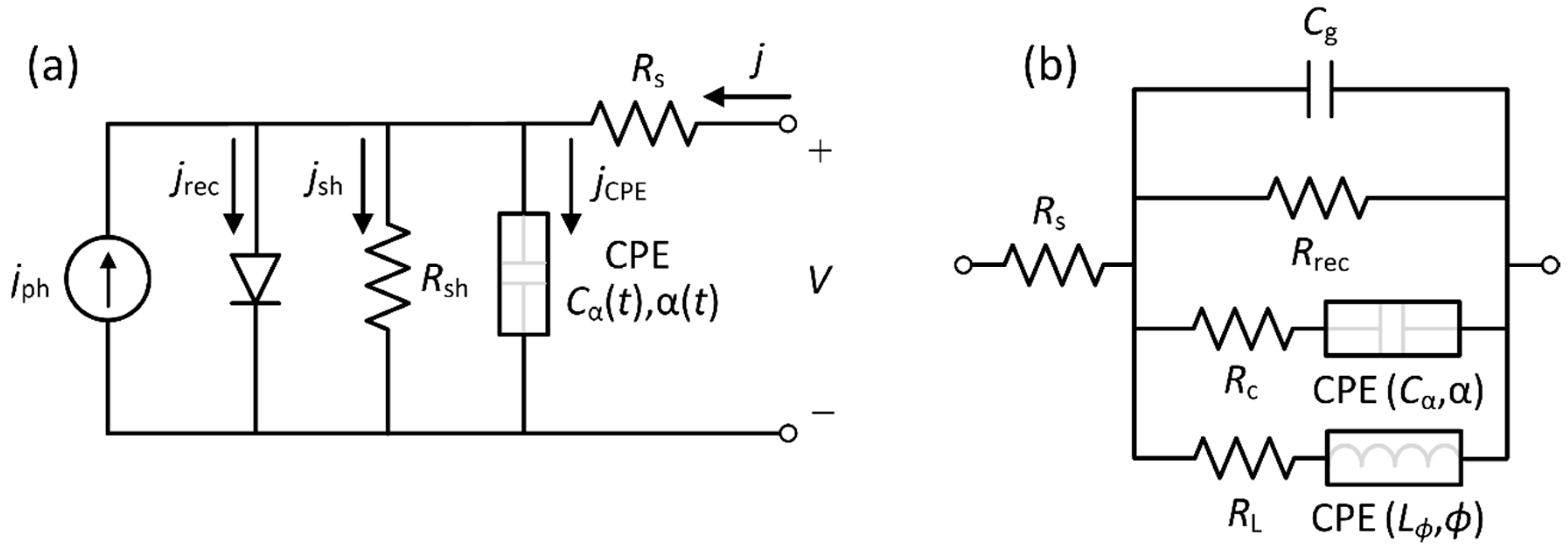
Figure 1. (a) Novel dynamic electrical model for perovskite-based solar cells proposed in this work, where a fractional-order capacitor is introduced by a polarization mechanism. (b) Equivalent circuit representation, valid for impedance interpretation, obtained by applying a small AC modification of a DC steady state.
Fractalfract 07 00516 g001
Figure 2. (a) Dark voltage–current curves of perovskite solar cells under study here performed at different scan rates from 5 to 1000 mV/s. (b) Complex impedance plot measured under dark conditions and at 1 V. The inset of (b) shows the nonideal inductive loop in detail.
Fractalfract 07 00516 g002
Figure 3. (a) Cyclic voltammetry of Cs0.05MA0.15FA0.80Pb1.05(Br0.15I0.85)3 perovskite solar cells measured at 25 mV/s under illumination of 1 Sun. (b,c) Representative impedance evolution from 1 to 1.3 V, concerning the transition from capacitive to inductive effects.
Fractalfract 07 00516 g003
Figure 4. Evolution of time constants and constant-phase element exponents obtained from the impedance parameters throughout the voltage range.
Fractalfract 07 00516 g004
Table 1. Extracted parameters from the fittings of the impedance spectra shown in Figure 3b,c to the equivalent circuit of Figure 1b.
Bias Voltage (V) C g
( µ F · cm 2 )
R rec
( Ω · cm 2 )
R C
( Ω · cm 2 )
C α
( mF · cm 2 · s α 1 )
α R L
( Ω · cm 2 )
L ϕ
( H · cm 2 · s ϕ 1 )
ϕ
10.2833.6323.534.680.62
1.10.278.32142.710.230.68
1.20.323.949.010.730.71
1.30.511.742.240.350.77
Disclaimer/Publisher’s Note: The statements, opinions and data contained in all publications are solely those of the individual author(s) and contributor(s) and not of MDPI and/or the editor(s). MDPI and/or the editor(s) disclaim responsibility for any injury to people or property resulting from any ideas, methods, instructions or products referred to in the content.