Article

Dynamic Feedforward-Based Fractional Order Impedance Control for Robot Manipulator

1
School of Mechanical Science and Engineering, Huazhong University of Science and Technology, Wuhan 430074, China
2
Department of Mechanical Engineering, School of Engineering, University of California, Merced, CA 95343, USA
*
Author to whom correspondence should be addressed.
Fractal Fract. 2023, 7(1), 52; https://doi.org/10.3390/fractalfract7010052
Submission received: 10 September 2022 / Revised: 19 December 2022 / Accepted: 22 December 2022 / Published: 1 January 2023
(This article belongs to the Special Issue Fractional Order Control Techniques for Robots)

Abstract

:
Impedance control is widely applied in contact force control for robot manipulators. The traditional impedance model is linear, and has limitations in describing the actual impedance force. In addition, time-varying and dynamic coupling characteristics pose critical challenges to high-speed and high-precision impedance control. In this paper, a fractional order impedance controller (FOIC) is proposed for industrial robot manipulator control and a systematic FOIC parameters tuning strategy based on frequency-domain specifications is presented. In order to improve performance under dynamic disturbances, a dynamic feedforward-based fractional order impedance controller (DFF-FOIC) is further developed. The robot manipulator dynamics are investigated and the effectiveness of the DFF-FOIC is illustrated by simulation. Then, the DFF-FOIC is applied on a physical robot manipulator prototype. Our step force tracking test results show that the proposed FOIC has better control performance than an integer order impedance controller (IOIC), achieving a better step response with lower overshoot, less settling time, and smaller integral time absolute error (ITAE) than the IOIC under fair comparison conditions.

1. Introduction

Robotic manipulators are widely applied in various fields, including assembly lines [1], spray lacquering [2], and palletizing [3]. In modern manufacturing and human interaction scenes, it is desirable to control the contact force between the robot end and the environment. For example, in the grinding process for complex robotic geometries, the surface machining consistency is hard to guarantee with only trajectory planning control [4]. In robot-assisted needle insertion, the lack of force feedback and control increases tissue deformation and reduces surgeons’ controllability of surgical instruments [5]. Single-position control cannot meet the force perception requirements of these working scenes.
Robot manipulator contact force control has been extensively studied in academic communities and for industrial applications [6]. Position-based impedance control is a common method for robot manipulators [7], based on an outer force control loop and inner position control loop [8]. The traditional mass-spring-damper impedance model is linear, as described in [9]; the integer order model cannot model the impedance force of the physical environment precisely, and the parameter tuning of the impedance controller is limited [10,11]. The fractional order model, with its characteristics of heredity, memory, and nonlinearity, can describe the physical system more accurately [12,13], and is widely used in system modeling and controller design [14,15]. Damping force modeling in viscoelastic dampers was studied in [16]; the results showed that the fractional order derivative-based damper model was more accurate and required fewer parameters compared to the integer model. In [17], a fractional order damping force model based on the fractional Euler–Lagrange equation was proposed to describe the damped oscillating system, and showed better performance than the integer order model. In this paper, a fractional order impedance controller (FOIC) is proposed using a fractional order theory-based damping force model. The fractional order impedance model can describe the contact force more precisely, and FOIC has more tuning parameters and better control performance than IOIC. In addition, a systematic parameter design strategy for FOIC is proposed for optimal controller tuning based on frequency-domain specifications.
In order to further improve the FOIC control performance with high dynamic response requirement, a dynamic feedforward-based fractional order impedance controller (DFF-FOIC) for robot manipulators is proposed. High performance motion is the foundation of machining quality and working efficiency for robot manipulators, and requires high dynamic response and high robustness for controllers [2]. However, robot manipulator dynamics feature high nonlinearity and strong coupling, and are time-variant [18]. The dynamic characteristics have non-negligible effects on motion accuracy, especially in high-magnitude and high-speed motion scenes [19]. Large inertia changes degrade high-speed response, and can lead to system oscillation. In addition, the motion accuracy is affected by system friction [20]. Low machining accuracy and poor lubrication conditions increase the friction significantly [2]. In high speed working scenes, friction seriously affects the desired robot dynamic response and robustness performance [21]. Conventional closed-loop controllers are mainly aimed at the linear constant system; conservative control parameters limit the system gain bandwidth and affect the system’s dynamic response performance [22]. A model-based controller has the ability to reduce nonlinearity for better control performance [23], with a dynamic model feedforward-based controller being an effective method for a robot system to achieve the desired dynamic response and high robustness performance [24]. The DFF-FOIC for robot manipulators proposed in this paper can improve the transient response performance. Accurate dynamic parameters are the foundation of the DFF-FOIC. Dynamic model parameters can be obtained by precise identification methods [25]. In this paper, the Newton–Euler method is used to establish the robot dynamic model [26]. The finite Fourier series is applied as the excitation trajectory to excite the dynamic characteristic for the robot manipulator [27]. The least squares estimator method is used to obtain the identified dynamic parameters [28].
The main contributions of this paper are as follows: (1) A dynamic feedforward-based fractional order impedance controller (DFF-FOIC) for robot manipulators is proposed with optimized impedance modeling accuracy to reduce the impact of robot dynamics with disturbance due to the non-negligible effects of highly nonlinear features, strong coupling, and time variance. (2) The effectiveness of the proposed DFF-FOIC is illustrated in simulation and validated using an industrial robot manipulator experimental platform. The results show that FOIC has better performance than IOIC under the same design specifications. DFF-FOIC can improve the dynamic response and guarantee high robustness performance compared with existing methods.
The rest of this paper is organized as follows: in Section 2, the design of the FOIC and dynamic robot manipulator model are proposed; Section 3 demonstrates the simulation analysis of FOIC and DFF-FOIC and the experimental verification is realized; Section 4 concludes the article.

2. Control Design

2.1. Fractional Calculus and Definitions

The fractional order model is the generalization of the traditional integer order model. The fractional calculus of function f ( t ) is defined as
a D t α f ( t ) = d α d t α f ( t ) , R e ( α ) > 0 f ( t ) , R e ( α ) = 0 a t f ( t ) ( d τ ) α , R e ( α ) < 0 ,
where a D t α is the basic operator of fractional calculus, α is the operator order, a and t are the limits of the fractional order operator, and R e ( α ) represents the real part of α .
Caputo’s definition is one of the most commonly used definitions of fractional derivatives [29]:
0 D t α f ( t ) = 1 Γ ( 1 γ ) 0 t f ( m + 1 ) ( τ ) ( t τ ) γ d τ ,
where α = m + γ , m is an integer, and 0 < γ 1 .

2.2. Design of FOIC

The impedance model consists of a mass, spring, and damper, which dynamically adjust the robot’s posture according to the contact force. The impedance model is shown in Figure 1.
The impedance dynamics equation is
M d x ¨ ( t ) + B d x ˙ ( t ) + K d x ( t ) = F e x t ,
where M d is the mass coefficient, B d is the damper coefficient, K d is the spring coefficient, F e x t is the external force applied to the system, x is the position, and t is the time. The kinematics parameters and external force are dynamically adjusted according to the desired impedance model.
Fractional order theory can be applied to describe the impedance model more accurately than the typical integer order model. In this paper, a fractional order impedance model is proposed with a fractional order damping force model. Thus, Equation (3) can be rewritten as
M d x ¨ ( t ) + B d D t u x ( t ) + K d x ( t ) = F e x t ,
where D t u is the fractional order derivative operator and u ( 0 , 2 ) is the operator order.
The FOIC structure is shown in Figure 2, where B d s u is the fractional order damping force model, u is the operator order, F r e f is the reference contact force, F r e a l is the real force obtained from the force sensor, and F is the error between F r e f and F r e a l ; moreover, X is the desired position adjustment value, X o is the original position of robot manipulator end, X c m d is the final position command, and K s is the spring coefficient of the environment. Due to the high control bandwidth and high control performance of robot manipulator servo systems, the robot position closed loop is represented as 1 to simplify the control system.
The open-loop transfer function is expressed as
G o ( s ) = K s M d s 2 + B d s u + K d .
The closed-loop transfer function is
Φ ( s ) = K s M d s 2 + B d s u + K d + K s .
In a position-based impedance controller, the virtual spring can lead to a steady-state force tracking error [8,30]. Many strategies have been presented to deal with this problem [31,32]. Setting the virtual spring stiffness to 0 is a simple way to eliminate the tracking error [30], and is the approach used in this paper. Setting K d to 0, we have
G o ( s ) = K s M d s 2 + B d s u .
Substituting j ω for s in Equation (7), we have
G o ( j w ) = K s M d ( j w ) 2 + B d ( j w ) u .
An effective controller parameter tuning method is essential for FOIC. Manual tuning is a common method in impedance controller design. As a trial and error strategy, manual tuning is complicated and difficult to implement in different working scenes [33]. Optimization algorithms are another typical method used in designing impedance controllers, although this approach is often time-consuming and unstable [34]. In order to improve the usability of FOIC, a systematic method for tuning parameters based on the frequency domain is proposed. The proposed strategy for tuning the FOIC parameters based on the frequency domain is an analytical method. In this way, the stability of the designed controller can be guaranteed, rather than using test verification as in [34]. In addition, the analytical method is easy to calculate and implement in the robot control system, and does not require a high-performance computer or time-consuming optimization process. The frequency-domain specifications reflect the controller’s fundamental performance, and are easy for engineers to use in different working scenes.
The proposed FOIC tuning method is presented below. Two frequency-domain specifications and one time-domain specification are used, including the gain crossover ω c , phase margin φ m , and integral time square error (ITSE).
(1) Gain crossover
G o ( j w c ) d b = 1 .
(2) Phase margin
A r g [ G o ( j w c ) ] = π + φ m .
The gain and phase of G o ( s ) are as follows:
G o ( j w ) d b = K s [ M d ( j w ) 2 + ( B d p 1 ) ] 2 + ( B d p 2 ) 2 ,
φ ( w ) = arctan B d p 2 M d ( j w ) 2 + B d p 1 .
where
p 1 = w u cos ( π 2 u ) ,
p 2 = w u sin ( π 2 u ) .
Substituting the given gain crossover ω c and the desired phase margin φ m into Equations (9) and (10), we have
M d = K s a ,
B d = b M d .
where
a = [ ( j w c ) 2 + b p 1 ] 2 + ( b p 2 ) 2 ,
b = ( j ω c ) 2 tan ( π φ m ) p 2 p 1 tan ( π φ m ) .
Another time-domain specification ITSE is used to design the FOIC, as follows,
J ITSE = 0 t f t [ e ( t ) ] 2 d t ,
where t f is the final time and e ( t ) is the error between the reference and the actual value corresponding to time t.
The systematic FOIC parameters tuning strategy can be summarized with the following example:
(1) With a gain crossover ω c = 30 rad/s, phase margin φ m = 40 , F r e f = 20 N, and K s = 1293.83 N/m, the real spring stiffness can be identified.
(2) By sweeping u ( 0 , 2 ) , all the controllers satisfying ω c and φ m are calculated according to Equations (13) and (14).
(3) In this step, we implement the step response simulation or the contact force disturbance simulation in steady state of the FOIC considering the desired performance. If tracking performance is mainly being considered, we implement the step response simulation of the FOIC obtained above in (2), then calculate the corresponding J ITSE . If the anti-disturbance performance is mainly being considered, we implement the contact force disturbance simulation of all the FOIC obtained above in (2) in steady state, then calculate the corresponding J ITSE . In the example used here, the tracking performance is mainly being considered, and the step response simulation is implemented.
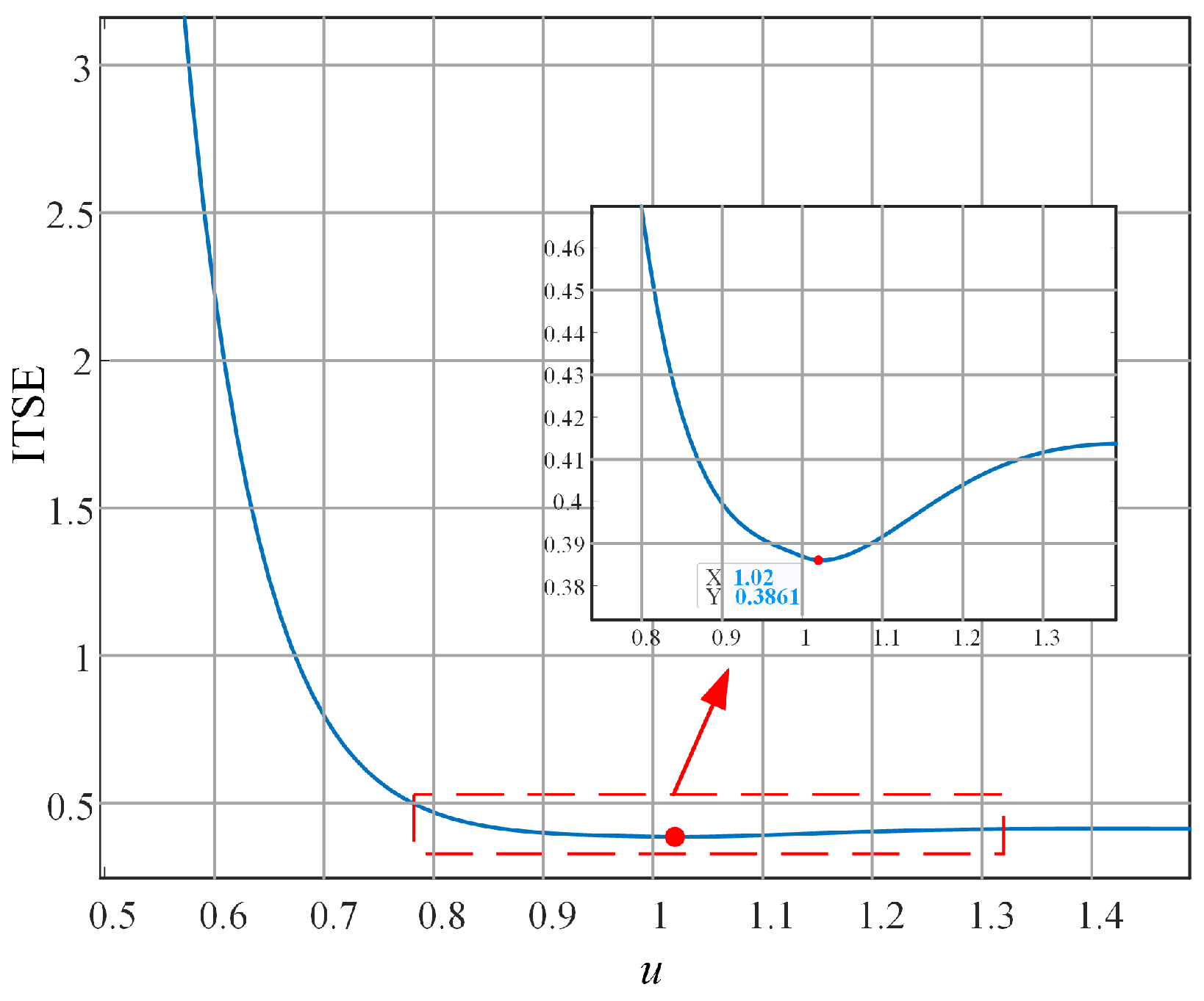
(4) The FOIC according to the smallest J ITSE is selected as the final controller, with M d = 1.0722 kg, B d = 25.9117 N·s/m, and u = 1.02 .
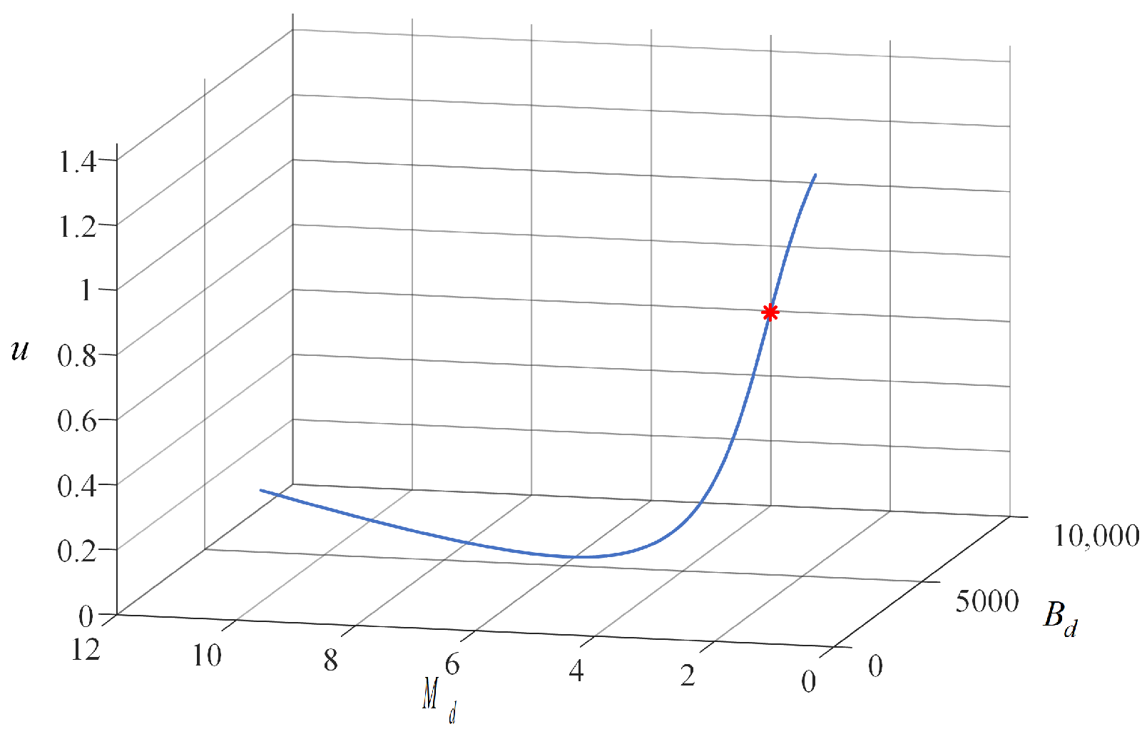
The effects of the control parameters on the performance of the closed-loop system are discussed below. By sweeping u ( 0 , 2 ) , all the controllers satisfying ω c = 30 rad/s for a phase margin φ m = 40 are shown in Figure 3. The performance of FOIC with different control parameters are compared by ITSE. The correspondence diagram between ITSE and u is shown in Figure 4. The red dot in Figure 3 and Figure 4 is the FOIC designed above.

2.3. Stability Analysis

In this subsection, a stability analysis of the FOIC closed-loop system is conducted.
Lemma 1.
An ordinary input/output relation (with only integer derivatives) can be written in a polynomial representation:
P ( σ ) ξ = Q ( σ ) u , y = R ( σ ) ξ ,
where u R m ¯ is the control, ξ R n ¯ is the partial state, and y R p ¯ is the output; here, P, Q and R are polynomial matrices in the variable σ of dimensions n ¯ × n ¯ , n ¯ × m ¯ , and p ¯ × n ¯ , respectively, and σ can be seen as the symbol of the usual derivative s α when all initial conditions are zero.
For a proof of Lemma 1, see [35].
If the triplet (P, Q, R) of polynomial matrices is minimal, we have the following equivalence: System (16) is bounded-input bounded-output iff d e t ( P ( σ ) ) 0 σ , | a r g ( σ ) | < α π / 2 .
Theorem 1.
When choosing appropriate FOIC parameters ( M d , B d , and u) to ensure that
| a r g ( w i ) | > λ π 2 ,
where w i represents the ith root of the equation
M d w 2 q + B d w p + K s = 0 ,
where λ = 1 / q , p / q = u , p, and q are positive integers, then the closed-loop system is bounded, as t .
Proof. 
The structure of FOIC for a robot manipulator is as shown in Figure 2. Due to the high control bandwidth and high control performance of robot manipulator servo systems, the robot’s closed-loop position is represented as 1 to simplify the control system. The transfer function of the force sensor is 1 due to its high performance.
The closed-loop transfer function of FOIC with K d = 0 is
Φ ( s ) = K s M d s 2 + B d s u + K s .
The characteristic equation of Equation (19) is
N ( s ) = M d s 2 + B d s u + K s .
We note that
u = p q , s u = s p / q ,
where p and q are positive integers.
Thus,
N ( s ) = M d s 2 + B d s p / q + K s ,
We denote λ = 1 / q , w = s λ ; then,
N ( w ) = M d w 2 q + B d w p + K s = 0 .
According to Lemma 1, m ˜ = 1, n ˜ = 1, and
| a r g ( w i ) | > λ π 2 ,
therefore, the closed-loop system is bound-input bound-output. □
With the help of Theorem 1, we can state the FOIC considering the robot manipulator system rather than using a gain of 1.
Theorem 2.
When choosing proper FOIC parameters M d , B d , and u to ensure that
| a r g ( w i ) | > λ π 2 ,
where w i represents the ith root of the equation
M d b 2 s 4 + B d b 2 s u + 2 + M d b 1 s 3 + B d b 1 s u + 1 + M d b 0 s 2 + B d b 0 s u + K s a 1 s + K s a 0 = 0 ,
where λ = 1 / q , p / q = u , p, and q are positive integers, M d , B d , are the parameters of FOIC, and a 0 , a 1 , b 0 , b 1 , and b 2 are the parameters of the robot manipulator system, then the closed-loop system is bounded, as t .
Proof. 
The structure of the FOIC for robot manipulator is as shown in Figure 2. The closed-loop transfer function of the FOIC with K d = 0 is
Φ 2 ( s ) = ( a 1 s + a 0 ) K s M d b 2 s 4 + B d b 2 s u + 2 + M d b 1 s 3 + B d b 1 s u + 1 + M d b 0 s 2 + B d b 0 s u + K s a 1 s + K s a 0 .
The characteristic equation of Equation (27) is
N 2 ( s ) = M d b 2 s 4 + B d b 2 s u + 2 + M d b 1 s 3 + B d b 1 s u + 1 + M d b 0 s 2 + B d b 0 s u + K s a 1 s + K s a 0 .
We note that
u = p q , s u = s p / q ,
where p and q are positive integers.
Thus,
N 2 ( s ) = M d b 2 s 4 + B d b 2 s 2 + p / q + M d b 1 s 3 + B d b 1 s 1 + p / q + M d b 0 s 2 + B d b 0 s p / q + K s a 1 s + K s a 0 .
We denote λ = 1 / q , w = s λ ; then,
N 2 ( w ) = M d b 2 w 4 q + B d b 2 w 2 q + p + M d b 1 w 3 q + B d b 1 w q + p + M d b 0 w 2 q + B d b 0 w p + K s a 1 w q + K s a 0 = 0 .
According to Lemma 1, m ˜ = 1, n ˜ = 1, and
| a r g ( w i ) | > λ π 2 ,
therefore, the closed-loop system is bound-input bound-output. □

2.4. Dynamic Model for Robot Manipulator

The disturbance dynamics of robotic manipulators has the characteristics of time variance, high nonlinearity, and strong coupling. These disturbances pose a challenge for the control performance of FOIC with dynamic response and robustness requirements. Dynamic feedforward, as a model-based control strategy, can effectively and fundamentally reduce the influence of robot disturbance dynamics.
The dynamic model for a robot manipulator is as follows:
τ = H ( q ) q ¨ + C ( q , q ˙ ) q ˙ + G ( q ) + F ( q ˙ ) ,
where q, q ˙ , and q ¨ are the vector of joint positions, velocities, and accelerations, respectively, H is the inertia matrix, C is the Coriolis and centripetal coupling matrix, G is the gravity load, F is the friction force, and τ is the vector of actuator forces driving the links. In this paper, the Coulomb viscous friction model is used, as follows:
F = T c + B m q ˙ ,
T c = T c + , q ˙ > 0 0 , q ˙ = 0 T c , q ˙ < 0 ,
where T c and B m are the Coulomb friction and viscous friction coefficients, respectively, and T c + and T c are the different Coulomb friction coefficients corresponding to the rotation of the velocity q ˙ .
Here, τ is linearly related to the dynamic parameters, and Equation (33) can be rewritten as follows [36]:
τ = Y ( q , q ˙ , q ¨ ) P ,
where P = [ P 1 , P 2 , , P j ] (with j being the number of links) is the vector of the dynamic parameters; for link i, P i = [ x x i , x y i , x z i , y y i , y z i , z z i , m x i , m y i , m z i , m i , T c i + , T c i , B m i , J m i ] , where x x i , x y i , x z i , y y i , y z i , z z i are the moments of inertia, m x i , m y i , m z i are the first moment, m i is the link mass, T c i + and T c i are the Coulomb friction coefficients, B m i is the viscous friction coefficient, J m i is the motor inertia, and Y ( q , q ˙ , q ¨ ) is the regressor matrix according to P.
The robot manipulator’s dynamic parameters need to be identified. A standard robot identification process includes model establishment, data acquisition, and data estimation [25]. The dynamics model is linear to P; however, not all of the parameters have effects on the motion [22], which means that Y is not full rank. In order to identify the dynamic parameters, the base parameters-based dynamics model is used for the identification [26]. As for data acquisition, the finite Fourier series excitation trajectories are used to excite the robot dynamics; this approach has the advantages of time-domain data averaging and a specifiable bandwidth of the excitation trajectories [27]. In addition, the velocities and accelerations can be obtained according to the approximated sine and cosine functions of the measured joint position information. Finally, the dynamic parameters are identified as follows:
P = ( Y T Y ) 1 Y T τ ,
where P represents the base parameters, Y is the regressor matrix to P , Y T is the transpose of Y , and τ is the driving force vector of the actuators.
An identification process for the EFORT ERC20C-C10 industrial robot manipulator is presented below.
As mentioned above, the finite Fourier series excitation trajectories are applied for identification, as follows [27]:
q i = l = 1 5 a l , i ω f l sin ( ω f l t ) b l , i ω f l t cos ( w f l t ) + q i 0 ,
where q i is the trajectory of j o i n t i ( i = 1 , 2 , 3 ) , the base frequency w f = 0.2 π , q 10 = 0.1093 , q 20 = 0.1310 , q 30 = 0.0430 , the coefficients a l , i and b l , i are listed in Table 1, and the trajectories are shown in Figure 5.
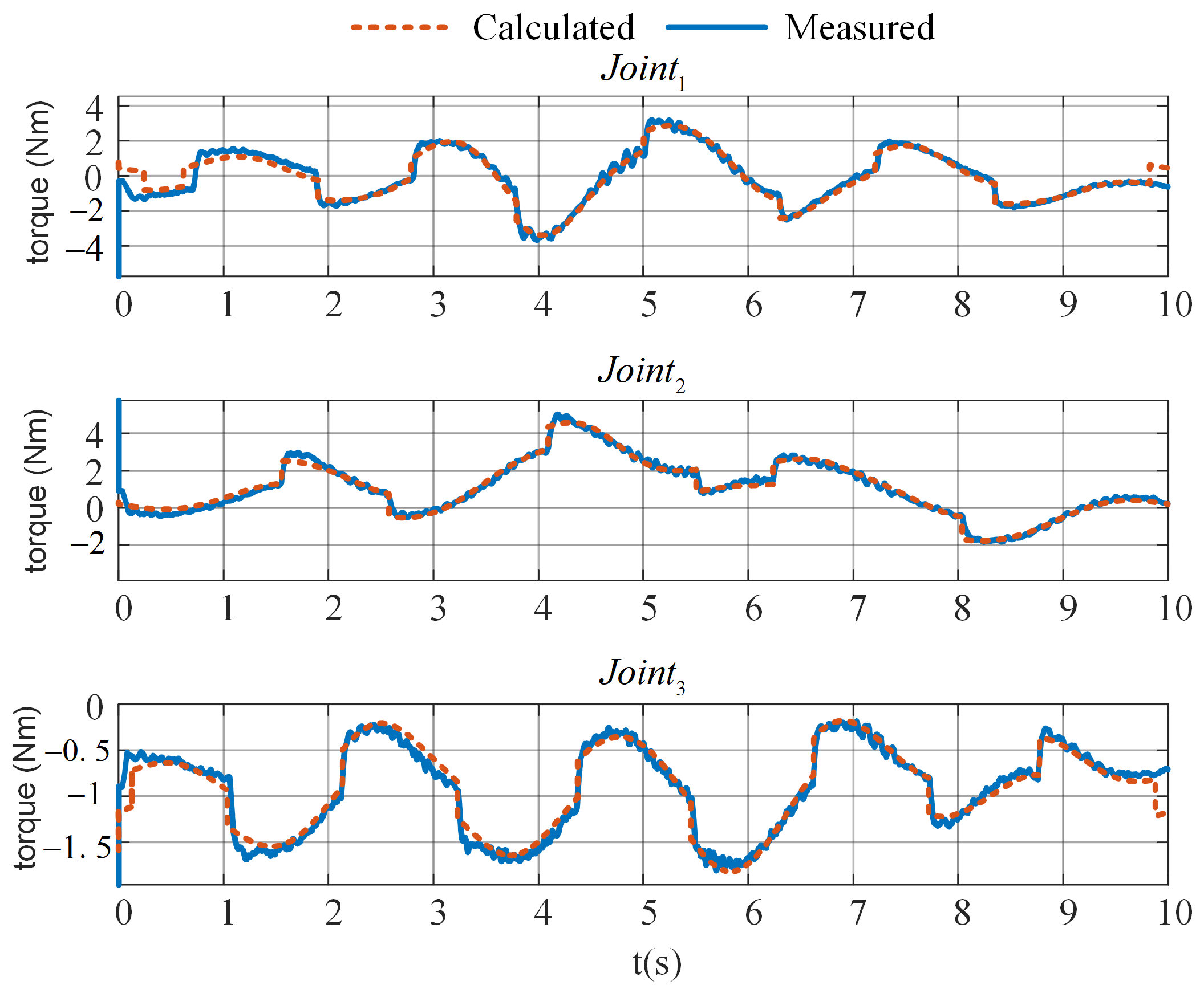
The identified base dynamic parameters of the EFORT ERC20C-C10 are shown in Table 2. The measured and the calculated joint driving torque based on the identified base dynamic parameters of the excitation trajectory are shown in Figure 6. The root mean square errors (RMSE) of the three joints are 0.4223 Nm, 0.3730 Nm, and 0.3162 Nm, respectively, which verifies that the identified dynamic parameters are accurate.

3. Simulation and Experimental Results

3.1. Simulation Illustration

3.1.1. Simulation System

In this section, the construction of an FOIC simulation system for a six degrees of freedom (6DoF) robot manipulator is described. A robot kinematic block and servo block with dynamic disturbance and dynamic feedforward block are designed considering the influence of the robot system and disturbance dynamics, as shown in Figure 7 and Table 3.
The Puma560 6DoF robot manipulator is applied as the robot in simulation. The modified Denavit–Hartenberg (DH) parameters are shown in Table 4. In the impedance test, J o i n t 4 , J o i n t 5 , and J o i n t 6 are without motion; thus, the dynamic parameters of the above joints are all neglected as 0. The dynamic parameters of the Puma560 are listed in Table 5. Considering the reference trajectory and dynamic parameters, we can obtain the required actuator driving forces τ according to Equation (36), which can be used as the dynamic disturbance.

3.1.2. Fractional Order Operator Implementation

The FOIC designed in Section 2 was tested via simulation. The fractional order 1 s u is realized by the impulse response-invariant discretization method [37]. The approximate transfer function order is set as 7 and the sampling frequency is set as 1 KHz. The discretized transfer function of 1 s 1.02 is written as
1 s u = 1 s 1.02 = B ( z 1 ) A ( z 1 ) ,
where:
B ( z 1 ) = 0.8686 z 7 3.592 z 6 + 5.997 z 5 5.146 z 4 + 2.385 z 3 0.5696 z 2 + 0.05899 z 0.001574 and A ( z 1 ) = z 7 4.156 z 6 + 6.978 z 5 6.03 z 4 + 2.82 z 3 0.6817 z 2 + 0.07194 z 0.001998 .
A comparison of the approximated Bode diagram and true Bode diagram is shown in Figure 8. The discretized open-loop Bode plot of the designed FOIC is shown in Figure 9. It can be seen the control system satisfies the given crossover frequency and phase margin specifications.

3.1.3. Step Response Simulation

In this section, the contact force step response simulation for FOIC designed above in Section 2.2 ( ω c = 30 rad/s, φ m = 40 ) is carried out with M d = 1.0722 kg, B d = 25.9117 N·s/m, and u = 1.02 .
The influence of dynamic disturbance is studied and the effectiveness of the dynamic feedforward method is verified. The dynamic characteristics of J o i n t 2 and J o i n t 3 are considered in this part, which are the main motion joints in the simulation. Setting the reference force as 20 N, the following tests are investigated:
(1) Link inertia and gravity
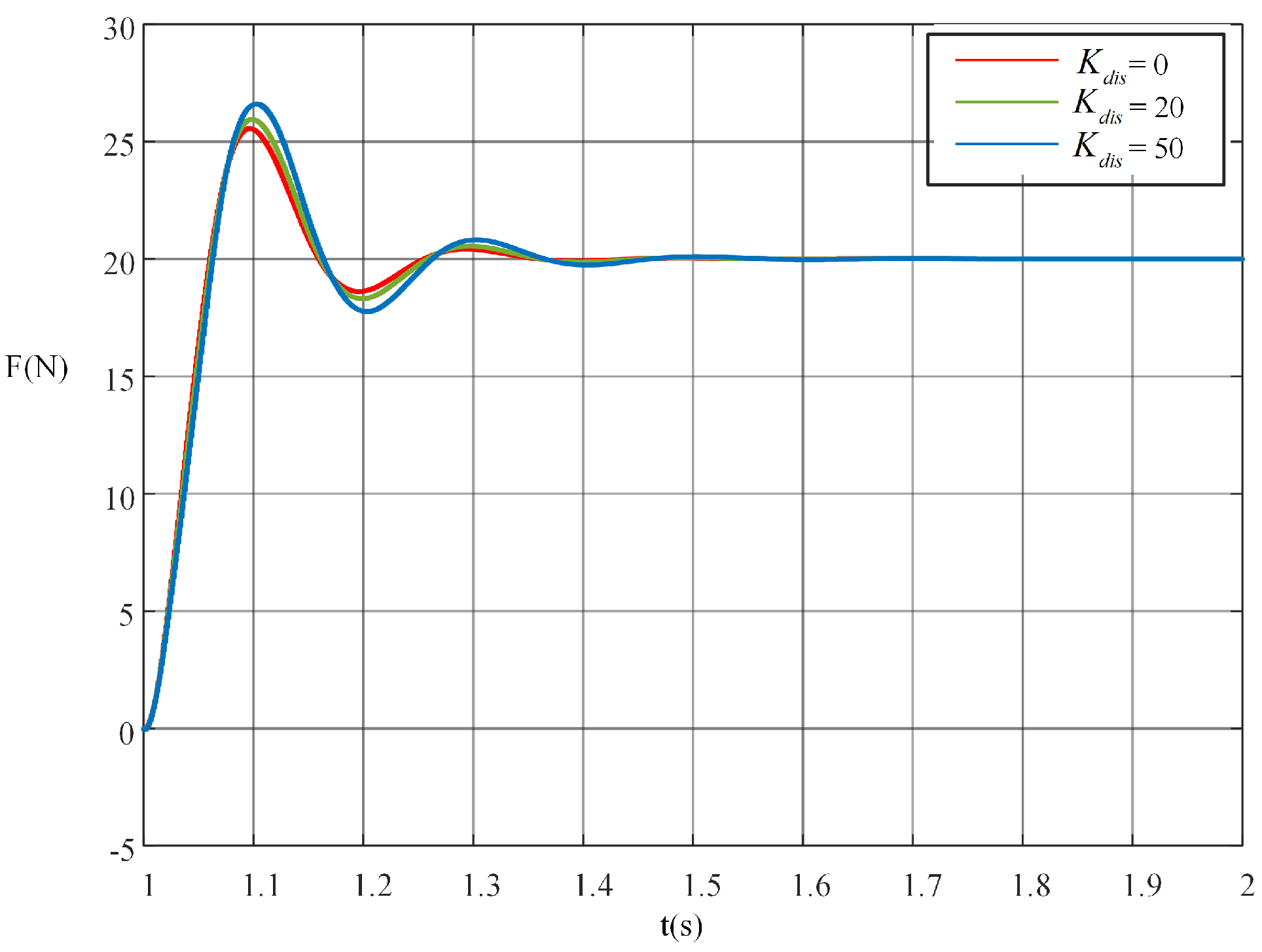
In order to study the influence of link inertia and gravity disturbance, three different disturbance coefficients ( K d i s = 0 , K d i s = 20 , and K d i s = 50 ) in the FOIC were tested. The step response simulation results are shown in Figure 10. As can be seen, link inertia and gravity disturbance increase the overshoot, meaning that the system needs more time to reach steady state.
(2) Friction
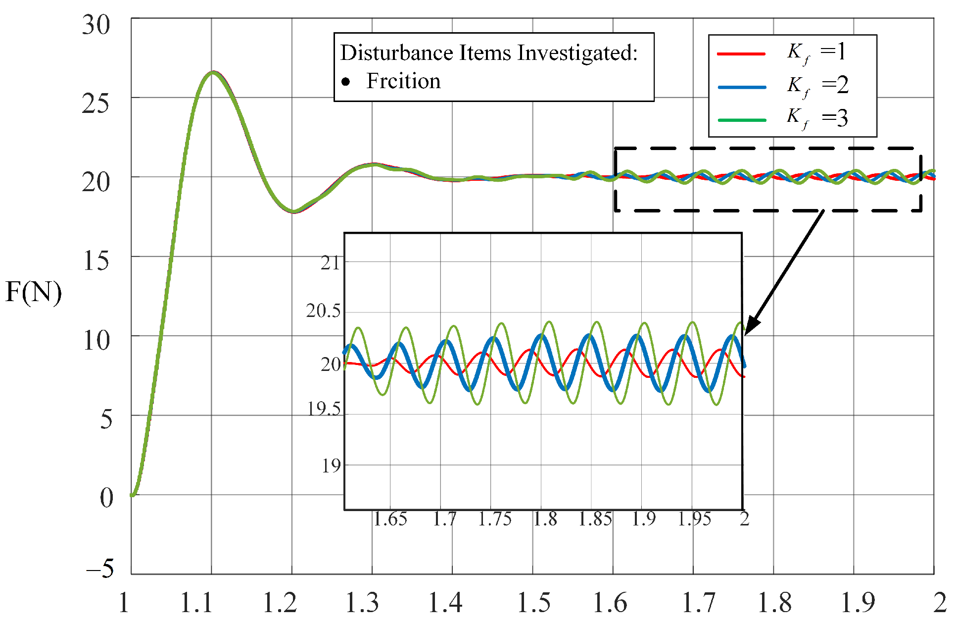
Coulomb Friction disturbance is considered in this part. In order to better investigate the effectiveness of the friction disturbance, the disturbance coefficient is set as K d i s = 20 , as above, and the Coulomb friction coefficient T c of J o i n t 2 and J o i n t 3 is adjusted. Here, K f is used as the amplification coefficient for T c . In this way, the influence of friction disturbance is investigated alone without any impact from changing the link inertia and gravity. The response curves of the contact force with three different T c amplification coefficients, K f = 1 , K f = 2 , and K f = 3 , are shown in Figure 11. The results clearly indicate that Coulomb friction disturbance can induce contact force variations. When friction is stronger, the contact force fluctuation is larger.
(3) Link inertia, gravity, and friction.
For further validation, all the dynamic impact factors, that is, link inertia, gravity, and friction, were taken into account together. The friction parameters in Table 5 were used. The force tracking performances were compared under three different disturbance coefficients K d i s = 0 , K d i s = 20 , K d i s = 50 . The response curves of the system output are presented in Figure 12. The results show the combined characteristics of the previous two items. As the growth in the disturbance coefficient increases, the system has a worse response speed, larger overshoot, longer settling time, and larger force fluctuation.
To verify the effectiveness of the dynamic feedforward method, the dynamic parameters in Table 5 were used. Dynamic disturbance with coefficient K d i s = 20 was applied for the test. Three different levels of compensation simulation with feedforward coefficients of K f f = 0 , K f f = 2.5 , and K f f = 5 are presented in Figure 13. The results show that dynamic feedforward can effectively suppress the dynamic disturbance. The controller with dynamic feedforward achieves a better response speed, can suppress the overshoot caused by dynamic disturbance, and has a shorter settling time and better robustness performance compared with the controller without dynamic feedforward.

3.2. Experimental Verification

3.2.1. Experimental Setup

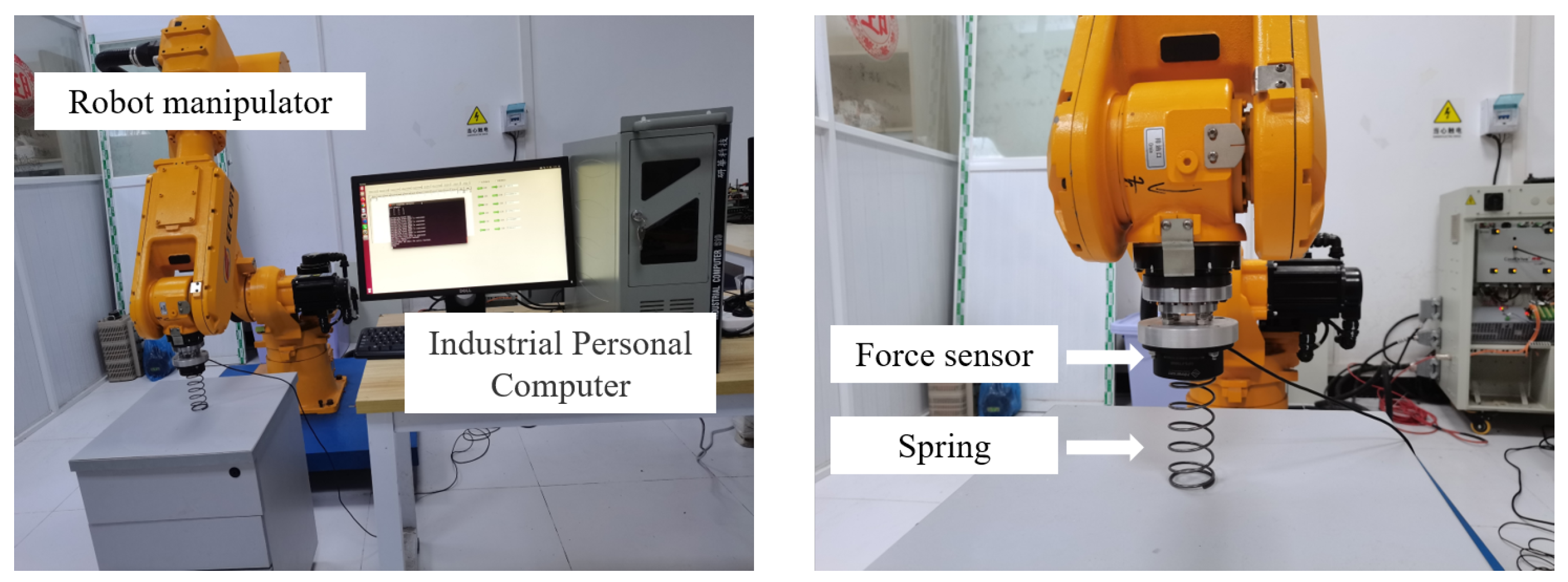
This section describes the experiments we carried out. The experimental setup consisted of a 6DoF EFORT ER20C-C10 industrial robot manipulator, an ADVANTECH industrial computer with a self-developed robot controller and self-developed human–computer interface software, a 6DoF HPS-FT060E force sensor, and a spring, as shown in Figure 14. Communication between the equipment used EtherCAT. An Igh-EtherCAT master stack was embedded in the self-developed robot controller to communicate with other EtherCAT slaves, including the servo system and the force sensor. The communication update frequency was set as 1 KHz. The detailed experimental setup information is shown in Table 6. The modified DH parameters for robot manipulator are listed in Table 7. The identified base dynamic parameters are shown in Table 2. In TSINO DYNATRON CoolDrive R6, the object dictionary data index 60B2 h of EtherCAT, described as the torque offset, is used as the dynamic feedforward torque transmission interface from the Igh-EtherCAT master stack in the self-developed controller to the EtherCAT slaves. The torque offset index 60B2 h is a common object data index in CiA402, which means that the proposed dynamic feedforward strategy can be applied in many other servo systems based on EtherCAT communication.

3.2.2. Experimental Tests

To validate the effectiveness of the proposed FOIC and DFF-FOIC, experiments were carried out as described in this section.
(1) FOIC and IOIC comparison
In this section, the design of the FOIC is investigated considering the tracking performance and the anti-disturbance performance.
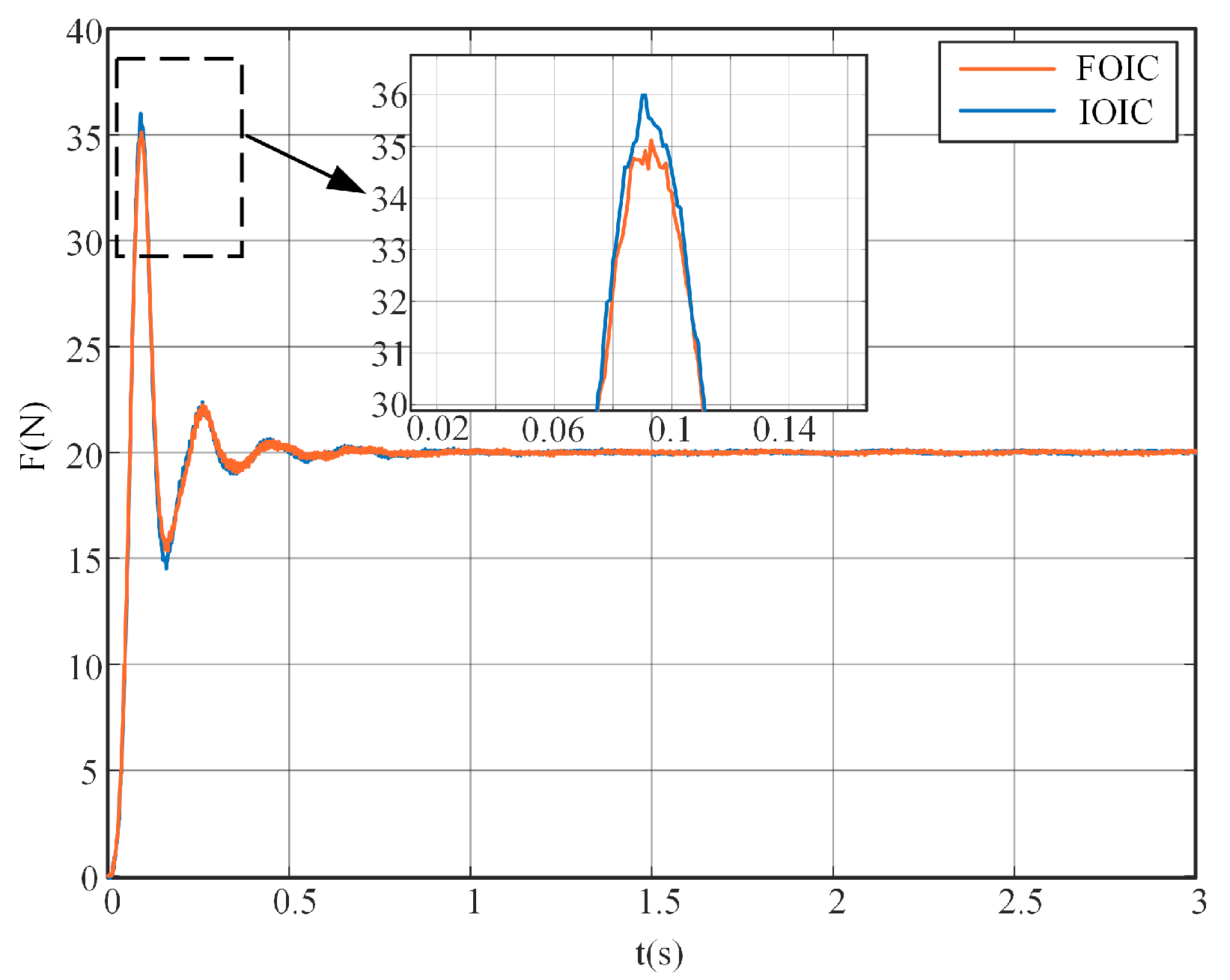
First, the FOIC was designed mainly considering the tracking performance and compared with the IOIC under the same frequency domain. The FOIC and IOIC were designed and compared under the same frequency-domain specifications for fair comparison of ω c = 30 rad/s and φ m = 40 . The parameters of the IOIC were designed according to Equations (13) and (14), with u = 1 , for which the results are M d = 1.1013 kg and B d = 27.7219 N·s/m. The force step tracking curves are shown in Figure 15. The implemented experiments were repeated ten times. The average performance comparisons are shown in Table 8. The results show that the FOIC has faster response speed, smaller overshoot, and less settling time than IOIC.
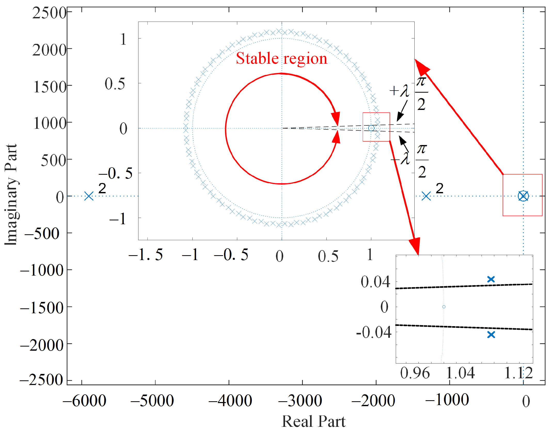
The stability of the designed FOIC is proven as follows. Entering the parameters into Equation (18), we choose u = 1.02 , λ = 1 / q = 0.02 , w = s λ = s 0.02 , q = 50 , and p = 51 ; the pole plot is shown in Figure 16. The slopes of the two stable region boundaries are ± λ π 2 , corresponding to ± π 2 for the integer order system. Thus, the system should be BIBO-stable according to the stability analysis in Section 2.3.
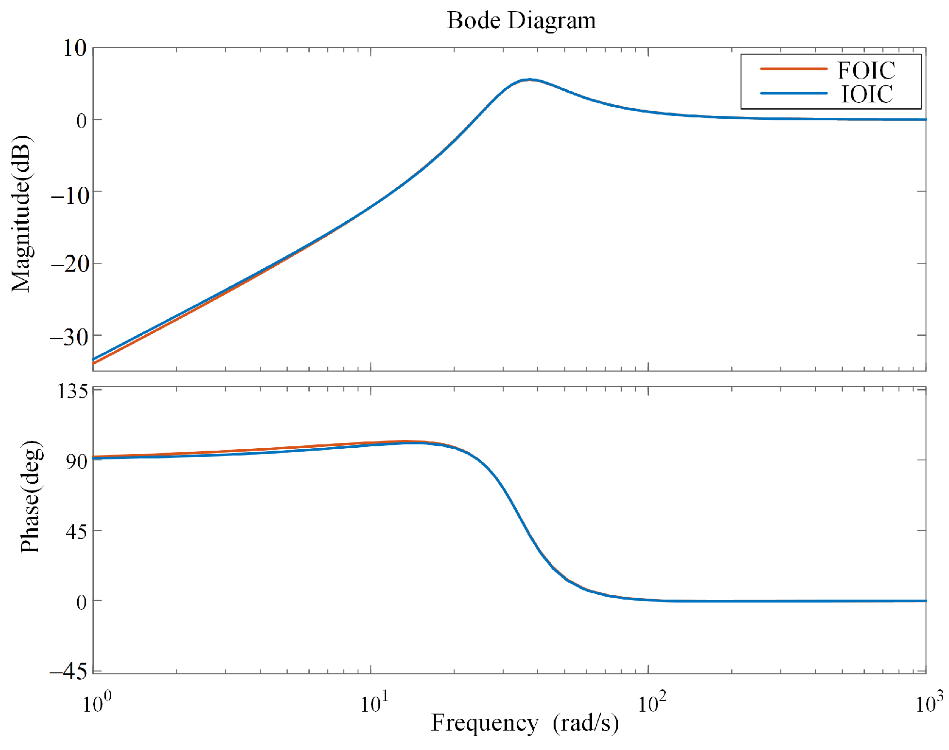
Second, the FOIC was designed considering anti-disturbance performance and compared with IOIC under the same frequency domain of ω c = 30 rad/s and phase margin φ m = 40 . The design process was as described in Section 2.2; a contact force disturbance of 3 N was added in steady state during the design process of the FOIC. With the influence of force disturbance, the contact force dropped off and then quickly reached steady state at the given reference contact force. The final designed FOIC with the smallest J ITSE was M d = 1.0722 kg and B d = 25.9117 N·s/m, and u = 1.02 , while the IOIC was M d = 1.1013 kg and B d = 27.7219 N·s/m. The average performance results for ten repetitions of the anti-disturbance experiment are listed in Table 9. The Bode sensitivity plots for FOIC and IOIC are shown in Figure 17; it can be seen that FOIC has better ability to reject disturbances compared to IOIC.
The stability of the closed-loop system under the effects of disturbances was addressed by identifying the robot manipulator system of the EFORT ER20C-10, including the inverse kinematics, servos of the joints, and forward kinematics, using the obtained experimental data. The inverse and forward kinematic were described linearly due to the small range of motion in the experiment. The servos of the joints were modeled by first-order systems. The transfer function of the robot manipulator in the impedance control experiment is as follows:
G r ( s ) = a 1 s + a 0 b 2 s 2 + b 1 s + b 0 ,
where a 1 = 5170.733366 , a 0 = 7.779515177 × 10 6 , b 2 = 1 , b 1 = 7223.609339 , and b 0 = 7.790596290 × 10 6 .
See Appendix A for the detailed identification.
The closed-loop transfer function of FOIC considering the robot manipulator system is
Φ 2 ( s ) = ( a 1 s + a 0 ) K s M d b 2 s 4 + B d b 2 s u + 2 + M d b 1 s 3 + B d b 1 s u + 1 + M d b 0 s 2 + B d b 0 s u + K s a 1 s + K s a 0 .
The stability of the designed FOIC robot manipulator is proven as follows. Entering the parameters into Equation (26), we choose u = 1.02 , λ = 1 / q = 0.02 , w = s λ = s 0.02 , q = 50 , and p = 51 ; the pole plot is shown in Figure 18. The slopes of the two stable region boundaries for the integer order system are ± λ π 2 . The minimum argument of the root is 0.0391 rad, and the argument of the stability bound is 0.0314 rad; thus, the system should be BIBO stable.
(2) FOIC and DFF-FOIC comparison
Although FOIC achieved better control performance than IOIC, FOIC can be further improved by DFF-FOIC.
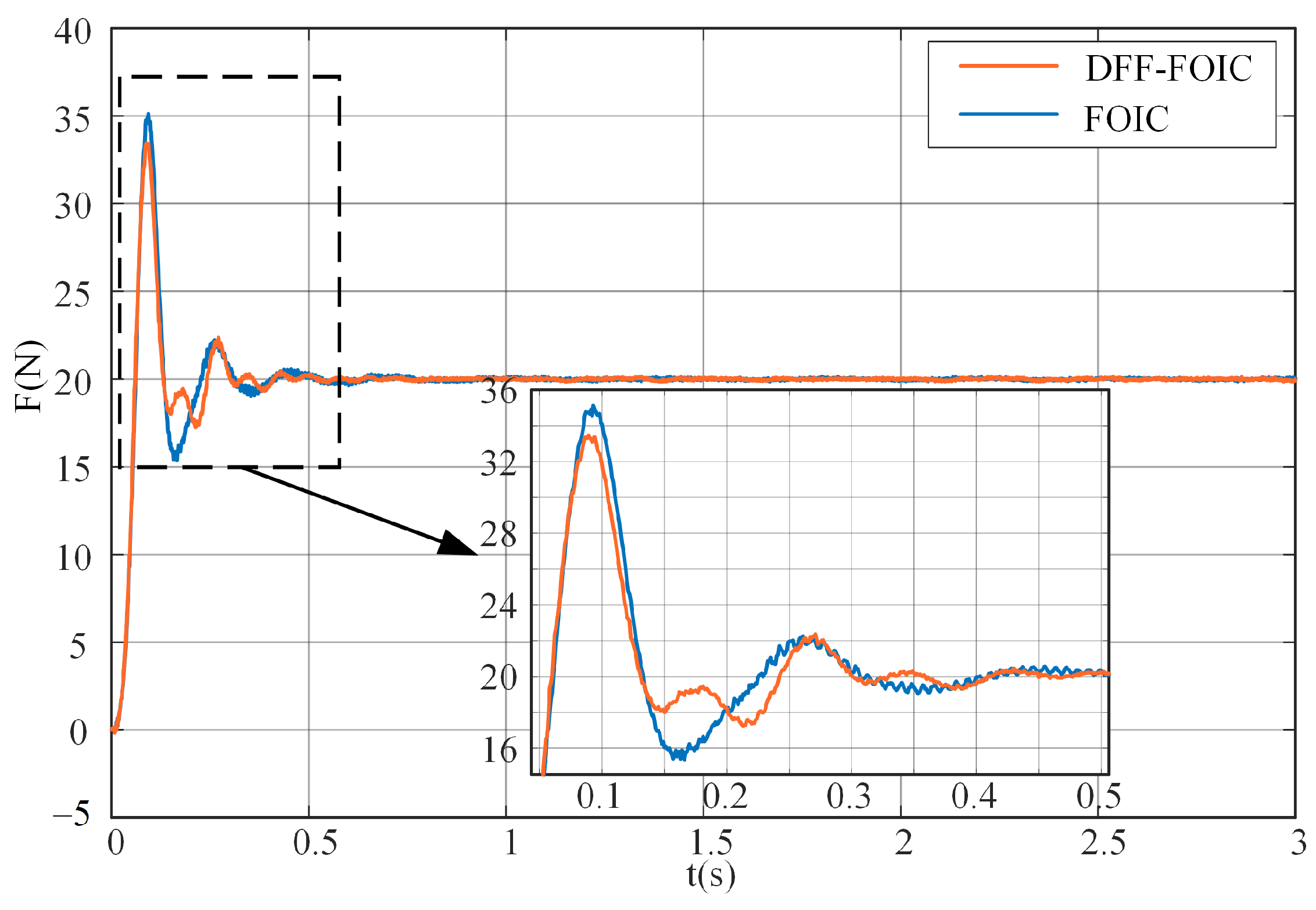
The dynamic feedforward method was verified to improve the performance of FOIC with M d = 1.0722 kg, B d = 25.9117 N·s/m, and u = 1.02 . The robot manipulator is severely affected by dynamic disturbances during motion. The step force tracking results are shown in Figure 19, and the experimental performance indexes are listed in Table 10. These results demonstrate that the robot with dynamic feedforward can effectively suppress dynamic disturbances and improve the performance of FOIC.
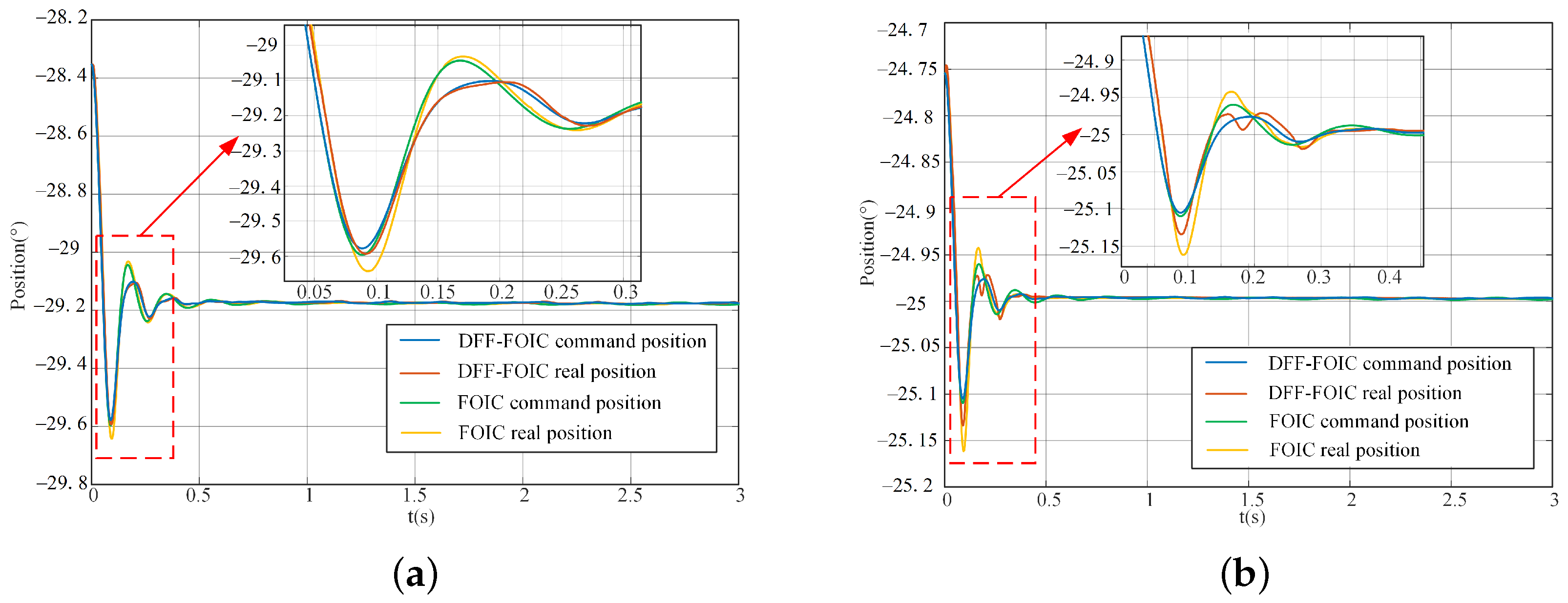
With dynamic feedforward, the rising time is improved by 16.39%, the overshoot is reduced by 10.96%, and the settling time is reduced by 9.07%. In addition, DFF-FOIC has better ITAE than FOIC by 12.41%. The tracking performance of the servo systems is improved, as shown in Figure 20. As for J o i n t 2 and J o i n t 3 , ITAE is improved by 44.44% and 37.5%, respectively, as shown in Table 11.
(3) DFF-FOIC robustness study
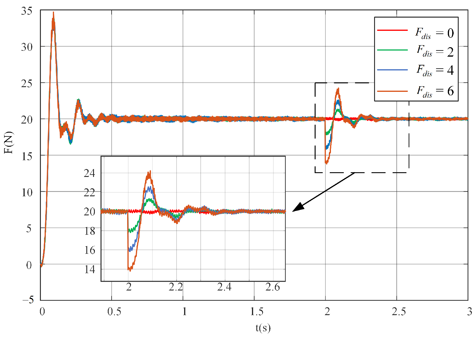
The robustness of the robot manipulator system from (2) above was examined under DFF-FOIC. Different contact force disturbances were added to the system by setting a virtual force disturbance parameter in the control system, with F d i s = 0 N, F d i s = 2 N, F d i s = 4 N, and F d i s = 6 N. The results show that the proposed DFF-FOIC can maintain a stable state even under influence from force disturbances, and can achieve the desired robustness performance, as shown in Figure 21.
(4) Performance comparison with NSGA-IC
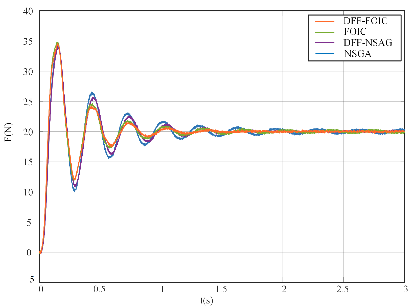
In this part, the proposed controller is compared with a state-of-art impedance control scheme, the non-dominated sorting genetic algorithm II-based impedance controller (NSGA-IC) [34]. The integer order impedance control parameters of NSGA-IC are designed by a multi-objective genetic algorithm NSGA-II. In this part, a comparison between the proposed FOIC and the NSGA-IC is carried out. In order to further illustrate the effectiveness of the dynamic feedforward method, DFF-FOIC is compared with dynamic feedforward-based NSGA-IC (DFF-NSGA-IC).
First, the NSGA-IC is designed as follows. The impedance model is as shown in Equation (3). The rise time ( T r ), total variation ( T v ), and steady state error ( E s s ) are chosen as the optimization metrics, with K d set as 0 to eliminate the steady state error. The optimization problem is presented in Equation (42):
m i n x ( T v , T r , E s s ) X = [ M d , B d ] T s . t . 0 M d 100 K g 0 B d 100 N · s / m
Generations and individuals in NSGA-IC were set as 20 and 20, respectively. The designed parameters of NSGA-IC are M d = 2.9871 kg and B d = 25.2114 N·s/m.
The frequency-domain specifications of the optimized NSGA-IC are gain crossover ω c = 20 rad/s and phase margin φ m = 22 . 9 . In order to compare the performance of FOIC and NSGA-IC fairly, the FOIC was designed with the same frequency specifications as NSGA-IC, that is, M d = 0.7730 kg, B d = 6.8271 N·s/m, and u = 1.67 . The results show that the proposed FOIC achieves better response speed, a lower settling time, and better ITSE than NSGA-IC. In order to illustrate the performance of the dynamic feedforward method, dynamic feedforward-based NSGA-IC(DFF-NSGA-IC) was implemented. The experimental results show that DFF-NSGA-IC has better control performance than NSGA-IC, which verifies the performance of the dynamic feedforward method. DFF-FOIC can achieve better response performance and robustness performance than DFF-NSGA-IC. Furthermore, the controller design process of NSGA-IC takes a much longer time than the method proposed in this paper for tuning the parameters of FOIC. The comparisons are shown in Figure 22 and Table 12.

4. Conclusions

In this paper, an FOIC is proposed to achieve better contact force control performanc of robot manipulatorse than IOIC. A systematic parameter tuning method is presented based on frequency-domain specifications. The impact of dynamic disturbances on robot manipulators is investigated. DFF-FOIC is proposed to further improve the performance of FOIC in high-speed response working scenes. The effectiveness of the proposed DFF-FOIC is verified via both simulations and experiments. Our results show that DFF-FOIC can effectively suppress dynamic disturbance impacts in a robot manipulator and achieve the desired control performance.

Author Contributions

Conceptualization, Y.L.; Methodology, Y.D. and Y.L.; Investigation, Y.D.; Data curation, Y.D.; Writing—original draft, Y.D.; Writing—review & editing, Y.L. and Y.C. All authors have read and agreed to the published version of the manuscript.

Funding

This work was supported by the National Natural Science Foundation of China [51975234].

Data Availability Statement

Not applicable.

Conflicts of Interest

The authors declare no conflict of interest.

Appendix A. Identification of Robot Manipulator System
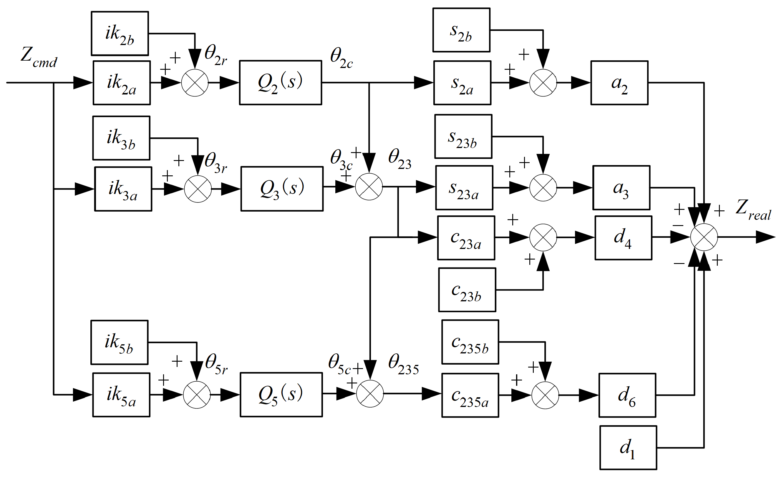
The model of the robot manipulator system shown in Figure 7 is identified according to the collected experimental data of FOIC with ω c = 30 rad/s and φ m = 40 , including the inverse kinematic, servos of joints, and forward kinematics. The inverse kinematics process is used to obtain the desired joint position according to the robot end command in Cartesian space. The forward kinematics process is used to calculate the position of the robot end in Cartesian space according to the joint positions.
In the FOIC experiment for the EFORT ER20C-10, only the contact force in the Z axis in the Cartesian space is moved, with a motion of 2 cm; j o i n t 2 , j o i n t 3 , and j o i n g 5 are used with only a small motion range. Thus, the relationship between the command in the Z axis in Cartesian space and the joint position can be linear. The identification results of inverse kinematic are as follows:
θ 2 ( t ) i k 2 ( t ) = i k 2 a Z ( t ) + i k 2 b , θ 3 ( t ) i k 3 ( t ) = i k 3 a Z ( t ) + i k 3 b , θ 5 ( t ) i k 5 ( t ) = i k 5 a Z ( t ) + i k 5 b .
where Z ( t ) is a command in the Z axis in Cartesian space, θ i ( t ) ( i = 1 , 2 6 ) is the joint position, i k 2 a = 8.955 × 10 4 , i k 2 b = 0.5896 , i k 3 a = 2.8210 × 10 4 , i k 3 b = 0.5850 , i k 5 a = 0.0012 , and i k 5 b = 0.0118 .
The model of the servos is described by the first-order system. The identified results are as follows:
Q 2 ( s ) = 1 1.694 × 10 4 s + 0.9999 , Q 3 ( s ) = 1 7.5819 × 10 4 s + 1.0000 , Q 5 ( s ) = 1 1.6746 × 10 4 s + 1.0000 .
where Q i ( s ) ( i = 2 , 3 , 5 ) is the transfer function of servo of j o i n t i .
The model of the forward kinematics is linear within the defined motion range. The expression of the forward kinematics of the EFORT ERC20C-10 is as follows, with θ 1 = 0 rad, θ 4 = 0 rad, and θ 6 = 0 rad:
Z ( t ) = d 1 d 6 cos ( θ 2 ( t ) + θ 3 ( t ) + θ 5 ( t ) ) d 4 cos ( θ 2 ( t ) + θ 3 ( t ) ) + a 3 sin ( θ 2 ( t ) + θ 3 ( t ) ) + a 2 sin ( θ 2 ( t ) ) ,
where Z ( t ) is a command in the Z axis in Cartesian space, d 1 , d 4 , d 6 , a 2 , a 3 are the DH parameters for ERC20-C10 as seen in Table 7, and θ i ( t ) ( i = 1 , 2 6 ) is the joint position. The nonlinear items sin ( θ 2 ( t ) ) , cos ( θ 2 ( t ) + θ 3 ( t ) ) , sin ( θ 2 ( t ) + θ 3 ( t ) ) , and cos ( θ 2 ( t ) + θ 3 ( t ) + θ 5 ( t ) ) can be described linearly due to the small motion range of θ i ( t ) ( i = 1 , 2 6 ) . The identified results are as follows:
sin ( θ 2 ( t ) ) s 2 ( t ) = s 2 a θ 2 ( t ) + s 2 b , sin ( θ 2 ( t ) + θ 3 ( t ) ) s 23 ( t ) = s 23 a ( θ 2 ( t ) + θ 3 ( t ) ) + s 23 b , cos ( θ 2 ( t ) + θ 3 ( t ) ) c 23 ( t ) = c 23 a ( θ 2 ( t ) + θ 3 ( t ) ) + c 23 b , cos ( θ 2 ( t ) + θ 3 ( t ) + θ 5 ( t ) ) c 235 ( t ) = c 235 a ( θ 2 ( t ) + θ 3 ( t ) + θ 5 ( t ) ) + c 235 b .
where s 2 a = 0.4842 , s 2 b = 0.3591 , s 23 a = 0.8081 , s 23 b = 0.0800 , c 23 a = 0.5890 , c 23 b = 1.1791 , c 235 a = 0.000 , and c 235 b = 1 .
The identified robot manipulator system structure is shown in Figure A1.
Figure A1. The structure of the identified robot manipulator system.
Fractalfract 07 00052 g0a1
where θ i r and θ i c ( i = 2 , 3 , 5 ) are the desired and the real positions of j o i n t i , respectively, θ 23 is the sum position of θ 2 and θ 3 , and θ 235 is the sum position of θ 2 , θ 3 , and θ 5 .
According to the above results, the derived transfer function of the robot manipulator system in the impedance control experiment is as follows:
G r ( s ) = a 1 s + a 0 b 2 s 2 + b 1 s + b 0
where a 1 = 5170.733366 , a 0 = 7.779515177 × 10 6 , b 2 = 1 , b 1 = 7223.609339 , and b 0 = 7.790596290 × 10 6 .

References

  1. Xu, J.; Zhang, C.; Liu, Z.; Pei, Y. A review on significant technologies related to the robot-guided intelligent bolt assembly under complex or uncertain working conditions. IEEE Access 2019, 7, 136752–136776. [Google Scholar] [CrossRef]
  2. Zhang, B.; Wu, J.; Wang, L.; Yu, Z. Accurate dynamic modeling and control parameters design of an industrial hybrid spray-painting robot. Robot. Comput.-Integr. Manuf. 2020, 63, 101923. [Google Scholar] [CrossRef]
  3. He, Y.; Mei, J.; Fang, Z.; Zhang, F.; Zhao, Y. Minimum energy trajectory optimization for driving systems of palletizing robot joints. Math. Probl. Eng. 2018, 2018, 7247093. [Google Scholar] [CrossRef] [Green Version]
  4. Zhu, D.; Feng, X.; Xu, X.; Yang, Z.; Li, W.; Yan, S.; Ding, H. Robotic grinding of complex components: A step towards efficient and intelligent machining–challenges, solutions, and applications. Robot. Comput.-Integr. Manuf. 2020, 65, 101908. [Google Scholar] [CrossRef]
  5. Yang, C.; Xie, Y.; Liu, S.; Sun, D. Force modeling, identification, and feedback control of robot-assisted needle insertion: A survey of the literature. Sensors 2018, 18, 561. [Google Scholar] [CrossRef] [PubMed] [Green Version]
  6. Zeng, G.; Hemami, A. An overview of robot force control. Robotica 1997, 15, 473–482. [Google Scholar] [CrossRef]
  7. Hogan, N. Impedance Control: An Approach to Manipulation: Part II—Implementation. J. Dyn. Syst. Meas. Control 1985, 107, 8–16. [Google Scholar] [CrossRef]
  8. Al-Shuka, H.F.; Leonhardt, S.; Zhu, W.H.; Song, R.; Ding, C.; Li, Y. Active impedance control of bioinspired motion robotic manipulators: An overview. Appl. Bionics Biomech. 2018, 2018, 8203054. [Google Scholar] [CrossRef] [PubMed]
  9. Hogan, N. Impedance control: An approach to manipulation. In Proceedings of the 1984 American Control Conference, San Diego, CA, USA, 6–8 June 1984; pp. 304–313. [Google Scholar]
  10. Schmidt, A.; Gaul, L. On a critique of a numerical scheme for the calculation of fractionally damped dynamical systems. Mech. Res. Commun. 2006, 33, 99–107. [Google Scholar] [CrossRef]
  11. Kobayashi, Y.; Onishi, A.; Hoshi, T.; Kawamura, K.; Hashizume, M.; Fujie, M.G. Validation of viscoelastic and nonlinear liver model for needle insertion from in vivo experiments. In Proceedings of the International Workshop on Medical Imaging and Virtual Reality, Tokyo, Japan, 1–2 August 2008; pp. 50–59. [Google Scholar]
  12. Sun, H.; Zhang, Y.; Baleanu, D.; Chen, W.; Chen, Y. A new collection of real world applications of fractional calculus in science and engineering. Commun. Nonlinear Sci. Numer. Simul. 2018, 64, 213–231. [Google Scholar] [CrossRef]
  13. Niu, H.; Chen, Y.; West, B.J. Why do big data and machine learning entail the fractional dynamics? Entropy 2021, 23, 297. [Google Scholar] [CrossRef]
  14. Chen, P.; Luo, Y. A Two-Degree-of-Freedom Controller Design Satisfying Separation Principle With Fractional-Order PD and Generalized ESO. IEEE/ASME Trans. Mechatronics 2021, 27, 137–148. [Google Scholar] [CrossRef]
  15. Luo, Y.; Zhang, T.; Lee, B.; Kang, C.; Chen, Y. Fractional-order proportional derivative controller synthesis and implementation for hard-disk-drive servo system. IEEE Trans. Control Syst. Technol. 2013, 22, 281–289. [Google Scholar] [CrossRef] [Green Version]
  16. Dadkhah Khiabani, E.; Ghaffarzadeh, H.; Shiri, B.; Katebi, J. Spline collocation methods for seismic analysis of multiple degree of freedom systems with visco-elastic dampers using fractional models. J. Vib. Control 2020, 26, 1445–1462. [Google Scholar] [CrossRef]
  17. Agila, A.; Baleanu, D.; Eid, R.; Irfanoglu, B. A freely damped oscillating fractional dynamic system modeled by fractional Euler–Lagrange equations. J. Vib. Control 2018, 24, 1228–1238. [Google Scholar] [CrossRef]
  18. Yang, C.; Jiang, Y.; He, W.; Na, J.; Li, Z.; Xu, B. Adaptive parameter estimation and control design for robot manipulators with finite-time convergence. IEEE Trans. Ind. Electron. 2018, 65, 8112–8123. [Google Scholar] [CrossRef]
  19. Zhang, B.; Wu, J.; Wang, L.; Yu, Z.; Fu, P. A method to realize accurate dynamic feedforward control of a spray-painting robot for airplane wings. IEEE/ASME Trans. Mechatronics 2018, 23, 1182–1192. [Google Scholar] [CrossRef]
  20. Hui, J.; Pan, M.; Zhao, R.; Luo, L.; Wu, L. The closed-form motion equation of redundant actuation parallel robot with joint friction: An application of the Udwadia–Kalaba approach. Nonlinear Dyn. 2018, 93, 689–703. [Google Scholar] [CrossRef]
  21. Yao, J.; Deng, W.; Jiao, Z. Adaptive control of hydraulic actuators with LuGre model-based friction compensation. IEEE Trans. Ind. Electron. 2015, 62, 6469–6477. [Google Scholar] [CrossRef]
  22. Wu, J.; Li, W.; Xiong, Z. Identification of robot dynamic model and joint frictions using a baseplate force sensor. Sci. China Technol. Sci. 2022, 65, 30–40. [Google Scholar] [CrossRef]
  23. Xie, Z.; Xie, F.; Liu, X.J.; Wang, J.; Mei, B. Tracking error prediction informed motion control of a parallel machine tool for high-performance machining. Int. J. Mach. Tools Manuf. 2021, 164, 103714. [Google Scholar] [CrossRef]
  24. Liu, L.; Tian, S.; Xue, D.; Zhang, T.; Chen, Y. Industrial feedforward control technology: A review. J. Intell. Manuf. 2019, 30, 2819–2833. [Google Scholar] [CrossRef]
  25. Wu, J.; Wang, J.; You, Z. An overview of dynamic parameter identification of robots. Robot. Comput.-Integr. Manuf. 2010, 26, 414–419. [Google Scholar] [CrossRef]
  26. Huo, W. New formulas for complete determining base parameters of robots. In Proceedings of the 1995 IEEE International Conference on Robotics and Automation, Nagoya, Japan, 21–27 May 1995; Volume 3, pp. 3021–3026. [Google Scholar]
  27. Swevers, J.; Ganseman, C.; Tukel, D.B.; De Schutter, J.; Van Brussel, H. Optimal robot excitation and identification. IEEE Trans. Robot. Autom. 1997, 13, 730–740. [Google Scholar] [CrossRef] [Green Version]
  28. Swevers, J.; Ganseman, C.; De Schutter, J.; Van Brussel, H. Experimental robot identification using optimised periodic trajectories. Mech. Syst. Signal Process. 1996, 10, 561–577. [Google Scholar] [CrossRef]
  29. Caputo, M. Mean fractional-order-derivatives differential equations and filters. Ann. dell’Univ. Ferrara 1995, 41, 73–84. [Google Scholar] [CrossRef]
  30. Jung, S.; Hsia, T.C. Stability and convergence analysis of robust adaptive force tracking impedance control of robot manipulators. In Proceedings of the 1999 IEEE/RSJ International Conference on Intelligent Robots and Systems. Human and Environment Friendly Robots with High Intelligence and Emotional Quotients, Kyongju, Korea, 17–21 October 1999; Volume 2, pp. 635–640. [Google Scholar]
  31. Lee, K.; Buss, M. Force tracking impedance control with variable target stiffness. IFAC Proc. Vol. 2008, 41, 6751–6756. [Google Scholar] [CrossRef] [Green Version]
  32. Kim, T.; Kim, H.S.; Kim, J. Position-based impedance control for force tracking of a wall-cleaning unit. Int. J. Precis. Eng. Manuf. 2016, 17, 323–329. [Google Scholar] [CrossRef]
  33. Chen, G.; Guo, S.; Hou, B.; Wang, J.; Wang, X. Fractional order impedance control. In Nonlinear Dynamics and Control; Springer: Cham, Switzerland, 2020; pp. 167–175. [Google Scholar]
  34. Lahr, G.J.; Garcia, H.B.; Savazzi, J.O.; Moretti, C.B.; Aroca, R.V.; Pedro, L.M.; Barbosa, G.F.; Caurin, G.A. Adjustable interaction control using genetic algorithm for enhanced coupled dynamics in tool-part contact. In Proceedings of the 2017 IEEE/RSJ International Conference on Intelligent Robots and Systems (IROS), Vancouver, BC, Canada, 24–28 September 2017; pp. 1630–1635. [Google Scholar]
  35. Matignon, D. Stability results for fractional differential equations with applications to control processing. Comput. Eng. Syst. Appl. 1996, 2, 963–968. [Google Scholar]
  36. Atkeson, C.G.; An, C.H.; Hollerbach, J.M. Estimation of inertial parameters of manipulator loads and links. Int. J. Robot. Res. 1986, 5, 101–119. [Google Scholar] [CrossRef]
  37. Impulse Response Invariant Discretization of Fractional Order Integrators/Dierentiators. Available online: http://www.mathworks.com/matlabcentral/fileexchange/21342-impulse-response-invariant-discretization-of-fractional-orderintegrators-dierentiators (accessed on 1 September 2020).
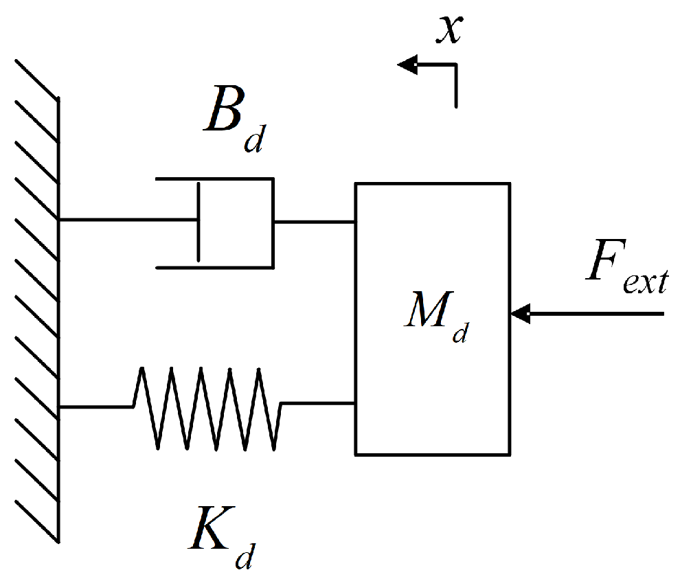
Figure 1. Impedance dynamics model.
Fractalfract 07 00052 g001
Figure 2. Robot manipulator FOIC control system diagram.
Fractalfract 07 00052 g002
Figure 3. All FOIC satisfying the given ω c and φ m .
Fractalfract 07 00052 g003
Figure 4. J ITSE of FOIC corresponding to u.
Fractalfract 07 00052 g004
Figure 5. The Fourier series excitation trajectory.
Fractalfract 07 00052 g005
Figure 6. Measured and calculated joint-driving torque values.
Fractalfract 07 00052 g006
Figure 7. Robot manipulator FOIC simulation system.
Fractalfract 07 00052 g007
Figure 8. Comparison of approximated Bode diagram and true Bode diagram.
Fractalfract 07 00052 g008
Figure 9. Open-loop Bode diagram of FOIC.
Fractalfract 07 00052 g009
Figure 10. Force step response of the FOIC with dynamic inertia and gravity disturbance changes.
Fractalfract 07 00052 g010
Figure 11. The force step responses of FOIC with friction disturbance.
Fractalfract 07 00052 g011
Figure 12. Force step response of the FOIC with inertia, gravity, and friction disturbances.
Fractalfract 07 00052 g012
Figure 13. Force step response of the DFF-FOIC with dynamic disturbances.
Fractalfract 07 00052 g013
Figure 14. Experimental setup.
Fractalfract 07 00052 g014
Figure 15. Force step response curve comparison for IOIC and FOIC.
Fractalfract 07 00052 g015
Figure 16. Pole plot of the designed FOIC closed-loop control system.
Fractalfract 07 00052 g016
Figure 17. Bode sensitivity plot of FOIC and IOIC for robot manipulator control systems.
Fractalfract 07 00052 g017
Figure 18. Pole plot of the designed FOIC closed-loop control system considering the robot manipulator system.
Fractalfract 07 00052 g018
Figure 19. Force step response curve comparison for FOIC and DFF-FOIC.
Fractalfract 07 00052 g019
Figure 20. Joint-tracking curve comparison of FOIC and DFF-FOIC. (a) j o i n t 2 . (b) j o i n t 3 .
Fractalfract 07 00052 g020
Figure 21. Robustness examination for DFF-FOIC.
Fractalfract 07 00052 g021
Figure 22. Performance comparison of FOIC, DFF-FOIC, NSGA-IC and DFF-NSGA-IC.
Fractalfract 07 00052 g022
Table 1. The coefficients of the Fourier series excitation trajectory.
i a 1 , i a 2 , i a 3 , i a 4 , i a 5 , i
1−0.0768−0.0675−0.04570.05210.1379
2−0.1505−0.0172−0.13070.29540.0030
3−0.05760.01770.0479−0.69200.6840
i b 1 , i b 2 , i b 3 , i b 4 , i b 5 , i
1−0.05710.2280−0.08090.4996−0.4309
2−0.17950.2032−0.08090.27860.0938
30.00190.2032−0.08090.18520.1510
Table 2. Base dynamic parameters of the ERC20-C10.
Item z z 1 (Kgm 2 ) x x 2 (Kgm 2 ) x y 2 (Kgm 2 ) x z 2 (Kgm 2 ) y z 2 (Kgm 2 )
Value27.88541116.4740−11.92438.63456−13.4807
Item z z 2 (Kgm 2 ) m x 2 (Kgm) m y 2 (Kgm) x x 3 (Kgm 2 ) x y 3 (Kgm 2 )
Value70.4156−10.124948.613827.8231−2.0144
Item x z 3 (Kgm 2 ) y z 3 (Kgm 2 ) z z 3 (Kgm 2 ) m x 3 (Kgm) m y 3 (Kgm)
Value−7.482920.6031−3.664017.57604.0855
Item J 3 (m 2 ) T c 1 + (Nm) T c 1 (Nm) B m 1 (Nms/rad) T c 2 + (Nm)
Value12.975262.00688−93.8778116.3661176.8584
Item T c 2 (Nm) B m 2 (Nms/rad) T c 3 + (Nm) T c 3 (Nm) B m 3 (Nms/rad)
Value−38.5557119.639117.64926−47.827789.00266
xxi, xyi, xzi, yyi, yzi, zzi are the moments of inertia of link i about the center of its frame, mxi, myi, mzi are the first moment of link i, mi is the mass of link i, Tci+ and Tci are the Coulomb friction coefficients of jointi, Bmi is the viscous friction coefficient of jointi, Ji is the motor inertia (output shaft referred) of jointi.
Table 3. Simulation system components and function.
ComponentFunction
FOICAdjust the dynamic relation between the contact
force error and robot end position
Robot
System
Inverse KinematicCalculate the joint position command Q c m d , a
six-dimension vector consisting of all the joint command
of the 6-Axis robot manipulator, according to the robot
end command in cartesian coordinate
Servo
System
Control
Loop
Consist of position-control-loop, velocity-control-loop
and current-control-loop
Motor
Model
A motor model with friction and inertia
Dynamic
Disturbance
The inverse dynamic results are used as the dynamic
disturbance for the servo system, to simulate the
 influence of inertia, gravity and friction in the real
physical environment
Dynamic
Feedforward
Controller
Calculate the driving torque corresponding to the
desired kinematic command Q c m d according to
Equation (36). Transform the driving torque to driving
current by K f f and compensate the dynamic
disturbance
K d i s Conversion coefficient between disturbance torque
and current
K f f Conversion coefficient between dynamic feedforward
torque and current
Forward
Kinematic
Calculate the position of the robot end in cartesian
coordinate according to the joint real position Q r e a l ,
a six-dimension vector consisting of real position of
every joint of the 6-Axis robot manipulator
K s Simulate the external spring stiffness contacting with
the end of robot
Force SensorObtain the real contact force
Table 4. Puma560 modified Denavit–Hartenberg (DH) parameters.
LinkJoint Offset (d) (m)Link Length (a) (m)Link Twist ( α ) (rad)
1001.5708
200.43180
30.150050.0203−1.5708
40.431801.5708
500−1.5708
6000
Table 5. Puma560 dynamic parameters.
x x (Kgm 2 ) x y (Kgm 2 ) x z (Kgm 2 ) y y (Kgm 2 ) y z (Kgm 2 )
l i n k 1 00000
l i n k 2 0.13000.5240
l i n k 3 0.066000.01250
z z (Kgm 2 ) m x (Kgm) m y (Kgm) m z (Kgm)m (Kg)
l i n k 1 0.350000
l i n k 2 0.5391.18320.1044−0.278417..4
l i n k 3 0.0660−0.3360.06724.8
T c + (Nm) T c (Nm) B m (Nms/rad)G J m (Kg m 2 )
j o i n t 1 0.395−0.4350.00148−62.610.000291
j o i n t 2 0.126−0.0710.000817107.80.000409
j o i n t 3 0.132−0.1050.00138−53.710.00299
xx, xy, xz, yy, yz, zz are the moments of inertia about the center of gravity (COG), mx, my, mz are the first moment, m is the link mass, Tc+ and Tc are the Coulomb friction coefficients, Bm is the viscous friction coefficient, G is the gear ratio, Jm is the motor inertia (motor referred).
Table 6. Experimental setup description and parameters.
ItemsBrand and ModelDescription
Robot
manipulator
EFORT ERC20C-C10Degree-of-freedom: 6;
Maximum load: 20 Kg;
Industrial
computer
ADVANTECHMain board: advantech AIMB-785; 
Processor: Intel Core T M  i7-7700/ 3.6 GHz;
Servo
drive
TSINO DYNATRON
CoolDrive R6
Maximum EtherCAT 
communication frequency: 4 KHz;
Force
 sensor
HPS-FT060ERange in Z-axis: ±1000 N; 
Measurement accuracy: 0.4 N; 
Maximum EtherCAT
communication frequency: 2 KHz;
Spring Stiffness: 1293.83 N/m;
Table 7. ERC20-C10 modified DH parameters.
LinkJoint Offset (d) (m)Link Length (a) (m)Link Twist ( α ) (rad)
10.5040.168461.5708
200.781550
300.140341.5708
40.760390−1.5708
5001.5708
60.12500
Table 8. Force step response average performance comparison for IOIC and FOIC with ten repetitions.
IOICFOICComparison
Rising time (s)0.06140.06110.4886%
Overshoot (N)76.68%74.73%2.54%
Settling time (s)0.53590.479110.60%
ITAE0.37910.34788.2564%
Table 9. Anti-disturbance response average performance comparison of IOIC and FOIC for ten repetitions.
IOICFOICImprovement Comparison of FOIC
Settling time (s)0.75480.70516.5845%
ITAE0.21090.20811.3276%
Table 10. Force step response performance comparison for FOIC and DFF-FOIC.
FOICDFF-FOICComparison
Rising time (s)0.0610.0616.39%
Overshoot (N)75.62%67.33%10.96%
Settling time (s)0.4740.4319.07%
ITAE0.36190.31712.41%
Table 11. ITAE joint-tracking comparison of FOIC and DFF-FOIC.
FOICDFF-FOICComparison
J o i n t 2 0.00990.005544.44 %
J o i n t 3 0.0040.002537.5 %
Table 12. Force step response performance comparison of FOIC, DFF-FOIC, NSGA-IC, and DFF-NSGA-IC.
NSGA-ICFOICDFF-NSAGDFF-FOIC
Rising time (s)0.0830.0740.0830.074
Overshoot (N% )72.09%74.03%70.94%72.87%
Settling time (s)1.3110.9101.2040.781
ITAE2.7511.8132.5991.260
Disclaimer/Publisher’s Note: The statements, opinions and data contained in all publications are solely those of the individual author(s) and contributor(s) and not of MDPI and/or the editor(s). MDPI and/or the editor(s) disclaim responsibility for any injury to people or property resulting from any ideas, methods, instructions or products referred to in the content.