1. Introduction
Generally, by long-time complex geological processes, there are many discontinuous geological structural planes such as joints and fissures in the natural rock mass, which can be called jointed rock mass [
1,
2]. For the jointed rock mass, influenced by the geological structure of complex joint interfaces, its mechanical properties are discontinuous. Generally, the jointed rock mass can be divided into two parts, which are matrix rock and joint interface. Because the strength of joint interface is generally less than that of matrix rock, the fracture of jointed rock mass often generates from the defect in the joint interface, called joint interfacial crack. Therefore, the influence of joint interface on the fracture feature of jointed rock mass is obvious, and there is a big difference in the fracture feature between the jointed rock mass and intact rock mass [
3]. The previous studies [
4,
5] show that for jointed rock mass, under loading, generally, the interfacial crack will initiate along the joint interface. However, when the strength of matrix rock for the jointed rock mass is weak and is as similar as that of joint interface, under loading, the direction of interfacial crack initiation may change, and the fracture will invade into the matrix rock. Therefore, the fracture features of jointed rock mass are complex.
Nowadays, the fracture features of intact rock mass have been studied by using the theories of fracture mechanics, which are called rock fracture mechanics [
6]. Additionally, there are many theoretical studies on fracture features of intact rock mass [
7,
8,
9]. Moreover, currently, the peridynamic model [
10] has received a worldwide attention for analysis of the fracture features of rock cracks by numerical methods [
11,
12]. However, the studies on the fracture features of close joint interface for the jointed rock mass are lacking. In the traditional fracture mechanics [
13,
14], the fracture toughness of materials is taken as the single index to judge the crack initiation. However, to study the interfacial fracture features of jointed rock mass under the compression-shear, for the difference of fracture toughness of matrix rock and joint interface, the fracture toughness on the different directions of joint interfacial crack initiation (along the joint interface and into the matrix rock) is different. Therefore, the features of the joint interfacial crack initiation cannot be analyzed easily.
Actually, for the similarity of jointed rock mass and composites (all are composed by two parts, intact materials and their contact interfaces), to study the interfacial fracture features of jointed rock mass, the interface fracture mechanics widely used for analysis of the interfacial crack of the composites (bimaterials) [
15,
16] can be applied. However, for the composites, the stress field at interfacial crack tip exhibits oscillatory singularity induced by mismatching of the dissimilar materials on both sides of the interface [
16,
17]. This is much different from that of jointed rock mass because both sides of a joint interface are the same materials. Moreover, for the composites, if the materials on both sides of the interface are the same, it can be considered as one material. However, for the jointed rock mass, the joint interface affects its mechanical properties seriously, thus, the influence of joint interface on the fracture of jointed rock mass must be considered. Moreover, there are some studies on bodies with cracks partially healed by non-contrast material [
18,
19], which is as similar as the jointed rock mass. However, in these studies, based on the analysis of crack fracture by fracture mechanics, the mechanical properties of the materials have been researched by using the limit equilibrium, etc. Therefore, these studies are from the macro-scale, while the studies presented here are from the meso-scale.
From the above analysis, in this study, to study the fracture mechanic features of jointed rock mass, the basic theories of interface fracture mechanics are applied to analyze the interfacial fracture of jointed rock mass. Additionally, the joint interfacial crack initiation was researched comprehensively. At last, the theoretical studies were verified by the numerical tests using the PFC2D 6.0 software which is sourced by Itasca Consulting Group, Inc in Minneapolis, MN, USA.
2. Interfacial Fracture Features of Jointed Rock Mass
Interface fracture mechanics have firstly been used to study the interfacial fracture of composites [
20]. The composites are the combined materials mutually bonded by two different or identical materials [
21]. However, the jointed rock mass is composed by rock and joint interface. Therefore, for the composites and jointed rock mass, their structure is similar because they are all composed by the materials and their interfaces. Actually, for both composites and jointed rock mass, their interface is the intermediate zone filled by another material with some meso-defects whose mechanical property is different from those of the matrix materials. The defects in the jointed rock mass include holes, fissures, weak inclusions, micro-geological anomalies, etc. In this study, for simplicity, to establish the mechanical model of jointed rock mass with interfacial cracks, only the main defects, which are holes and fissures, were considered. Therefore, according to the basic theories of interface mechanics [
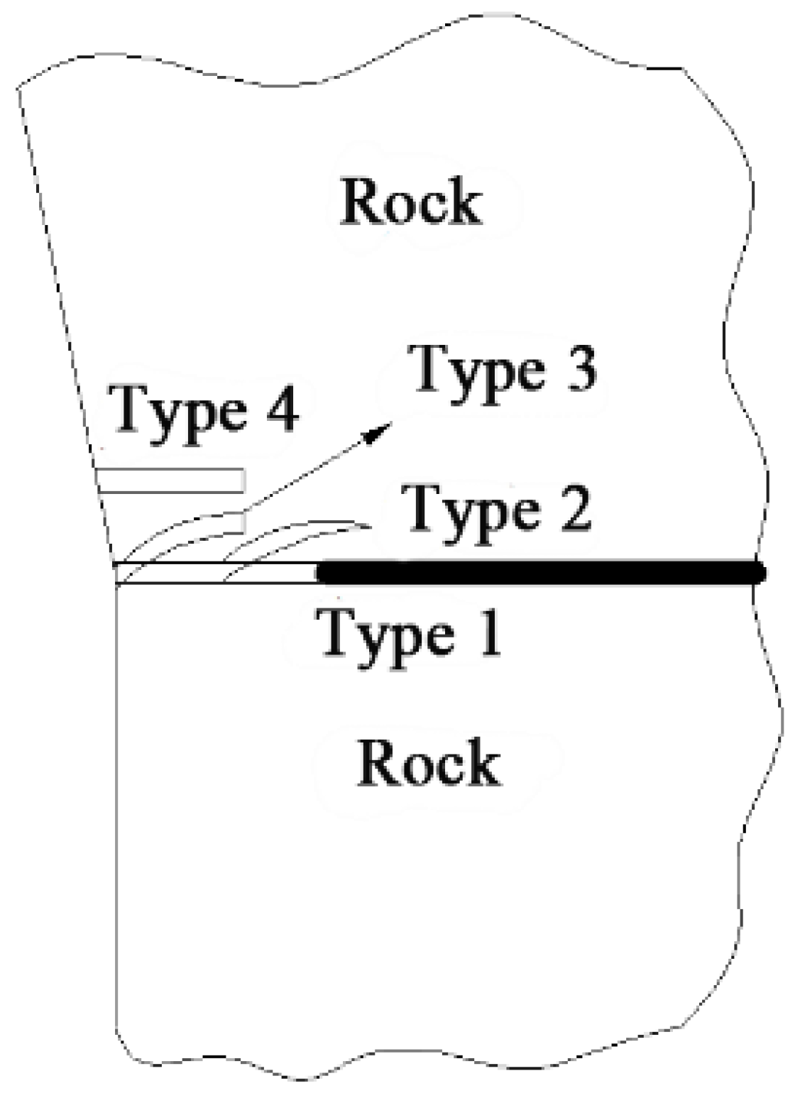
22], the interfaces in the jointed rock mass can be divided into three types, which are fully bonded interface, debonding interface, and contact interface, as shown in
Figure 1.
As for the jointed rock mass, its load-bearing capacity is determined by the strength of rock materials and their interfaces. Generally, the interfacial zone of the composites is filled by another material whose bonding strength is high, and thus, the interface strength of the composites is not lower than that of matrix material. However, for the jointed rock mass, the joint interface is generally filled by the rock weathering materials or other soft materials, whose bonding strength is low, therefore, the interface strength of the jointed rock mass is lower than that of matrix rock. Because the fracture of jointed rock mass is generally controlled by its interface strength, the fracture is more likely to occur along the interface. Therefore, according to the basic theories of interface mechanics [
22], for the jointed rock mass, the interfacial fracture can be divided into four types based on the origination position and development direction of the interfacial fracture, as shown in
Figure 2.
The first type is called the complete interface fracture, for which the interface is completely separated because the bonding strength of the interface is very low. The second type is called the mixed fracture of interface and matrix rock. For this kind of fracture, the interface strength is as similar as that of matrix rock, and under this condition, the fracture direction can be along the interface or turn into matrix rock, that is to say, the interfacial fracture develops along a random direction. For the third type, the interface strength is higher than that of matrix rock, for which the fracture is originated at the defect of interface and developed in the matrix rock. For the fourth one, the interface strength is high and the plastic deformation of matrix rock is large, for which the fracture develops in the matrix rock along a direction roughly parallel to the interface. Therefore, the interfacial fracture mode of the jointed rock mass is determined by the interface strength, strength of matrix rock, and the stress state. That is to say, the interfacial fracture features of jointed rock mass are mainly controlled by the inter-relationships between the interface strength and the matrix rock strength.
In the rock fracture mechanics [
6], the defects in the rock mass can be simplified as the cracks in the mechanical model. In this simplification, the simplified terms mainly include the shape and width of the defects. Because the jointed rock mass is generally in the complex stress state, and the joint interface is under compression-shear, the cracks in the joint interface will be mode I–II composite cracks. Under loading, the stress state of the unit at the interfacial crack tip is as shown in
Figure 3.
Thus, the stresses at the interfacial crack tip can be described as
where
are the stresses at the crack tip.
are the stress intensity factors of mode I and II cracks.
r is the radial coordinate.
is the direction angle of the crack in the polar coordinate.
In the fracture mechanics [
13], the stress intensity factors can be described as
where
and
are the tensile and shear stresses at the crack tip, and
a is the half length of the crack.
In the interface mechanics, the stress field at the interfacial crack tip can also be described by the stress intensity factor [
22]. Therefore, as shown in
Figure 4, the stress at the interfacial crack tip can be described as
where
j = 1, 2.
.
h can be taken as
according to the real condition, and
.
are the stress intensity factors described as
and
.
.
,
.
3. Interfacial Crack Initiation Criterion of Jointed Rock Mass
As for the jointed rock mass, there are many joint structural planes. Moreover, the mechanical property of the joint interface is generally poorer than that of matrix rock. Therefore, there is an obvious anisotropy for the jointed rock mass. In this study, to research the joint interfacial crack initiation of the jointed rock mass, the mode Ι fracture toughness of the matrix rock and joint interface are defined as
and
, respectively. From the basic theories of rock fracture mechanics [
6], the direction of joint interfacial crack initiation is determined by the relative size of ratio of the maximum stress intensity factor for the matrix rock to the fracture toughness of matrix rock and the ratio of the stress intensity factor along the joint interface to the fracture toughness of joint interface.
From Equation (1), the hoop stress at the mode I–II composite crack tip is,
In order to better analyze the interfacial crack initiation, the stress intensity factors in different direction angles
θ near the crack tip can be defined as [
23]
Let us define the equivalent stress intensity factors.
For the matrix, , and for the interface, .
Here, is the angle of crack initiation, and is the angle of orientation of the interface relative to the crack.
The condition that the direction of joint interfacial crack initiation is into the matrix rock is that the maximum stress intensity factor of mode I crack for the matrix rock (
) is larger than the mode I fracture toughness of matrix rock (
), that is,
The condition that the direction of joint interfacial crack initiation is along the joint interface is that the stress intensity factor of mode Ι crack along the joint interface (
) is larger than the mode Ι fracture toughness of the joint interface (
), that is,
If the ratio of the stress intensity factor of mode Ι crack along the joint interface to the mode Ι fracture toughness of joint interface is larger than that of the maximum stress intensity factor of mode Ι crack of matrix rock to the mode Ι fracture toughness of matrix rock, the joint interfacial crack will initiate along the joint interface, which is,
From Equation (8), there is,
Otherwise, the condition that the joint interfacial crack initiates into the matrix rock is,
Combining Equations (9) and (10), the criterion of interfacial crack initiation for jointed rock mass can be obtained as
Because for real rock engineering the jointed rock mass is generally under compression, and the interfacial crack is generally under the compression-shear, based on the obtained criterion of interfacial crack initiation for jointed rock mass, the jointed rock mass model under triaxial compression is used to analyze the interfacial crack initiation. As the unit model of jointed rock mass, the standard cylindrical specimen with the inclined throughout joint in which there is a crack under triaxial compression is shown in
Figure 5.
In this model, there is a crack in the joint interface, whose length is 2
a and dip angle is
. Moreover,
is the maximum principal stress, and
is the minimum principal stress. The ratio of minimum and maximum principal stress is described as
, called stress ratio, that is,
Because the joint interface of jointed rock mass is generally a smooth weak surface, for simplicity, the friction of interfacial crack surface is not considered here. Therefore, the stresses of crack in the joint interface can be described as
where
and
are the normal and shear stress on the interfacial crack surface, respectively.
The Equation (12) is substituted into Equation (13), and there is,
The Equation (14) is substituted into Equation (2). Because the 2D model of jointed rock mass is under bidirectional compression, and the stress direction is positive in tension and negative in compress, the stress intensity factors at the interfacial crack tip can be described as
The Equation (15) is substituted into Equation (4), and there is,
From Equation (16), the hoop stress along the joint interface at the interfacial crack (
) can be described as
Based on theories of fracture mechanics [
13], the crack initiation direction must satisfy the follow conditions, which are
and
. Therefore, for the cracks in the joint interface, there are,
From Equations (18) and (19), the angle of the joint interfacial crack initiation (
) can be obtained. The obtained
is substituted into Equation (16), and thus the hoop stress along the crack initiation direction can be obtained as
The Equations (17) and (20) are substituted into Equation (11), and there is,
Therefore, the Equation (21) is the criterion of interfacial crack initiation for jointed rock mass under triaxial compression. Because the mode Ι fracture toughness of matrix rock () is generally larger than that of the joint interface (), the value of is from 0 to 1.
If
, the model of jointed rock mass is only under the stress
. Therefore, the Equation (21) can be simplified as the criterion of interfacial crack initiation for jointed rock mass under uniaxial compression, which is,
4. Analysis of Interfacial Crack Initiation of Jointed Rock Mass
4.1. Influence of Joint Interface Dip Angle and Stress Ratio on the Critical Strength Ratio
As for any jointed rock mass, the direction of interfacial crack initiation is mainly determined by the ratio of mode Ι fracture toughness of matrix rock to that of the joint interface. Here, the ratio of hoop stress of interfacial crack along the joint interface to the maximum hoop stress is defined as critical strength ratio
, which is,
When the ratio of mode Ι fracture toughness of the joint interface to that of the matrix rock is smaller than the critical strength ratio, the direction of interfacial crack initiation is along the joint interface. Additionally, the larger the critical strength ratio is, the more easily the interfacial crack initiates along the joint interface.
The results of relationships between critical strength ratio, stress ratio, and dip angle of joint interface are as shown in
Figure 6.
From
Figure 6, it can be found that under the condition of the same dip angle of joint interface, as the stress ratio
increases, the critical strength ratio increases too. Moreover, the minimum value of critical strength ratio for the different dip angle of joint interface increases as
increases too. When
is larger than 0.6, the critical strength ratio is larger than 0.9, and the larger the
is, the closer to 1.0 the critical strength ratio will be. Because under real conditions the ratio of mode Ι fracture toughness of the joint interface to that of matrix rock is less than or equal to 1.0, the interfacial crack will initiate along the joint interface when the critical strength ratio is 1.0.
In addition, for the same λ, the critical strength ratio will decrease firstly and then increase as the dip angle of joint interface increases, but the dip angle of joint interface corresponding to the turning point of critical strength ratio will increase gradually. When the dip angles of joint interface are 0 and 90 degrees, the critical strength ratios are all 1.0, that is, the interfacial crack will initiate along the joint interface. However, under the other dip angles of joint interface, the direction of interfacial crack initiation will be determined according to its stress state, jointed rock mass type, etc.
4.2. Influence of Jointed Rock Mass Type on the Interfacial Crack Initiation Angle
In this study, three types of jointed rock mass were considered, for which the ratios of mode I fracture toughness of the joint interface to that of matrix rock are 0.6, 0.7, and 0.8, respectively. For these three types of jointed rock mass, the computed interfacial crack initiation angles under triaxial compression are summarized in
Table 1,
Table 2 and
Table 3.
It must be noted that, in these tables, when the angle of interfacial crack initiation is 0°, the direction of interfacial crack initiation is along the joint interface.
From
Table 1,
Table 2 and
Table 3, it can be found that, for the same loading and same dip angle of joint interface, the angle of interfacial crack initiation is determined by the jointed rock mass type. As the stress ratio
increases gradually, when the dip angles of joint interface are small (0 and 15 degrees) or very large (90 degrees), the interfacial crack initiation angles are always 0 degrees. However, for other dip angles of joint interface, as
increases gradually, the interfacial crack initiation angles decrease gradually to 0 degrees, that is, the direction of interfacial crack initiation is from into the matrix rock to along the joint interface. Moreover, for the jointed rock mass with small stress ratio, as the dip angles of joint interface increase gradually, the direction of interfacial crack initiation is from along the joint interface to into the matrix rock. However, for that with large stress ratio, the direction of interfacial crack initiation is always along the joint interface.
In addition, comparing the
Table 1,
Table 2 and
Table 3, it can be found that, with the increase of
, for the same stress ratio and dip angle of the joint interface, the number of rock mass models for which the direction of interfacial crack initiation is into the matrix rock increases gradually. When the dip angles of joint interface are 0 and 90 degrees, the direction of interfacial crack initiation is always along the joint interface. However, for rock mass models with other dip angles of joint interface, the direction of interfacial crack initiation is much different with the increase of
, and some are changed from along the joint interface to into the matrix rock under the condition of the same dip angles of the joint interface and the same stress ratio. For example, when the dip angle of the joint interface is 45° and the stress ratio is 0.2, the interfacial crack initiation angles for three types of jointed rock mass are 0°, 46.06°, and 46.06°, respectively. Moreover, when the dip angle of the joint interface is 60°, and the stress ratio is 0.3, the interfacial crack initiation angles for three types of jointed rock mass are 0°, 45.24°, and 45.24°, respectively.
Because the joint interface of jointed rock mass is generally filled by the rock weathered materials, the fracture toughness of the joint interface is weak. Therefore, for the jointed rock mass, if the strength of matrix rock is weak, the will be large, and then, the interfacial crack initiation will easily invade into the matrix rock under the same conditions. According to the above analysis, for the jointed rock mass in which the mechanical property of matrix rock is high, such as granite jointed rock mass, basalt jointed rock mass, etc., the interfacial crack initiates easily along the joint interface. However, for the jointed rock mass in which the mechanical property of matrix rock is poor, such as sandstone jointed rock mass, mudstone jointed rock mass, etc., the interfacial crack initiation will easily invade into matrix rock.
5. Verification by the Numerical Study
Because it is very hard to operate the lab tests and it is hard to observe the process of interfacial crack initiation, nowadays, the lab tests to study the joint interface fracture of the jointed rock mass are very lacking. However, it is suitable to analyze the process of interfacial crack initiation for jointed rock mass by using the numerical method [
24,
25]. Therefore, to verify the theoretical studies in the above sections and analyze the interfacial crack initiation of jointed rock mass deeply, the numerical test on the jointed rock mass specimen was conducted. In this numerical test, by using the discrete element software of PFC2D, the triaxial compression tests on the jointed rock mass specimen of sandstone and granite were conducted to study the influence of jointed rock mass type and dip angle of joint interface on the interfacial crack initiation.
To calibrate the microscopic parameters of the numerical jointed rock mass specimen, based on the lab tests of the sandstone and granite in the literatures [
26,
27], 2D numerical models were constructed, whose length is 100 mm and width is 50 mm, as shown in
Figure 7. In this model, there is a joint interface, whose dip angle is as same as that in the real specimen (60 degrees).
By adjusting the microscopic parameters of the numerical model based on the trial and error method until the numerical results are as similar as the real ones (shown in
Figure 8), the suitable microscopic parameters can be obtained, as shown in
Table 4.
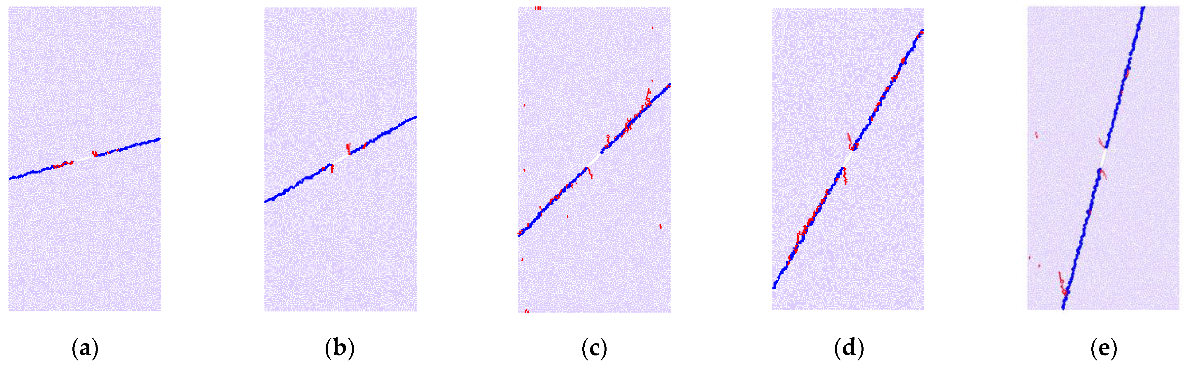
Using the calibrated microscopic parameters, the numerical models of standard specimens for jointed rock mass were constructed. In those numerical models, the dip angles of joint interface were set as 15°, 30°, 45°, 60°, and 75°, respectively. Moreover, there is a crack in the joint interface whose length is 10 mm. The numerical results of interfacial crack initiation for the sandstone and granite specimens are shown in
Figure 9 and
Figure 10.
It must be noted that, in the above two figures, the joint interface is described by the blue line, and the red parts are the generated cracks. Moreover, because the fracture toughness of granite is larger than that of sandstone, when the fracture toughness of the joint interface of those two rocks are similar, the ratio of fracture toughness of the joint interface to that of the matrix rock for granite is less than that for sandstone.
From
Figure 9, it can be found that, when the dip angle of the joint interface is 15°, the initiation angle of the interfacial crack is 0°, that is, the direction of the interfacial crack initiation is along the joint interface, as shown in
Figure 9a. However, when the dip angles of joint interface are 30°, 45°, 60°, and 75°, respectively, the direction of the interfacial crack initiation is into the matrix rock, and the initiation angle of interfacial crack is about 60°. Therefore, the above numerical results are in agreement with those of theoretical studies. For the numerical model of the sandstone jointed rock mass, the ratio of fracture toughness of the joint interface to that of the matrix rock is relatively larger. Thus, when the dip angle of joint interface is smaller, the direction of interfacial crack initiation will be along the joint interface. However, as the dip angle of joint interface increases gradually, the theoretically computed critical strength ratio will decrease gradually, and when it is less than the ratio of fracture toughness of the joint interface to that of the matrix rock, the phenomenon that the direction of interfacial crack initiation is into the matrix rock will appear, as shown in
Figure 9b–e.
From
Figure 10, when the dip angles of the joint interface are 15°, 30°, 45°, and 60°, respectively, the initiation angles of the interfacial crack are all 0°, that is, the direction of the interfacial crack initiation is along the joint interface. However, as shown in
Figure 10e, when the dip angle of the joint interface is 75°, the joint interfacial crack initiation will invade into the matrix rock, which is as similar as that for sandstone.
From
Figure 9 and
Figure 10, when the dip angle of the joint interface is small, the joint interfacial crack of two types of jointed rock masses will initiate along the joint interface. However, as the dip angle of the joint interface increases gradually, the theoretically computed critical strength ratio will decrease gradually. Additionally, when the critical strength ratio is less than the ratio of the fracture toughness of the joint interface to that of matrix rock, the joint interfacial crack initiation will invade into the matrix rock. Because the ratio of fracture toughness of the joint interface to that of the matrix rock for sandstone is larger than that for granite, under the same conditions, the joint interfacial crack initiation of sandstone will more easily invade into the matrix rock. For example, for sandstone, the phenomenon that the direction that the interfacial crack initiation is into the matrix rock will appear when the dip angles of the joint interface are 30°, 45°, 60°, and 75°, respectively. However, for granite, this phenomenon will appear only when the dip angle of the joint interface is 75°. Therefore, the results of numerical tests for two types of jointed rock masses verify the theoretical results well.


