Article

Fuzzy Fractional-Order PD Vibration Control of Uncertain Building Structures

1
College of Civil Engineering, Hefei University of Technology, Hefei 230009, China
2
School of Electrical Engineering and Automation, Hefei University of Technology, Hefei 230009, China
3
LAETA/INEGI, Faculty of Engineering, University of Porto, Rua Dr. Roberto Frias, 4200-465 Porto, Portugal
4
School of Economics, Hefei University of Technology, Hefei 230009, China
*
Author to whom correspondence should be addressed.
Fractal Fract. 2022, 6(9), 473; https://doi.org/10.3390/fractalfract6090473
Submission received: 19 July 2022 / Revised: 11 August 2022 / Accepted: 23 August 2022 / Published: 28 August 2022
(This article belongs to the Special Issue Advances in Fractional Order Systems and Robust Control)

Abstract

:
A new control strategy is proposed to suppress earthquake-induced vibrations on uncertain building structures. The control strategy embeds fuzzy logic in a fractional-order (FO) proportional derivative (FOPD) controller. A new improved FO particle swarm optimization (IFOPSO) algorithm is derived to adjust the initial parameters of the FOPD controller. An original fuzzy logic-FOPD (FFOPD) controller is then designed by combining the advantages of the fuzzy logic and FOPD control, to deal with large displacements on structures under earthquake excitation. Simulation experiments are carried out on uncertain building structures subjected to the effects of different kinds of seismic signals, illustrating the validity and feasibility of the proposed method.

1. Introduction

Earthquakes are major natural disasters that seriously threaten human life and property. Finding ways to reduce the influence of seismic waves on building structures is significant and challenging. The vibration control of structures has been shown to be promising and attracted much attention [1]. Many vibration control strategies have been proposed to improve the performance of structures under severe loadings, such as those induced by earthquakes and typhoons [2,3]. Indeed, passive, active and semi-active control methods have been studied to reduce the vibrations on building structures under earthquake excitation [4,5]. Recently, researchers have focused on active and intelligent control strategies due to their superior performance [6]. The most common are based on LQR [7], H 2 and H [8], sliding mode [9], bang–bang [10], proportional derivative (PD) [11], neural network [12], and optimal and fuzzy logic [13] control.
The PD controller has been widely used in engineering due to its simple structure, easy implementation, and remarkable effectiveness [14,15], and was also adopted to suppress vibrations on building structures under earthquake excitation [16]. However, in applications with high dynamical requirements, the traditional PD may perform poorly. To improve the performance of classical PD algorithms, the FOPD controller was introduced, taking advantage of the tools of the fractional calculus [17,18]. he FOPD controller is an extension of the traditional PD controller [19]. By adding an adjustable fractional order, the FOPD design can be more flexible, and attain better performance in term of improved steady-state error, good disturbance rejection, and superior behavior with nonlinearities [20]. Especially for time delay, nonlinear, and non-minimum phase systems, the FOPD controller can perform better than classical PD. Indeed, the FOPD scheme was successfully applied to motors [21], robots [22], building structures [23], autonomous underwater vehicles [24], and converters [25], to mention a few. Nevertheless, for complex systems and high-control performance requirements, the capacity of the FOPD is still limited.
The appropriate selection of the parameters of the FO controllers is determinant to the performance of the controlled systems. For most FOPD controllers, the parameters are constant and result from off-line optimization procedures. However, in the presence of unknown earthquakes, and uncertain and possibly variable system parameters, the controllers with fixed parameters may perform poorly.
Fuzzy logic controllers can be tuned online without knowing the systems’ exact mathematical models [26]. Moreover, they reveal good self-adaptability and robustness [27,28], leading to excellent dynamic performance [29].
In this paper a new FFOPD strategy is proposed to control the vibration of uncertain building structures under unknown earthquake excitation. The FFOPD combines the advantages of the FOPD controller, namely more degrees of freedom for tuning than the PD, and the fuzzy logic control, specifically its intrinsic good self-adaptability. The initial FOPD controller is designed in the discrete time domain, which overcomes the drawbacks associated with the Oustaloup’s approximations. The main contributions of this study are: (a) the derivation of a new IFOPSO algorithm for tuning the initial parameters of the FOPD controller; (b) the design of an original FFOPD control strategy for vibration control of uncertain structures; (c) the evaluation of the FFOPD’s effectiveness and robustness under different earthquake seismic excitation.
The paper is organized as follows. Section 2 introduces the basic concepts of fractional calculus and the vibration model of an uncertain building structure. Section 3 presents the IFOPSO algorithm and develops the new FFOPD strategy for controlling unwanted displacements of uncertain building structures. Section 4 applies the proposed method to a three-storey frame structure and assesses the controlled system performance. Finally, Section 5 draws the conclusions.

2. Preliminary Concepts and Model Description

2.1. Fractional Calculus

The FO integro-differential operator is a generalization of the classical integer-order one, meaning that we have [30]
t 0 D t ν = d ν d t ν , R ( ν ) > 0 , 1 , R ( ν ) = 0 , t 0 t ( d τ ) ν , R ( ν ) < 0 ,
where ν C is the order, and t 0 and t are the limits of the operation. There are several definitions for fractional derivative. The most commonly used are the Grünwald–Letnikov (GL), Riemann–Liouville (RL), and Caputo (C) formulations. The GL derivative of order ν of a function f ( t ) is given by
t 0 G L D t ν f ( t ) = lim h 0 f h ( ν ) ( t ) = lim h 0 h ν i = 0 [ t t 0 h ] ( 1 ) i i ν f ( t i h ) = lim h 0 1 Γ ( ν ) h ν i = 0 [ t ν h ] Γ ( ν + i ) Γ ( i + 1 ) f ( t i h ) ,
where [ · ] means the integer part of the argument, Γ ( · ) is the gamma function:
Γ ( z ) = 0 e t t z 1 d t = lim h n ! n z z ( z + 1 ) ( z + 2 ) ( z + n )
and
ν i = ν ( ν 1 ) ( ν 2 ) ( ν i + 1 ) i ! = ν i ! ( ν i ) ! .
In the discrete time, Equation (2) can be approximated by
t 0 G L D t ν f ( t ) = 1 T ν i = 0 r ( 1 ) i i ν f ( t i T ) ,
where T is the sampling period and r is the truncation order.
From the above, we verify that the fractional derivative includes information from the past, since it weights previous values of f ( t ) . This reflects the operator ability for capturing memory, which is not present in the integer-order operator.

2.2. Vibration Control System of Uncertain Building Structures

The differential dynamic equation of the building structure system under earthquake excitation is given as
M X ¨ ( t ) + C X ˙ ( t ) + K X ( t ) = E s V ( t ) .
Let us consider the general structure with parameter uncertainties and control input. The equation of motion of a n degrees-of-freedom uncertain building structure under earthquake excitation can be described as [9,23]
( M + Δ M ) X ¨ ( t ) + ( C + Δ C ) X ˙ ( t ) + ( K + Δ K ) X ( t ) = B s U ( t ) + E s V ( t ) ,
where M , C and K are the mass, stiffness and damping matrices, respectively. The matrices Δ M = α M , Δ C = β C and Δ K = γ K , where α , β and γ are the maximum rate of change of mass, damping and stiffness, respectively. Moreover, X ( t ) R n × 1 , X ˙ ( t ) R n × 1 and X ¨ ( t ) R n × 1 represent the displacement, velocity, and acceleration vectors of the building, respectively. The matrix B s R n × p stands for the actuators’ locations, vector U ( t ) R p × 1 denotes the actuators control forces, where p is the number of actuators, matrix E s R n × q stands for the external excitation locations, where q is the number of external excitations, E s V ( t ) = M L a ¨ ( t ) , where L is a unit column vector, and a ¨ ( t ) denotes the seismic wave acceleration, and vector F ( t ) R q × 1 denotes the external excitations. The matrices M and K can be written explicitly as:
M = m 1 0 0 0 0 m 2 0 0 0 0 m n 1 0 0 0 0 m n n × n , K = k 1 + k 2 k 2 0 0 k 2 k 2 + k 3 0 0 0 0 k n 1 + k n k n 0 0 k n k n n × n .
The Rayleigh damping matrix is given by C = α 1 M + β 1 K , where α 1 , β 1 R are determined by the value of the damping ratio of the two vibration modes, respectively. The calculation formula is as follows:
α 1 = 2 ω 1 ω 2 ξ 1 ω 2 ξ 2 ω 1 ω 2 2 ω 1 2 , β 1 = 2 ξ 2 ω 2 ξ 1 ω 1 ω 2 2 ω 1 2 ,
where, the damping ratios ξ i = 1 , 2 of all modes are set to 0.05, and ω 1 and ω 2 are the first and second mode circular frequencies of the structure, respectively. The vibration control system of the uncertain building structure is represented schematically in Figure 1. Displacement deviations are measured by means of sensors, providing input signals for the controller. The controller generates control actions that are sent to the actuators. Finally, the actuators output control forces to suppress earthquake-induced vibrations on the building structure.
Let us define the state variables Z ( t ) = [ X ( t ) X ˙ ( t ) ] 2 n × 1 T . The system Equation (7) can be written in the standard state-space form as [23,31],
Z ˙ ( t ) = ( A + Δ A ) Z ( t ) + ( B + Δ B ) U ( t ) + E F ( t ) , Y ( t ) = D Z ( t ) ,
where Y ( t ) is the output vector, D = [ I 0 ] 1 × 2 n , and
A = 0 I M 1 K M 1 C 2 n × 2 n , B = 0 M 1 B s 2 n × p , E = 0 M 1 E s 2 n × q , Δ A = 0 I Δ M K Δ M C 2 n × 2 n , Δ B = 0 Δ 1 M B s 2 n × p , Δ 1 M = α 1 + α M 1 , Δ M K = Δ 1 M ( K + Δ K ) + M 1 Δ K , Δ M C = Δ 1 M ( C + Δ C ) + M 1 Δ C .
The time-varying uncertain matrices Δ A and Δ B have appropriate dimensions and obey the condition
[ Δ A Δ B ] = G H ( t ) [ L 1 L 2 ] ,
where G and L are known constant real matrices, and H ( t ) is an unknown time-varying matrix, H T ( t ) H ( t ) I . The matrices G and L are
G = 0 0 M 1 M 1 2 n × 2 n , L 1 = γ α 1 + α K 0 0 β α 1 + α C 2 n × 2 n , L 2 = 0 α 1 + α B s 2 n × 2 n ,
and H ( t ) = δ t [ I ] 2 n × 2 n , with | δ t | 1 standing for an uncertain real scalar. The state space model (8) can be rewritten in the standard form
Z ˙ ( t ) = A ˜ Z ( t ) + B ˜ U d ( t ) , Y ( t ) = C ˜ Z ( t ) ,
where U d ( t ) = L a ¨ ( t ) + ( M 1 + Δ 1 M ) P f d , the variable P is a column vector representing the positions where the forces act, f d is the force output generated by the actuator, and
A ˜ = A + Δ A , B ˜ = [ 0 I ] 2 n × 2 n T , C ˜ = [ I 0 ] 1 × 2 n .
The actuator adopts the Active Bracing System (ABS) [31,32]. Vibration of buildings may be mitigated by means of ABS, which is placed between the ground and the first floor, or between two successive floors of the building [33]. Herein, we just consider the horizontal vibration of the building structure under earthquake excitation, and only address the design of the controller. The n-DOF shear frame equipped with an ABS between the ground and the first floor is shown in Figure 2.

3. Control Strategy

3.1. Improved Discrete FOPD Control

In this subsection, a discrete FOPD controller is designed. For practical computational implementation, we consider the FOPD with memory length truncation given by [30]:
U ( k ) = K p e ( k ) + j = 0 M K d h μ d j e ( k j ) .
However, memory truncation leads to system oscillation that must be mitigated. Herein, we propose the discrete FOPD:
U ( k ) = K p e ( k ) + j = 0 M K d h μ d j e ( k j ) + j = M + 1 k 1 K d h μ d M e ( k j ) , k > M ,
where d 0 = 1 and d j = ( 1 ( 1 μ ) / j ) d j 1 . The parameters K p and K d represent the proportional and differential gains, respectively, μ is the differential order, and e ( k ) stands for the input signal to the controller at the k-th time instant. Hereafter, we adopt M = 500 .
In the follow-up, an IFOPSO algorithm is proposed to optimize the initial values of the parameters K p , K d , and μ of the FOPD.

3.2. Improved FO Particle Swarm Optimization

The PSO is an intelligent optimization algorithm inspired in the swarm behavior of animals when searching for food and protection. The PSO was proposed by Kennedy and Eberhart [34]. The velocity and position of each particle are updated at the same time as follows:
υ i j ( t + 1 ) = ω υ i j ( t ) + c 1 ϕ 1 [ P b i j ( t ) χ i j ( t ) ] + c 2 ϕ 2 [ G b g j ( t ) χ i j ( t ) ] ,
χ i j ( t + 1 ) = χ i j ( t ) + υ i j ( t + 1 ) ,
where P b i j ( t ) is the best position found so far for each particle, G b g j ( t ) is the best position of the swarm, and c 1 and c 2 denote the coefficients of the particles accelerations. Variables ϕ 1 and ϕ 2 are randomly generated real numbers between 0 and 1, and ω is the velocity inertia weight. After calculating the velocity of each particle, the new position can be updated.
The PSO can be generalized in the light of the tools of fractional calculus, yielding the fractional PSO (FOPSO). Therefore, considering Equation (5) and ω = 1 , Equation (12) can be written as [35,36]:
D α υ i j ( t + 1 ) = c 1 ϕ 1 [ P b i j ( t ) χ i j ( t ) ] + c 2 ϕ 2 [ G b g j ( t ) χ i j ( t ) ] .
Taking the first four terms of the differential derivative given by Equation (5), then Equation (14) can be rewritten as:
υ i j ( t + 1 ) = α υ i j ( t ) + 1 2 α ( 1 α ) υ i j ( t 1 ) + 1 6 α ( 1 α ) ( 2 α ) υ i j ( t 2 ) + 1 24 α ( 1 α ) ( 2 α ) ( 3 α ) υ i j ( t 3 ) + c 1 ϕ 1 [ P b i j ( t ) χ i j ( t ) ] + c 2 ϕ 2 [ G b g j ( t ) χ i j ( t ) ] .
From (15), one can see that the PSO is a particular case of the FOPSO when α = 1 . In order to enhance the FOPSO algorithm so that it can better balance the local and global optimal solutions and increase the convergence speed, an improved FOPSO algorithm is proposed, yielding the IFOPSO.
Firstly, Equation (15) can be rewritten as:
υ i j ( t + 1 ) = α 1 υ i j ( t ) + 1 2 α 2 ( 1 α 2 ) υ i j ( t 1 ) + 1 6 α 3 ( 1 α 3 ) ( 2 α 3 ) υ i j ( t 2 ) + 1 24 α 4 ( 1 α 4 ) ( 2 α 4 ) ( 3 α 4 ) υ i j ( t 3 ) + c 1 ϕ 1 [ P b i j ( t ) χ i j ( t ) ] + c 2 ϕ 2 [ G b g j ( t ) χ i j ( t ) ] = ω 1 υ i j ( t ) + ω 2 υ i j ( t 1 ) + ω 3 υ i j ( t 2 ) + ω 4 υ i j ( t 4 ) + D α υ i j ( t + 1 ) ,
with ω i ( i = 1 , 2 , 3 , 4 ) denoting velocity weights, given by:
ω 1 = α 1 = λ 1 e v + λ 2 g d + 0.85 , λ 1 < 0 , λ 2 > 0 , ω 1 = α 1 ( 0.5 , 1 ) , ω 2 = 1 2 α 2 ( 1 α 2 ) , d ω 2 < 0 i f α 2 ( 0.5 , 1 ) , ω 3 = 1 6 α 3 ( 1 α 3 ) ( 2 α 3 ) , d ω 3 < 0 i f α 3 ( 0.42 , 1 ) , ω 4 = 1 24 α 4 ( 1 α 4 ) ( 2 α 4 ) ( 3 α 4 ) , d ω 4 < 0 i f α 4 ( 0 , 1 ) ,
where e v and g d are the evolution speed and aggregation degree factors of the swarm, respectively. Their expressions are:
e v = f ( P b e s t ( t ) ) f ( P b e s t ( t 1 ) ) , e v ( 0 , 1 ) ,
g d ( t + 1 ) = f ( G b e s t ( t ) ) 1 N i = 1 N f ( P b e s t i ( t ) ) , g d ( 0 , 1 ) .
The weight ω 1 is formulated as a function of e v and g d according to their impact on the search performance of the swarm. We know that ω 1 is negatively correlated with e v and positively correlation with g d . We set λ 1 = 0.35 and λ 2 = 0.15 , so that ω 1 is an adaptive variable related to the evolutionary state to ensure the global search ability. The α i ( i = 2 , 3 , 4 ) at the T-th iteration is calculated as:
α i = α m i n + α m a x α m i n T m a x T , α i [ 0.5 , 1 ] ,
where T and T m a x are the current iteration and the maximum number of iterations, respectively. As the number of iterations increases, α i ( i = 2 , 3 , 4 ) also increases, but the velocity weight ω i ( i = 2 , 3 , 4 ) decreases to ensure the local search ability. Through the above analysis, the proposed algorithm not only improves the convergence rate, but also searches the global optimal solution more effectively in the search domain.
The fitness function is the optimization goal of the algorithm. Herein, the integral of time multiplied by the absolute value of the error (ITAE) is used
J = t e ( t ) d t ,
where e ( t ) = r ( t ) y ( t ) is the difference between expected value and top displacement.
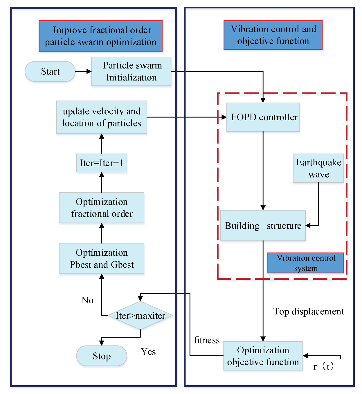
The algorithm comprises the following steps:
  • Step 1. Initialize the particle swarm. Randomly generate χ i j and υ i j of the particles, and determine P b e s t of each particle and G b e s t of the swarm;
  • Step 2. Calculate the fitness value of each particle. If it is good, then update P b e s t and G b e s t ;
  • Step 3. Use Equations (12) and (16) to update the velocity and location of the particles;
  • Step 4. Use Equations (18)–(20) to calculate the fractional-order α i ;
  • Step 5. Use Equation (17) to update the weight ω i ;
  • Step 6. Check stop conditions. If they are satisfied, then stop the search and output the results; Otherwise, return back to Step 2.
The flowchart of the IFOPSO algorithm is shown in Figure 3.
Table 1 summarizes the values of the FOPD parameters obtained with the PSO, FOPSO and IFOPSO algorithms. For the PSO and FOPSO we set ω = 0.85 and decrease it linearly.
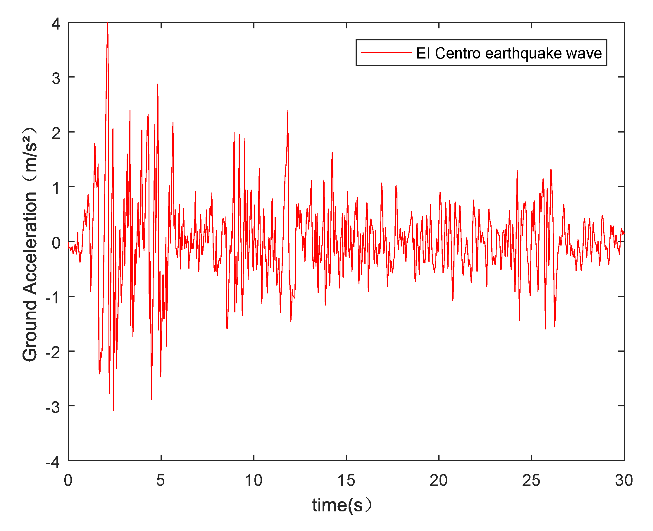
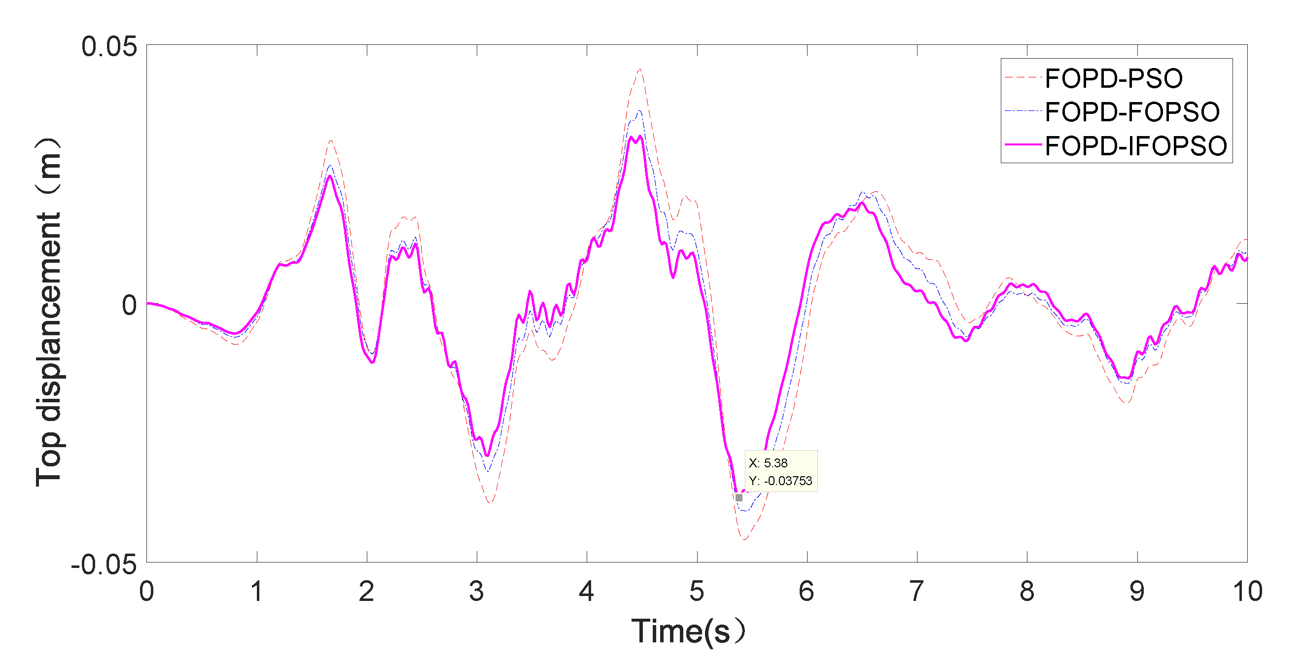
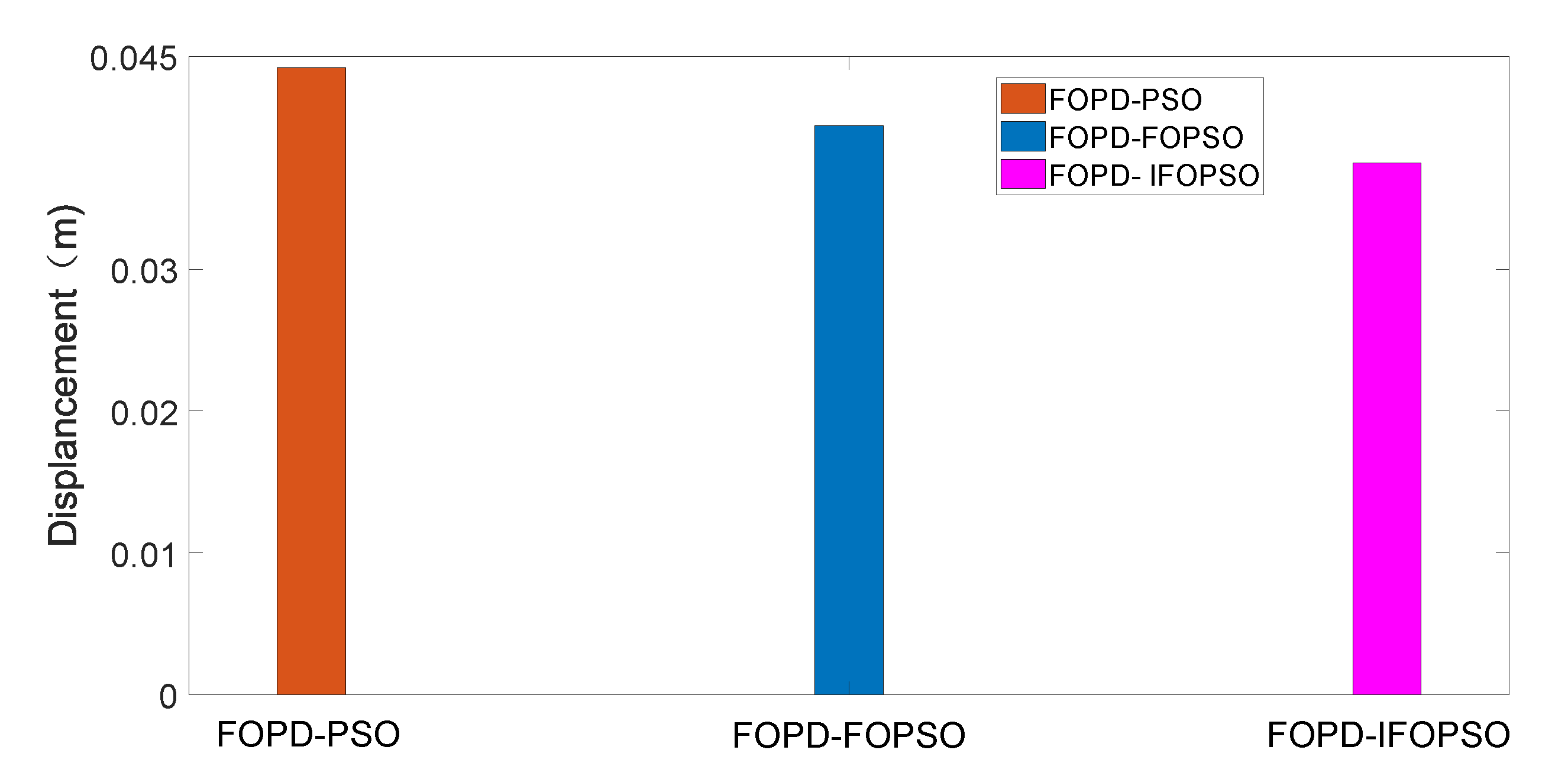
In order to verify the effectiveness of the IFOPSO, the FOPD controller was applied to the vibration control of a three-level building structure with model parameters shown in Table 2, and El-Centro earthquake seismic wave with maximum amplitude adjusted to 4 m/s 2 , as depicted in Figure 4. Figure 5 represents the vibration displacements versus time at the top of the building and Figure 6 shows the maximum displacement values. The displacements obtained with the FOPD-PSO, FOPD-FOPSO, and FOPD-IFOPSO are 0.0442 m, 0.0401 m, and 0.0375 m, respectively. This means that the maximum displacement for the FOPD-IFOPSO is reduced by 17.9% and 7.0%, when compared with the FOPD-PSO and FOPD-FOPSO, respectively, which reveals the superiority of the FOPD-IFOPSO.

3.3. FFOPD Controller

The parameters of the building structure, as well as the earthquake excitation, are often uncertain. Therefore, optimizing the parameters of the controller off-line, without taking into consideration system model and excitation uncertainty, results in poor control performance.
Fuzzy controllers can be used without an explicit mathematical model of the controlled system, and possess intrinsic adaptability to nonlinear, time-varying, and uncertain effects present in practical systems. To combine the advantages of the FOPD and the fuzzy logic control, we propose a new FFOPD controller given by
U ( k ) = K p ( k ) r 1 ( k ) e ( k ) + j = 0 M K d ( k ) r 2 ( k ) h μ ( k ) d μ ( k ) , j e ( k j ) + j = M + 1 k 1 K d ( k ) r 2 ( k ) h μ ( k ) d μ ( k ) , M e ( k j ) , k > M ,
where K p , K d , μ , r 1 and r 2 are arrays with length m. Setting the running time of the system t, then we have m = t / h . The two variables r 1 and r 2 regulate the fractional behavior of the whole algorithm.
Let e ( k ) = r ( t ) y ( t ) be the system error vector. The change rate of the system error at the τ -th time instant, e c ( k ) , can be expressed as
e c ( t ) = ( e ( t ) e ( t 1 ) ) / Δ t .
Both e and e c are chosen as input variables. The FOPD controller parameters Δ K p , Δ K d , Δ μ , Δ r 1 , Δ r 2 are the output variables of the fuzzy controller. The parameters’ self-tuning formula is
K p ( k ) = K p + Δ K p ( k ) , K d ( k ) = K d + Δ K d ( k ) , μ ( k ) = μ + Δ μ ( k ) , r 1 ( k ) = Δ r 1 ( k ) , r 2 ( k ) = Δ r 2 ( k ) .
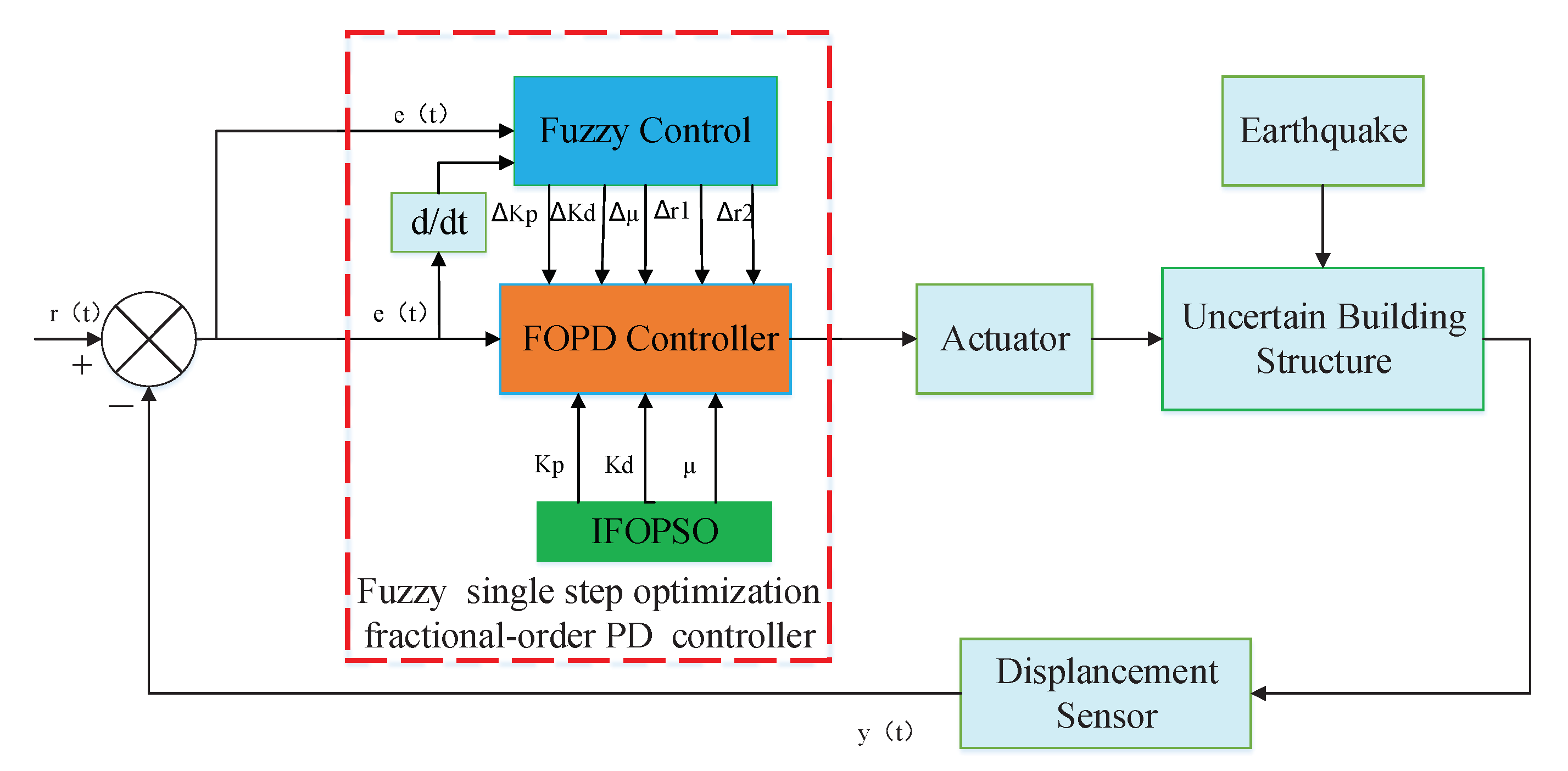
The fundamental structure of the new FFOPD scheme with five tuning parameters k p , k d , μ , r 1 , r 2 changing with the uncertain building structure response is showed in Figure 7. The fuzzy algorithm for the new controller involves four stages: fuzzy rule base, inference mechanism, fuzzification interface, and defuzzification interface.
It follows from the displacement response of the structure under FOPD control with initial parameters that the domain of the fuzzy controller parameters is as presented in Table 3.
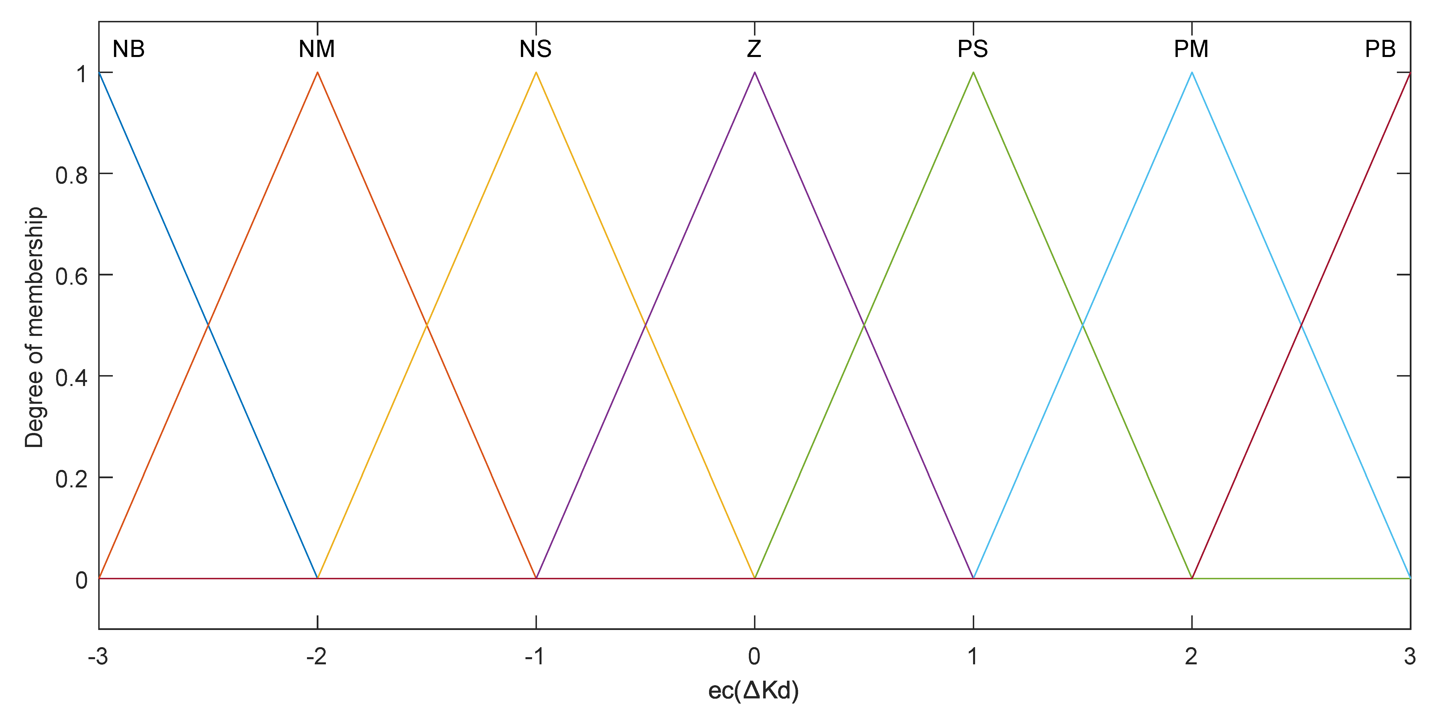
There are 7 fuzzy linguistic variables: negative big value (NB), negative medium value (NM), negative small value (NS), zero value (Z), positive small value (PS), positive medium value (PM), and positive big value (PB), as well as 49 rules in the rule base. The membership functions and fuzzy control rules of K p and K d are kept almost the same as for the conventional fuzzy PD controllers [37,38]. The fuzzy control rules of μ , r 1 and r 2 are designed according to the influence of them into the control system, which are tested repeatedly. A set of fuzzy rules that relates the input and output variables is established in Table 4 and Table 5. Figure 8, Figure 9, Figure 10 and Figure 11 depict the membership functions.
The control process of the FFOPD can be summarized as:
  • Based on the established fuzzy rules, the outputs of the adjusting values are obtained;
  • The actual real-time control parameters are calculated by the Equation (24);
  • The discrete FOPD controller and the fuzzy single step optimization control force U ( k ) at the k-th time instant are calculated by Equation (22).

4. Simulation Results and Analysis

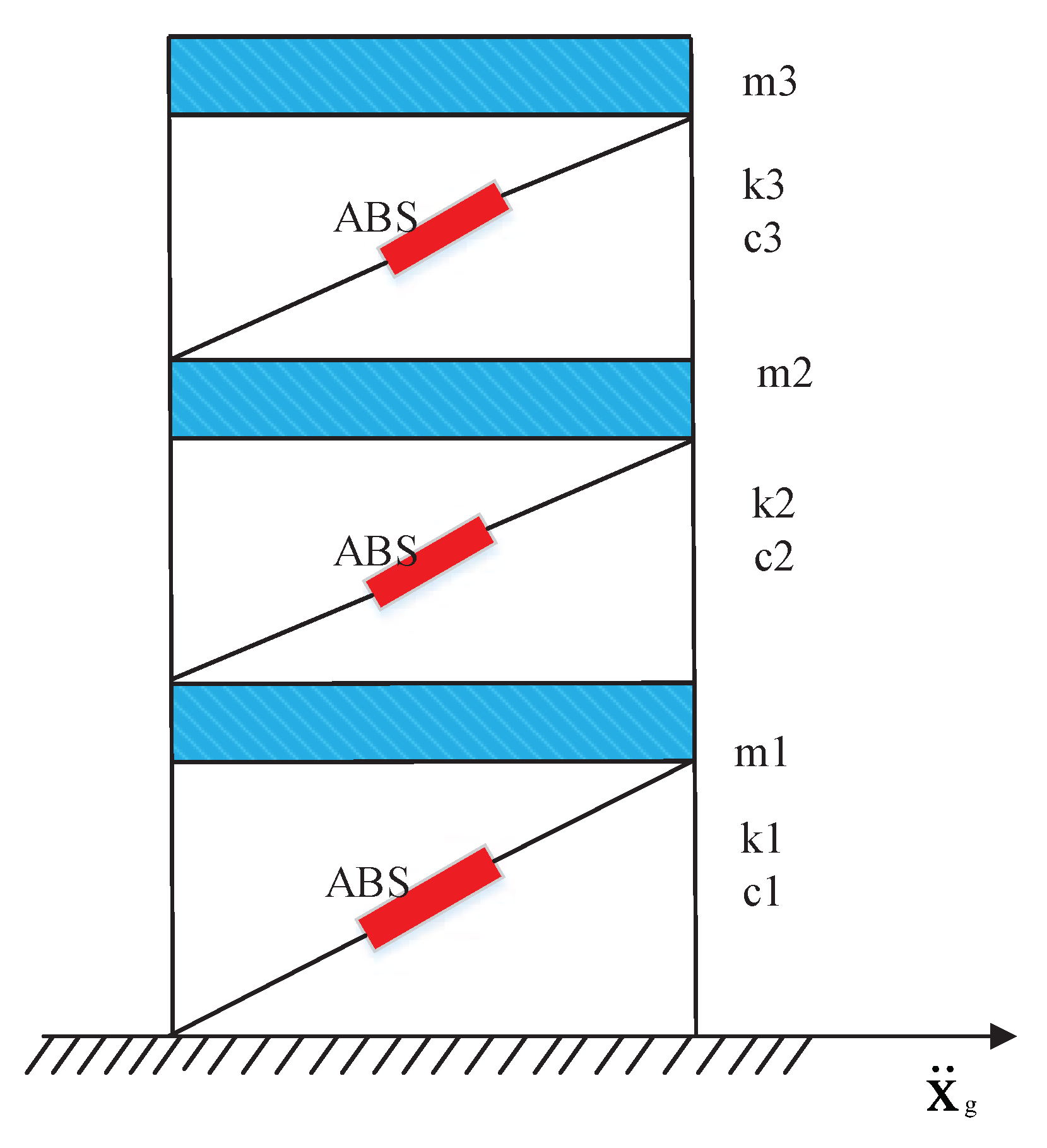
In this section, a three-storey building structure with actuators on each story is considered, as illustrated in Figure 12. The parameters of the uncertain building structure are given in Table 2.
The ground acceleration x g ¨ is assumed as the seismic records of the 1940 El-Centro and 1952 Taft earthquakes, with wave modulated with 0.4 g and 0.2 g amplitude for 10 s separately. The measured signal is applied to the control algorithm to generate a control signal for the control device. The displacement of the top level floor is used as the real time measured feedback. The duration of the control of the system overlaps with the period of excitation of the structure. The seismic wave is used as the excitation signal for the cases of uncontrolled system and PD, FOPD, and FFOPD control. The IFOPSO is used to optimize the controller initial parameters. The IFOPSO algorithm parameters used in this paper and the values of the initial parameters obtained through optimization are listed in Table 6.
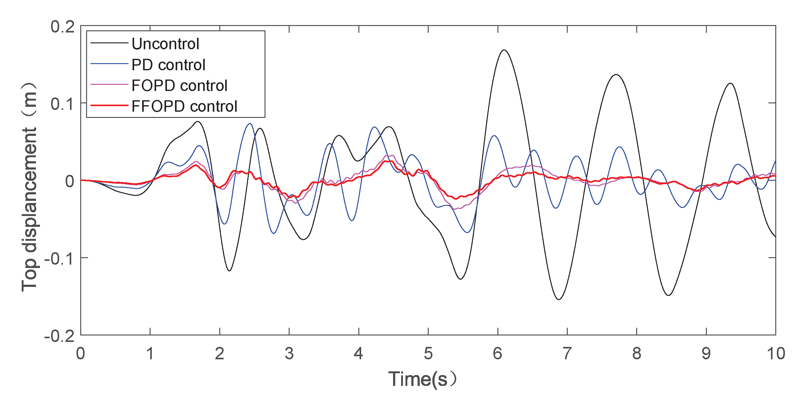
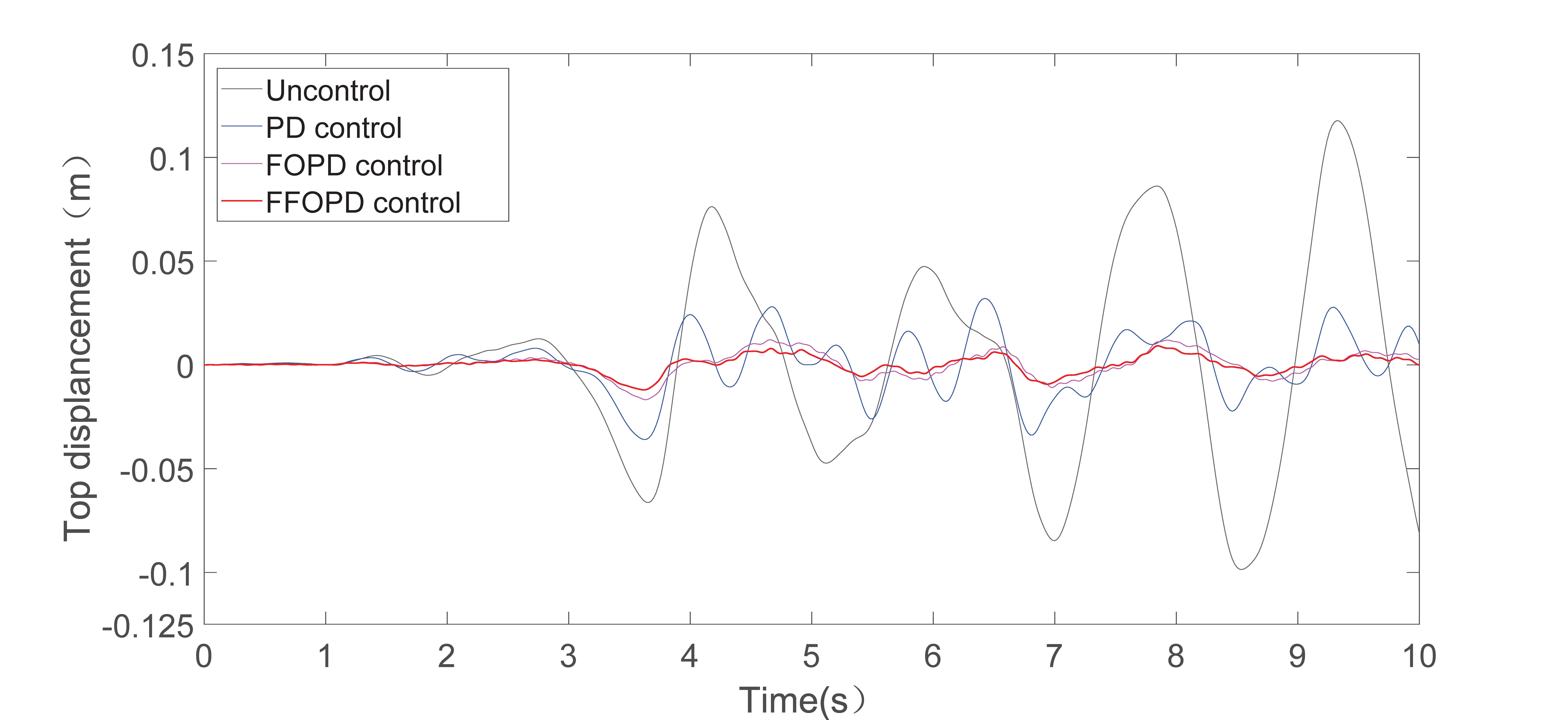
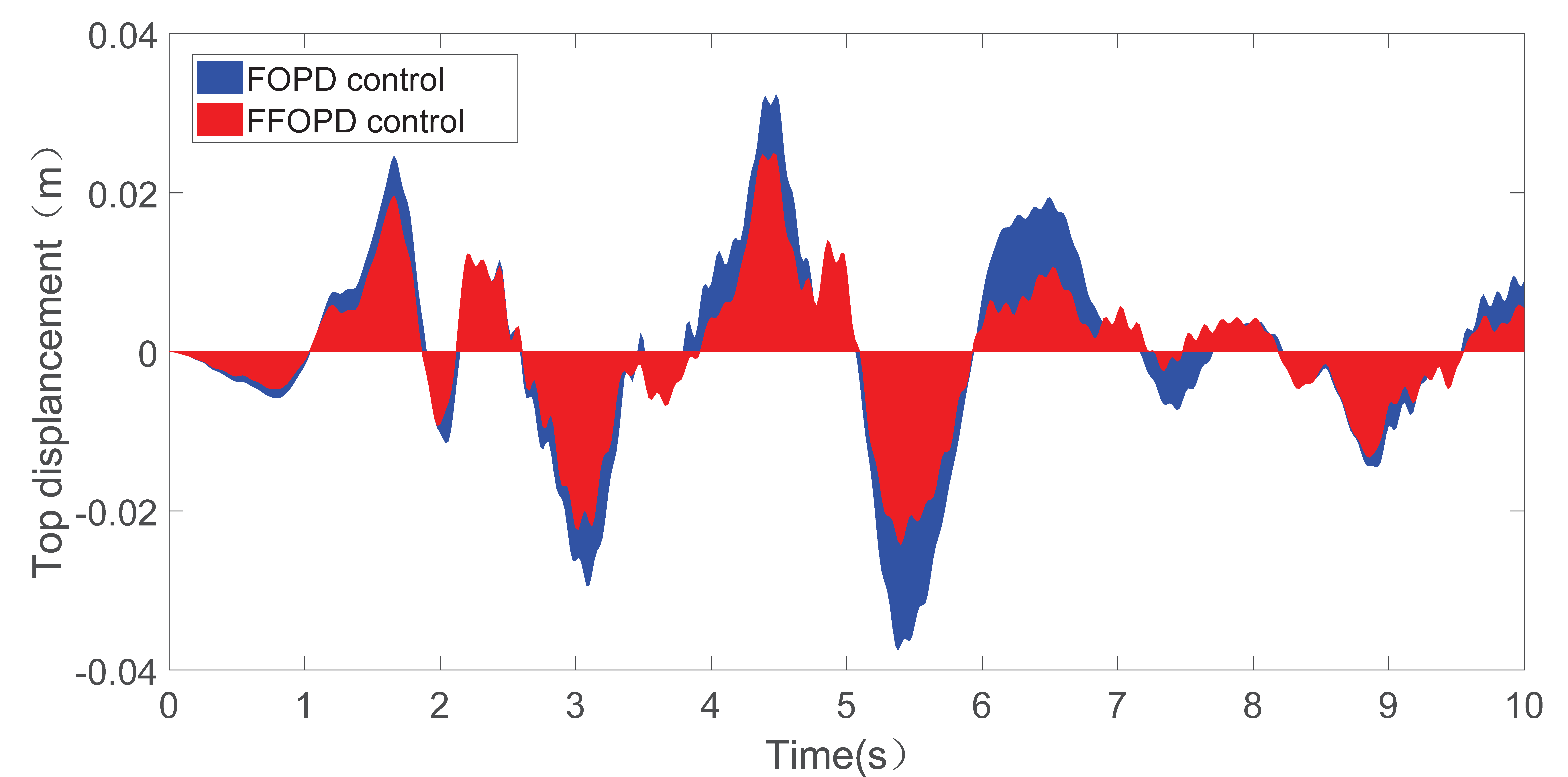
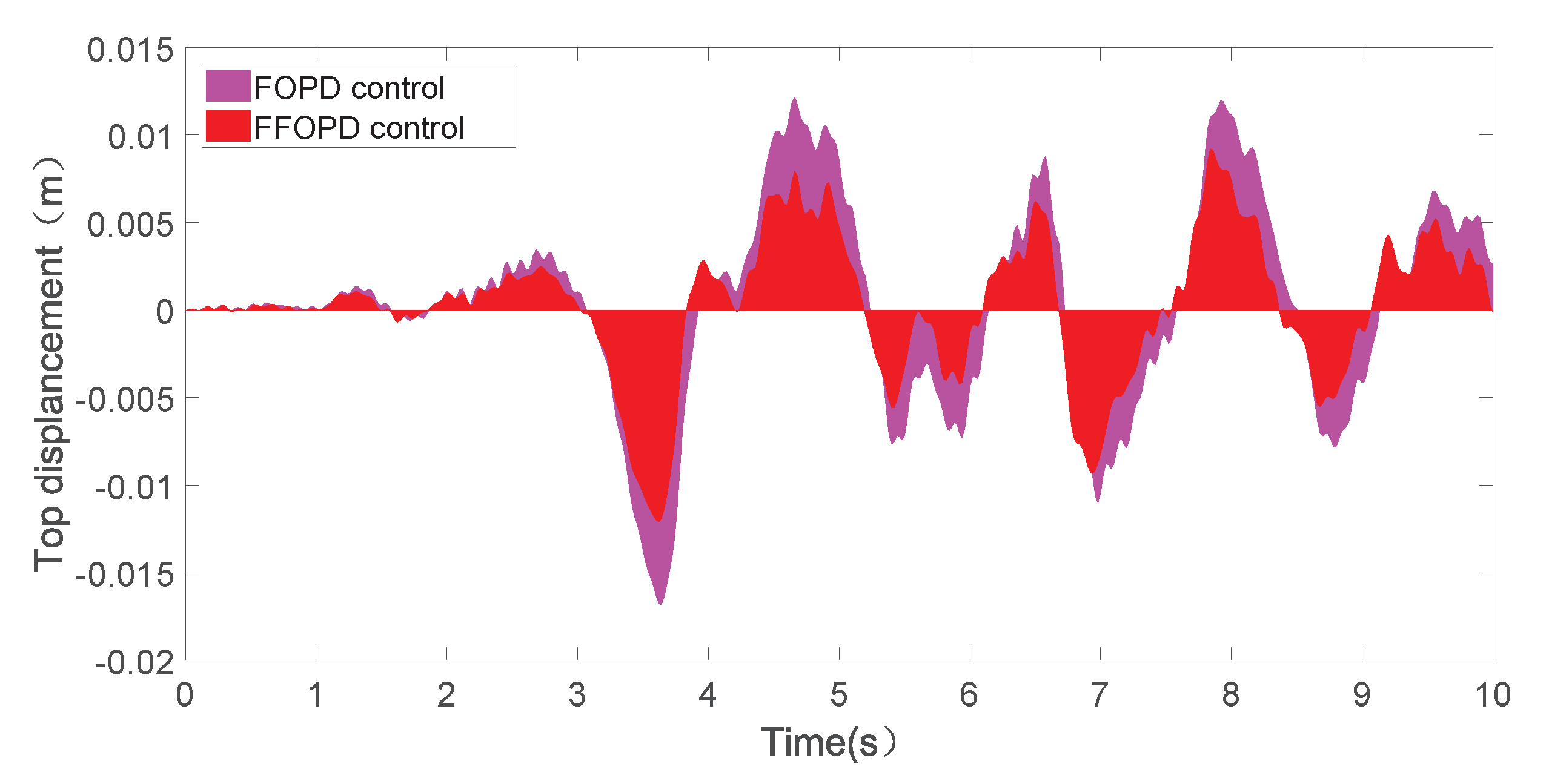
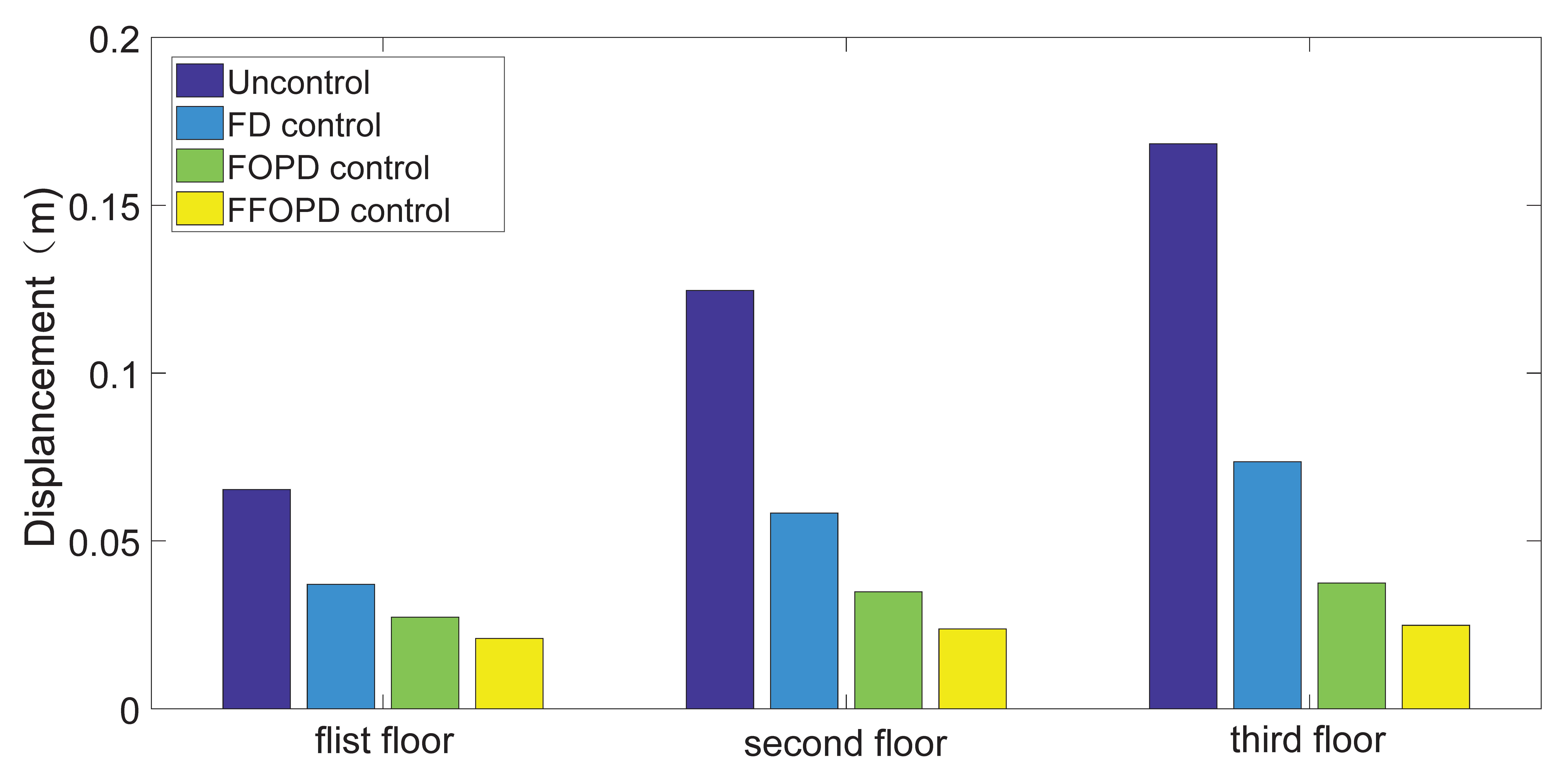
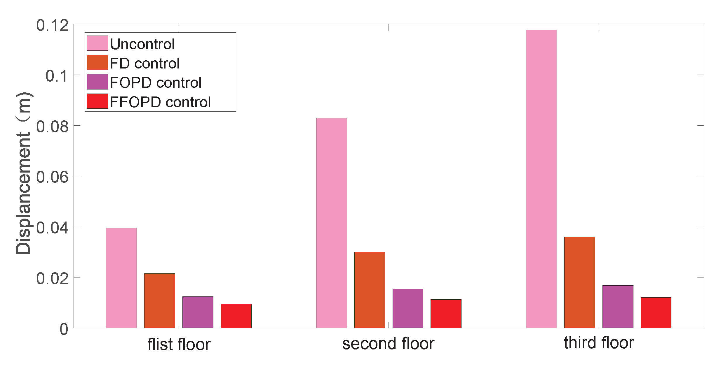
With different control cases, namely uncontrolled, PD, FOPD, and FFOPD control, the top floor displacement of the three-storey building under the seismic El-Centro and Taft earthquakes are shown in Figure 13 and Figure 14, respectively. The top displacement curve using the FOPD and FFOPD controller under the El-Centro and Taft earthquakes are depicted in Figure 15 and Figure 16, respectively. The maximum displacement of each floor under the El-Centro earthquake and Taft earthquake are shown in Figure 17 and Figure 18, respectively.
From Figure 13 and Figure 14, we verify that the FOPD and FFOPD yield excellent performance under the two different seismic waves. Compared with the PD, the FOPD controller has one more adjustable parameter, namely the fractional derivative order, μ , that can be selected arbitrarily. This widens the setting range of the controller parameters and leads to greater flexibility and better performance.
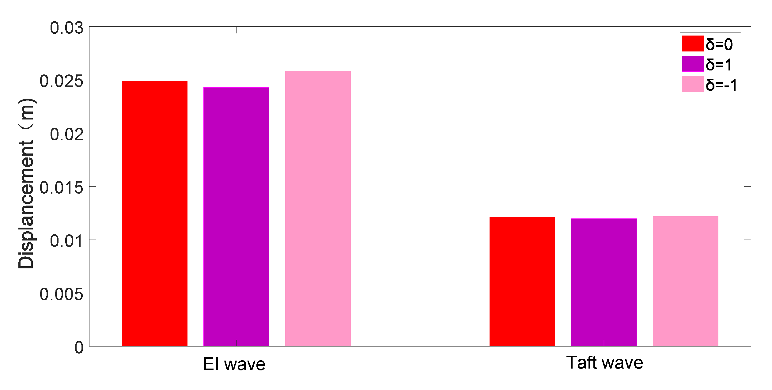
Indeed, from Figure 15, Figure 16, Figure 17 and Figure 18, the top floor maximum displacements obtained with the FOPD are 0.0375 m and 0.0168 m, and the average displacements are 0.0098 m and 0.0042 m. For the FFOPD, the maximum displacements are 0.0249 m and 0.0121 m, and the average displacements are 0.0069 m and 0.0028 m. The top floor maximum displacements for the FFOPD, when compared to the FOPD, are reduced by 50.6% and 38.8%, while the averaged displacements are reduced by 42.1% and 50%, respectively. It is obvious that the performance of FFOPD is superior to that of the FOPD.
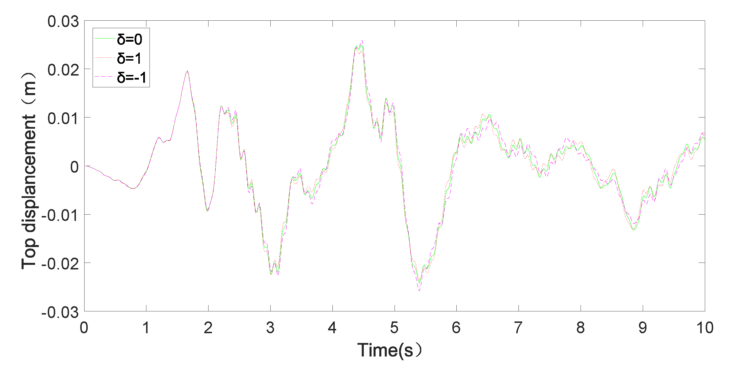
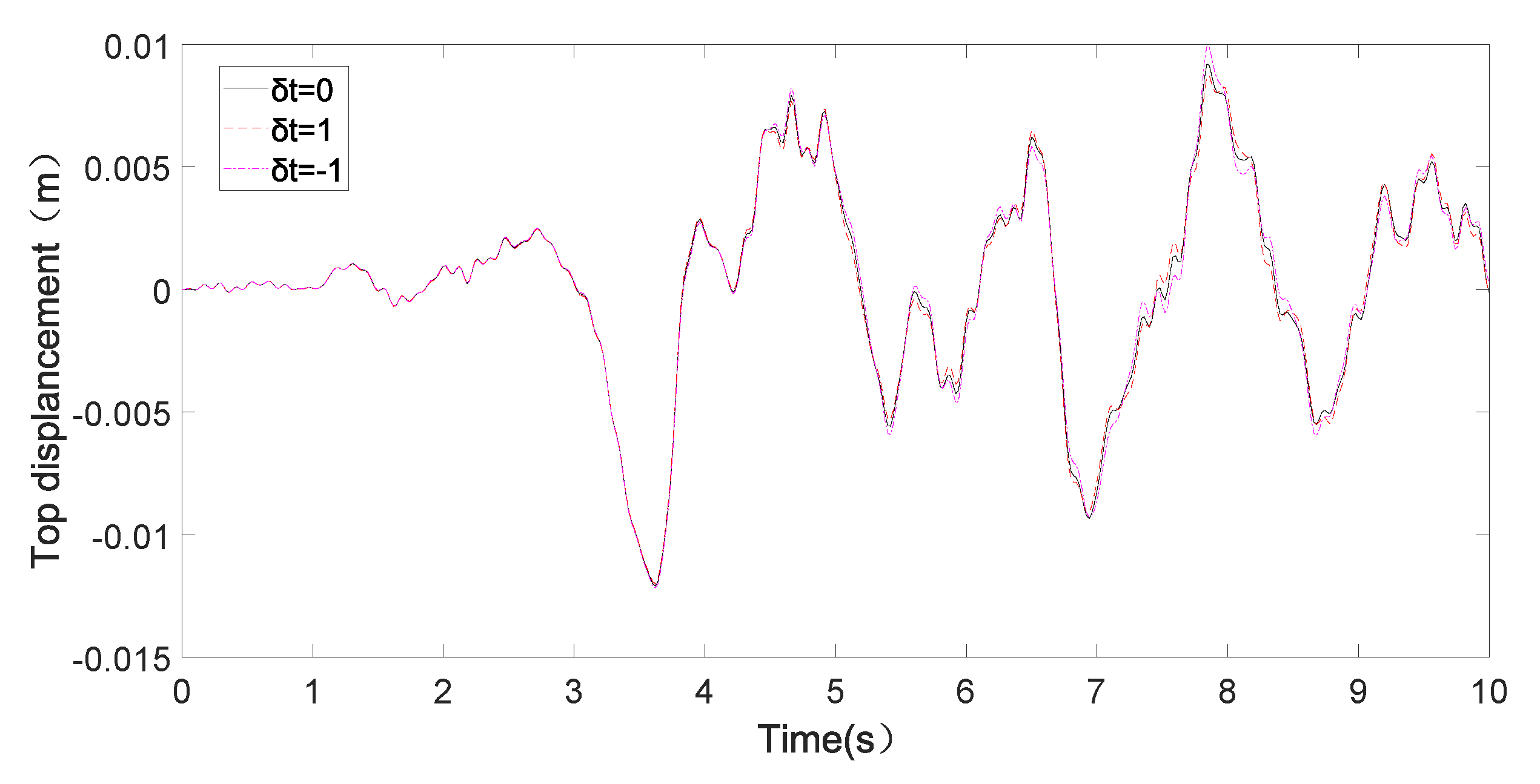
To show the robustness of the FFPOD controller, some comparative performance tests are carried out. When the uncertain parameter δ t is selected as 1 , 1 , the displacement responses of the third floor for the uncertain building structure are depicted in Figure 19 and Figure 20, for the El-Centro and Taft earthquake, respectively. We verify that the maximum displacement changed little, which is almost the same as what occurred in the deterministic parameters case.Figure 21 depicts the maximum displacements on the top floor, confirming the observations. Therefore, we can conclude that the FFOPD has superior performance and good robustness to uncertain structures.

5. Conclusions

A new vibration control strategy for uncertain building structures was proposed in this paper. Firstly, a new IFOPSO algorithm was introduced for the optimization of the initial parameters of a FOPD controller. Then, a novel FFOPD controller was designed to adapt the FOPD controller parameters on-line, and to ensure that they are always optimal. Finally, some simulations were carried out for the uncertain system and unknown seismic waves. The results proved that the proposed controller can obtain excellent robustness and superior effectiveness for structural vibration control.

Author Contributions

Methodology, L.C.; software, X.Z.; validation and data curation, M.W.; writing—original draft preparation, K.X.; writing—review and editing, A.M.L.; supervision and project administration, T.C. All authors have read and agreed to the published version of the manuscript.

Funding

This work was supported by the National Natural Science Foundation of China (No. 62073114; 11971032), Fundamental Research Funds for the Central Universities (No. JZ2022HGTA0320) and the Natural Science Foundation of Anhui Province (No. 2008085QE239).

Institutional Review Board Statement

Not applicable.

Informed Consent Statement

Not applicable.

Data Availability Statement

Not applicable.

Conflicts of Interest

The authors declare no conflict of interest.

References

  1. Gu, H.; Liang, H.; Tong, G.; Liu, F.; Liu, Y.; Liu, X.; Jia, Z.; Paul, J. Research on vibration mechanism and control technology of building structure under earthquake action. J. Vibroeng. 2021, 23, 1395–1406. [Google Scholar]
  2. Huang, J.; Rao, Y.; Qiu, H.; Lei, Y. Generalized algorithms for the identification of seismic ground excitations to building structures based on generalized Kalman filtering under unknown input. Adv. Struct. Eng. 2020, 23, 2163–2173. [Google Scholar] [CrossRef]
  3. He, Q.; Yin, A.; Fan, Z.; He, L. Seismic responses analysis of multi-story suspended floors system. J. Vibroeng. 2021, 23, 167–182. [Google Scholar] [CrossRef]
  4. Maruani, J.; Bruant, I.; Pablo, F.; Gallimard, L. Active vibration control of a smart functionally graded piezoelectric material plate using an adaptive fuzzy controller strategy. J. Intell. Mater. Syst. Struct. 2019, 30, 2065–2078. [Google Scholar] [CrossRef]
  5. Hu, W.; Gao, Y.; Yang, B. Semi-active vibration control of two flexible plates using an innovative joint mechanism. Mech. Syst. Signal Process. 2019, 130, 565–584. [Google Scholar] [CrossRef]
  6. Yang, X.; Gao, J. Linear–quadratic uncertain differential game with application to resource extraction problem. IEEE Trans. Fuzzy Syst. 2015, 24, 819–826. [Google Scholar] [CrossRef]
  7. Guo, S.X.; Li, Y. Non-probabilistic reliability method and reliability-based optimal LQR design for vibration control of structures with uncertain-but-bounded parameters. Acta Mech. Sin. 2013, 29, 864–874. [Google Scholar] [CrossRef]
  8. Zhang, X.Y.; Zhang, S.Q.; Wang, Z.X.; Qin, X.S.; Wang, R.X.; Schmidt, R. Disturbance rejection control with H optimized observer for vibration suppression of piezoelectric smart structures. Mech. Ind. 2019, 20, 202. [Google Scholar] [CrossRef]
  9. Wang, C.; Zhou, X.; Shi, X.; Jin, Y. Variable fractional order sliding mode control for seismic vibration suppression of uncertain building structure. J. Vib. Eng. Technol. 2021, 10, 299–312. [Google Scholar] [CrossRef]
  10. Kumar, G.; Kumar, A.; Jakka, R.S. The Particle Swarm modified quasi bang-bang controller for seismic vibration control. Ocean. Eng. 2018, 166, 105–116. [Google Scholar] [CrossRef]
  11. Paul, S.; Yu, W.; Li, X. Bidirectional active control of structures with type-2 fuzzy PD and PID. Int. J. Syst. Sci. 2018, 49, 766–782. [Google Scholar] [CrossRef]
  12. Zizouni, K.; Fali, L.; Sadek, Y.; Bousserhane, I.K. Neural network control for earthquake structural vibration reduction using MRD. Front. Struct. Civ. Eng. 2019, 13, 1171–1182. [Google Scholar] [CrossRef]
  13. Ma, T.; Bi, F.; Wang, X.; Tian, C.; Lin, J.; Wang, J.; Pang, G.; Sciubba, E. Optimized fuzzy skyhook control for semi-active vehicle suspension with new inverse model of magnetorheological fluid damper. Energies 2021, 14, 1674. [Google Scholar] [CrossRef]
  14. Metered, H.; Elsawaf, A.; Vampola, T.; Sika, Z. Vibration control of MR-damped vehicle suspension system using PID controller tuned by particle swarm optimization. SAE Int. J. Passeng. Cars-Mech. Syst. 2015, 8, 426–435. [Google Scholar] [CrossRef]
  15. Jin, X.; Chen, K.; Zhao, Y.; Ji, J.; Jing, P. Simulation of hydraulic transplanting robot control system based on fuzzy PID controller. Measurement 2020, 164, 108023. [Google Scholar] [CrossRef]
  16. Ab Talib, M.H.; Mat Darus, I.Z.; Mohd Samin, P.; Mohd Yatim, H.; Ardani, M.I.; Shaharuddin, N.M.R.; Hadi, M.S. Vibration control of semi-active suspension system using PID controller with advanced firefly algorithm and particle swarm optimization. J. Ambient. Intell. Humaniz. Comput. 2021, 12, 1119–1137. [Google Scholar] [CrossRef]
  17. Das, S.; Pan, I.; Das, S.; Gupta, A. A novel fractional order fuzzy PID controller and its optimal time domain tuning based on integral performance indices. Eng. Appl. Artif. Intell. 2012, 25, 430–442. [Google Scholar] [CrossRef]
  18. Etedali, S.; Zamani, A.A.; Tavakoli, S. A GBMO-based PIλDμ controller for vibration mitigation of seismic-excited structures. Autom. Constr. 2018, 87, 1–12. [Google Scholar] [CrossRef]
  19. Xiao, M.; Tao, B.; Zheng, W.X.; Jiang, G. Fractional-order PID controller synthesis for bifurcation of fractional-order small-world networks. IEEE Trans. Syst. Man Cybern. Syst. 2019, 51, 4334–4346. [Google Scholar] [CrossRef]
  20. Chen, P.; Luo, Y. A two-degree-of-freedom controller design satisfying separation principle with fractional-order PD and generalized ESO. IEEE/ASME Trans. Mechatronics 2021, 27, 137–148. [Google Scholar] [CrossRef]
  21. Tepljakov, A.; Gonzalez, E.A.; Petlenkov, E.; Belikov, J.; Monje, C.A.; Petráš, I. Incorporation of fractional-order dynamics into an existing PI/PID DC motor control loop. ISA Trans. 2016, 60, 262–273. [Google Scholar] [CrossRef] [PubMed]
  22. Munoz, J.; Monje, C.A.; Santiago, M.; Balaguer, C. Joint position control based on fractional-order PD and PI controllers for the arm of the humanoid robot TEO. Int. J. Humanoid Robot. 2019, 16, 1950042. [Google Scholar] [CrossRef]
  23. Xu, K.; Chen, L.; Wang, M.; Lopes, A.M.; Tenreiro Machado, J.; Zhai, H. Improved decentralized fractional PD control of structure vibrations. Mathematics 2020, 8, 326. [Google Scholar] [CrossRef]
  24. Liu, L.; Zhang, L.; Pan, G.; Zhang, S. Robust yaw control of autonomous underwater vehicle based on fractional-order PID controller. Ocean. Eng. 2022, 257, 111493. [Google Scholar] [CrossRef]
  25. Chen, L.; Chen, G.; Wu, R.; Lopes, A.M.; Tenreiro Machado, J.A.; Niu, H. Variable coefficient fractional-order PID controller and its application to a SEPIC device. IET Control Theory Appl. 2020, 14, 900–908. [Google Scholar] [CrossRef]
  26. Al-Dhaifallah, M.; Kanagaraj, N.; Nisar, K. Fuzzy fractional-order PID controller for fractional model of pneumatic pressure system. Math. Probl. Eng. 2018, 2018, 5478781. [Google Scholar] [CrossRef]
  27. Swethamarai, P.; Lakshmi, P. Adaptive-fuzzy fractional order PID controller-based active suspension for vibration control. IETE J. Res. 2020, 1–16. [Google Scholar] [CrossRef]
  28. Das, S.; Pan, I.; Das, S.; Gupta, A. Improved model reduction and tuning of fractional-order PIλDμ controllers for analytical rule extraction with genetic programming. ISA Trans. 2012, 51, 237–261. [Google Scholar] [CrossRef]
  29. Wang, J.; Huang, Y.; Wang, T.; Zhang, C.; Liu, Y.H. Fuzzy finite-time stable compensation control for a building structural vibration system with actuator failures. Appl. Soft Comput. 2020, 93, 106372. [Google Scholar]
  30. Li, Z.; Ding, J.; Wu, M.; Lin, J. Discrete fractional order PID controller design for nonlinear systems. Int. J. Syst. Sci. 2021, 52, 3206–3213. [Google Scholar] [CrossRef]
  31. Lavassani, S.H.H.; Shangapour, S.; Homami, P.; Gharehbaghi, V.; Farsangi, E.N.; Yang, T. An innovative methodology for hybrid vibration control (MR+ TMD) of buildings under seismic excitations. Soil Dyn. Earthq. Eng. 2022, 155, 107175. [Google Scholar] [CrossRef]
  32. Soleymani, M.; Abolmasoumi, A.H.; Bahrami, H.; Khalatbari-S, A.; Khoshbin, E.; Sayahi, S. Modified sliding mode control of a seismic active mass damper system considering model uncertainties and input time delay. J. Vib. Control 2018, 24, 1051–1064. [Google Scholar] [CrossRef]
  33. El Ouni, M.H.; Kahla, N.B.; Ahmed, M.; Islam, S.; Ayed, H.; Khedher, K.M. Comparative study of different active control systems of high rise buildings under seismic excitation. Period. Polytech. Civ. Eng. 2019, 63, 1092–1102. [Google Scholar] [CrossRef]
  34. Eberhart, R.; Kennedy, J. A new optimizer using particle swarm theory. In Proceedings of the Sixth International Symposium on Micro Machine and Human Science, Nagoya, Japan, 4–6 October 1995; pp. 39–43. [Google Scholar]
  35. Pires, E.; Machado, J.; Oliveira, P.; Cunha, J.B.; Mendes, L. Particle swarm optimization with fractional-order velocity. Nonlinear Dyn. 2010, 61, 295–301. [Google Scholar] [CrossRef]
  36. Yang, P.Y.; Chou, F.I.; Tsai, J.T.; Chou, J.H. Adaptive-uniform-experimental-design-based fractional-order particle swarm optimizer with non-linear time-varying evolution. Appl. Sci. 2019, 9, 5537. [Google Scholar] [CrossRef]
  37. Liu, L.; Pan, F.; Xue, D. Variable-order fuzzy fractional PID controller. ISA Trans. 2015, 55, 227–233. [Google Scholar] [CrossRef]
  38. Oussama, M.; Abdelghani, C.; Lakhdar, C. Efficiency and robustness of type-2 fractional fuzzy PID design using salps swarm algorithm for a wind turbine control under uncertainty. ISA Trans. 2022, 125, 72–84. [Google Scholar] [CrossRef]
Figure 1. Vibration control system of uncertain building structures.
Fractalfract 06 00473 g001
Figure 2. The n-DOF shear frame equipped with an ABS between the ground and the first floor.
Fractalfract 06 00473 g002
Figure 3. Flowchart of the IFOPSO algorithm for determining the parameters of the FOPD controller.
Fractalfract 06 00473 g003
Figure 4. Earthquake seismic wave with maximum amplitude adjusted to 4 m/s 2 .
Fractalfract 06 00473 g004
Figure 5. Top displacement versus time for the three algorithms under earthquake seismic wave excitation.
Fractalfract 06 00473 g005
Figure 6. Maximum displacement for the three algorithms under earthquake seismic wave excitation.
Fractalfract 06 00473 g006
Figure 7. Control system using the FFOPD under uncertain building structure.
Fractalfract 06 00473 g007
Figure 8. Membership function curve of various e and Δ K p .
Fractalfract 06 00473 g008
Figure 9. Membership function curve of various e c and Δ K d .
Fractalfract 06 00473 g009
Figure 10. Membership function curve of various Δ r 1 and Δ r 2 .
Fractalfract 06 00473 g010
Figure 11. Membership function curve of various Δ μ .
Fractalfract 06 00473 g011
Figure 12. A three-storey building structure with actuators.
Fractalfract 06 00473 g012
Figure 13. Top floor displacement curve under El-Centro earthquake.
Fractalfract 06 00473 g013
Figure 14. Top floor displacement curve under Taft earthquake.
Fractalfract 06 00473 g014
Figure 15. Top displacement curve for FOPD and FFOPD under El-Centro earthquake.
Fractalfract 06 00473 g015
Figure 16. Top displacement curve for FOPD and FFOPD under Taft earthquake.
Fractalfract 06 00473 g016
Figure 17. Maximum displacement of each floor under El-Centro earthquake.
Fractalfract 06 00473 g017
Figure 18. Maximum displacement of each floor under Taft earthquake.
Fractalfract 06 00473 g018
Figure 19. Top floor displacement curve of the uncertain structure under the El-Centro wave.
Fractalfract 06 00473 g019
Figure 20. Top floor displacement curve of the uncertain structure under the Taft wave.
Fractalfract 06 00473 g020
Figure 21. Maximum displacement from top floor of uncertain structure.
Fractalfract 06 00473 g021
Table 1. The FOPD parameters generated by the PSO, FOPSO, and IFOPSO algorithms.
Range [ K p , K d , μ ] = [ 0 20 , 0 5 , 0 2 ]
Name of the Optimization AlgorithmControl System Parameter Value
FOPD-PSO [ K p , K d , μ ] = [ 8.43 , 3.89 , 1.61 ]
FOPD-FOPSO [ K p , K d , μ ] = [ 14.92 , 4.51 , 1.65 ]
FOPD-IFOPSO [ K p , K d , μ ] = [ 19.48 , 4.93 , 1.63 ]
Table 2. Structural parameters of the uncertain building.
Floor123
Height (m)3.23.03.0
Quality (kg)276227602300
Rigidity ( 1 × 10 5  N/m)2.4851.9211.522
Name of VariousParameter Values
uncertain parameters α = 0.1 β = 0.15 γ = 0.15
various of δ t δ t = 0 δ t = 1 δ t = 1
various of H ( t ) H T ( t ) H ( t ) I
Table 3. Fuzzy logic control parameters.
Variables of Fuzzy AlgorithmFuzzy Logic Parameter Value
Fuzzy domain variables (input) e [ 4 , 4 ] ; e c [ 3 , 3 ]
Fuzzy domain variables (output) Δ K p [ 4 , 4 ] ; Δ K d [ 3 , 3 ]
Δ μ [ 0.2 , 0 ] ; Δ r 1 [ 1.1 , 1.4 ] ; Δ r 2 [ 1 , 1.3 ]
Input quantization factors K e = 100 ; K e c = 10
Output proportion factors K = 1
Table 4. Fuzzy control rule of ( Δ K p , r 1 )/( Δ K d , r 2 ).
ec
eNBNMNSZPSPMPB
NBPB/PSPB/NSPM/NBPM/NBPS/NBZ/NMZ/PS
NMPB/PSPB/NSPM/NBPS/NMPS/NMZ/NSNS/Z
NSPM/ZPM/PSPM/PMPS/PMZ/PSNS/PSNS/Z
ZPM/ZPM/NSPS/NSZ/NSNS/NSNM/NSNM/Z
PSPS/ZPS/ZZ/ZNS/ZNS/ZNM/ZNM/Z
PMPS/PBZ/PSNS/PSNM/PSNM/PSNM/PSNB/PB
PBZ/PBZ/PMNM/PMNM/PMNM/PSNB/PSNB/PB
Table 5. Fuzzy control rule of Δ μ .
ec
eNBNMNSZPSPMPB
NBNSPSPBPBPBPMNS
NMPSPSPBPMPMPSZ
NSZNSNMNMNSNSZ
ZZPSPSPSPSPSZ
PSZZZZZZZ
PMNBNSNSNSNSNSNM
PBNBNMNMNMNSNSNB
Table 6. Control system parameters.
Name of the IFOPSO ParametersValue of the Parameters
Particle number N = 50
Number of iterations/Repeated experiments T = 200 / E = 40
Scaling factors c 1 = c 2 = 2 , υ m i n = 1 , υ m a x = 1 , ω i =
Range [ K p , K d , μ ] = [ 0 20 , 0 5 , 0 2 ]
Name of the Control SystemControl System Parameter Value
PD [ K p , K d ] = [ 0.02 , 3.75 ]
FOPD [ K p , K d , μ ] = [ 19.48 , 4.93 , 1.63 ]
FFOPD [ K p , K d , μ , r 1 , r 2 ] = [ , , , , ]
Note: the symbol ∼ means that the value changes with time.
Publisher’s Note: MDPI stays neutral with regard to jurisdictional claims in published maps and institutional affiliations.