Abstract
In the present work, the q-homotopy analysis transform method (q-HATM) was used to generate an analytical solution for the moisture content distribution in a one-dimensional vertical groundwater recharge problem. Three scenarios for the Brooks–Corey model are studied based on linear and nonlinear diffusivity and conductivity functions. The governing nonlinear fractional partial differential equations are solved effectively by the combination of a hybrid analytical technique, which is the combination of the q-homotopy analysis method and the Laplace transform method. Figures and tables are used to discuss the outcomes for fractional values of the time derivative. Mathematica software is used to plot the figures. The examples used in this paper demonstrate the accuracy and competence of the considered algorithm. The acquired results demonstrate the efficiency and reliability of the projected scheme and are also suitable to carry out the highly nonlinear complex problems in a real-world scenario.
1. Introduction
Fractional calculus is a branch of mathematics that begins from typical definitions of calculus integral and derivative operators, much like fractional exponents emerge from integer exponents. Fractional calculus (fractional derivatives and fractional integrals) is a well-known notion. In 1695, L’Hospital enquired about the significance of if n = 1/2, if n = 1/2, or “‘how about if n is fractional?’ will be equivalent to ,” Leibniz said.
The physical and geometric meanings of integer-order derivatives and integrals are well known. Unfortunately, this is not true in the case of fractional-order integration and differentiation, which is a fast-growing topic in both theoretical and practical aspects to real-world situations. Many books and articles have been written to document this [1,2,3,4,5,6,7,8,9,10]. For more than 300 years, there has been no admissible geometric or physical description of differentiation and integration of arbitrary (i.e., not necessarily an integer) order. The geometric meaning of fractional integration is “Shadows on the walls”, while the physical meaning is “Shadows of the past”, as seen in Ref. [11]. Fractional operators can depict certain phenomena better than regular derivatives and integrals and can characterize systems with high-order dynamics and complicated nonlinear occurrences more effectively. This serves two purposes. First, instead of being constrained to integer-order, we can choose any order for the derivative and integral operators. Second, fractional order derivatives are advantageous when the system has a long-term memory, as they are dependent not only on local but also on historical conditions.
The approximate numerical solution of most nonlinear FDEs necessitates the use of numerical schemes. Modelling the dimensions of equations is not the only factor to consider; the dependability of solution techniques is also crucial [12,13]. The homotopy analysis method (HAM) [14] is an analytical approach with an embedding parameter , which is then improved as q-HAM with . With the term in the series, the solution achieves faster convergence than HAM. To study complex nonlinear issues with minimal CPU time, the connectedness of an analytical approach with a transform [15,16] is critical. As a result of combining the q-HAM and the Laplace transform, the q-HATM (see [17,18,19]) is an excellent analytical method. It has the advantage of being able to incorporate powerful computational approaches for investigating FDEs. By properly selecting , it offers an easy technique to regulate the convergence area of the series solution in a wider permitted zone. For the similar grid point and sequence of the series solution, it produces more acceptable results. H and n-curves demonstrate the validity of a solution in the convergent zone. The q-HATM has the advantages of not requiring linearization, perturbations, discretization, or any restrictive constraints, significantly reducing mathematical calculations, promising a large convergence province, providing a non-local influence, and not requiring the computation of complex polynomials, integrations, or physical parameters.
The phenomenon of the model is schematically shown in Figure 1, where different conditions, mechanisms, and major pathways for contaminant transport may vary in the saturated and unsaturated zone. The subterranean environment, which lies between the groundwater and the land surface, is included in the unsaturated zone. The unsaturated zone is the first subterranean habitat to be impacted by pollutants generated by human activity. The existence of a gas–water interface, oxygen, comparatively high microbial activity, and large amounts of particulate organic matter characterize the unsaturated zone in general. Chemical conditions fluctuate significantly with place and time due to dilution through concentration or rainwater, evaporation, and large vertical and horizontal variations in the solid phase composition. Contaminant transportation in the unsaturated zone will be vertical. Generally, the saturated zone is characterized by much lower oxygen content, much lower organic matter contents, and a lesser absorption capacity of the solid phase. Chemical circumstances in the unsaturated zone, on the other hand, will be less variable in space and time as the impact of evapotranspiration and dilution will be minimal. Contaminant transportation will be mainly horizontal in the saturated zone and is important for the transport of inorganic contaminants. The water saturates almost all fractures and holes in the saturated zone. The pore space in the unsaturated zone is partially filled by water and partially by air. The subsurface between the groundwater table and the ground surface is part of the unsaturated zone.
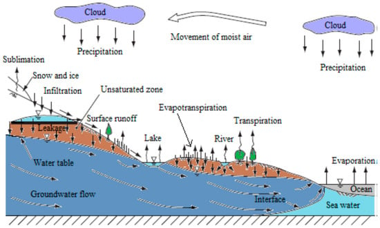
Figure 1.
The hydrological cycle.
In unsaturated subsurface environments, there are three phases: water, gas, and solid. Gas is one of the major phases. These are mainly two interfaces, the solid–water and the gas–water interfaces.
In saturated porous media, there are two mechanisms that control colloid retention: one is an attachment at mechanical straining and another is the solid–water interface (SWI). Additional colloid retention in unsaturated porous media may take place at air–water interfaces (AWI) and air–water–solid (AWS) interfaces. Patil and Chore [20] investigated the transport of pollutants through porous media. The review includes the investigation concerning both unsaturated and saturated porous media. Raji et al. [21] demonstrated the pollutant flow, mass transport, and the technologies that can be applied to define the pollutants’ behavior in the saturated and unsaturated soil zones. Sen [22] examined the processes in bio colloidal pollutants in unsaturated and saturated porous media. Xu et al. [23] studied unfavorable conditions, especially in the high ionic strength solutions, and found that steady solid phase could be more important than air phase in determining colloid retention in unsaturated porous media.
The present study is organized as follows: prefaces to the Laplace Transform (LT), fractional derivative in the Caputo sense, and the Reimann–Liouville fractional integral are covered in Section 2. Section 3 presents the mathematical formulation of Richard’s equation. Section 4 deals with different forms of nonlinear Richard’s equation based on the Brooks–Corey model. Section 5 presents the core concept of the proposed technique, whereas Section 6 discusses the solutions that can be achieved utilizing the technique in consideration. In the perspective of plots, the reaction and type of the produced results concern fractional order. The final section contains comments on the findings obtained.
2. Research Basics Definitions
The basic definitions of the LT, as well as the fractional calculus (FC), are included in the current section of the article, which will be portrayed in the following framework:
Definition 1.
The fractional kind integral of a non-zero positive order function, delineated by Reimann–Liouville, is represented by:
Definition 2.
The Caputo–Liouville fractional derivative of is differentiated as:
Definition 3.
The Laplace transform of a Caputo fractional derivativeis represented in the following way:
wheredenotes the LT of the function.
3. Mathematical Formulation
The flow of water through an unsaturated porous medium is given by the governing equation as follows:
where is the fluid density, U is the moisture content at any depth x, and M is a mass flux of moisture.
The motion of the water in an unsaturated porous medium is articulated using Darcy’s law as follows [24]:
where the whole moisture potential is indicated by ∇ϕ, k indicates the hydraulic conductivity, and v is the volume flux of moisture.
As , Equations (4) and (5) lead to:
As the flow occurs only in one direction (vertically), consider , with as the pressure potential. The x-axis is presumed to be positive in the vertical descending direction. Equation (6) falls to:
Assume that represents soil water diffusivity and and are related by single-valued function. Furthermore, we substitute the value of D in Equation (7), which can be read as:
Equation (8) represents the water content in an unsaturated porous medium known as Richard’s equation with many applications in soil sciences, engineering, and hydrology.
4. Discussions
In the present study, we have considered the nonlinear Richard’s Equation (8) for linear and nonlinear conductivity and diffusivity coefficients. Let and with be conductivity and diffusivity, respectively, in the Brooks–Corey model [25,26,27]. The Brooks–Corey model was described in this paper with three scenarios: (i) Nonlinear conductivity and linear diffusivity; (ii) Linear conductivity and linear diffusivity; and (iii) Linear conductivity and nonlinear diffusivity.
4.1. Linear Diffusivity and Nonlinear Conductivity
The term diffusivity is taken to be constant as and [15], and using the dimensionless variables and , then Equation (8) reduces to the following governing equation:
4.2. Linear Diffusivity and Linear Conductivity
In this case, both and express as linear functions of , i.e., and [15], and using the dimensionless variables and , then Equation (8) reduces to the following governing equation:
4.3. Non-Linear Diffusivity and Linear Conductivity
In this case, expresses as a nonlinear function of , i.e., and express as a linear function of ., i.e., ([15], Volume 9) and using the dimensionless variables and . Then, Equation (8) reduces to the following governing equation:
At a depth z and time t, the solutions of Equations (9)–(11) represent the moisture content of the soil. The boundary conditions are chosen in such a way that the flow of water will be in the vertically downward direction.
The above three cases of Richard’s equation are presented in terms of nonlinear fractional-order partial differential equations as follows:
where represents the Caputo–Liouville fractional derivative (C-LFD) of the function and is the fractional order such that .
5. The Basic Concept of the q-HATM
The idea of the considered scheme [14] can be well explained by considering the general non-homogeneous nonlinear PDE of the form:
where is the C-FD of the and is the source term.
Currently, hiring the LT on Equation (15) leads to:
After simplifying, Equation (16) reduces to:
The nonlinear useful operator , is differentiated as follows:
where called the Laplace transform and is the function of and .
The homotopy involving is defined as follows:
where corresponds an initial estimate of , is an auxiliary parameter. The following recommended outcomes are true for and , respectively:
Therefore, by displacing from to , the solution changes from to . The series form representation of is mentioned as below:
where:
The series (21) converges at by selecting the precise values for and (auxiliary parameter) with proper initial guess and , the obtained series solution is of the form:
Then, divide by followed by differentiating Equation (19) times with respect to . Finally, we derive the deformation equation of order as follows for q = 0:
and considering the vectors, as follows:
The following recursive equation is obtained by employing the inverse on Equation (24):
where:
and:
Lastly, we find the required q-HATM series solution after solving Equation (26).
5.1. Solution Procedure for the First Case of Richard’s Equation
Consider the nonlinear fractional partial differential Equation (12) with linear diffusivity and nonlinear conductivity as follows:
along with the very first solution:
By using the LT on Equation (29) and then using Equation (30), we find:
The operator N (non-linear) is defined with the use of a future methodology and is expressed by:
Then, divide by m!, followed by differentiating Equation (29) m times with respect to q. Finally, we derive the deformation equation of order m as follows for q = 0:
where:
Hiring inverse LT on Equation (33), we find
We can see the following iterations from the constituent simplification of Equation (35):
This is how we arrive at the further iterative terms. Finally, Equation (29) yields a series solution, which is highlighted by:
By implementing , , and , the attained solution will close up with the analytical result as .
5.2. Solution Procedure for the Second Case of Richard’s Equation
Consider the nonlinear fractional partial differential Equation (13) with linear diffusivity and nonlinear conductivity as follows:
along with the very first solution:
By employing the LT on Equation (37) and then utilizing Equation (38), we find:
The operator N (non-linear), is defined with the use of a future methodology and is expressed by:
Then, divide by m! followed by differentiating Equation (37) m times with respect to q. Finally, we derive the deformation equation of order m as follows for q = 0:
where:
Now employing the ILT on Equation (41), we find:
We can have the following iterations from the constituent simplification of Equation (43):
This is how we find the most important iterative words. Finally, Equation (37) yields a series solution, which is highlighted by:
By implementing , , and , the accomplished result will close up with the analytical outcome as .
5.3. Solution Procedure for the Third Case of Richard’s Equation
Consider the nonlinear fractional partial differential Equation (14) with linear diffusivity and nonlinear conductivity as follows:
which is subject to the very first solution:
By applying the LT to Equation (45) and then using Equation (46), we find:
The operator N (non-linear) is defined as with the use of a future methodology and is expressed as:
Then, divide m! by differentiating Equation (45) m times with respect to q. Finally, we derive the deformation equation of order m as follows for q = 0:
where:
Now plugging the ILT on Equation (49), we find:
We can have the following iterations from the constituent simplification of Equation (51):
This is how we find the most important iterative words. Finally, Equation (4) yields a series solution which highlighted by:
By implementing , , and , the conquered result will close up with the analytical result as .
6. Numerical Results and Discussion
We performed numerical simulations for different forms of fractional Richard’s equation (Equations (12)–(14)) by using an adequate hybrid analytical technique, q-HATM. The graphs of obtained solutions are plotted for different values of α and t. Table 1, Table 2 and Table 3 depict the values of the moisture content U(x,t) for different values of x and t at n = 1, α = 1, and ℏ = −0.1. The surface plots of the moisture content versus depth x and time t for Equation (29) is presented in Figure 2. The 2D plots of the moisture content U(x,t) versus depth x for Equation (29) at various values of t and α are obtained and cited in Figure 3 and Figure 4. The plot of acquired solution versus auxiliary parameter is shown in Figure 5. Figure 6 shows that the U(x,t), for example (29), increases with increase in time . The density plot showing the moisture content distribution over the region is presented in Figure 7. The 3D plots of the moisture content versus depth x and time t for Equation (37) are presented in Figure 8. The 2D plots of the moisture content U(x,t) versus depth x for Equation (37) at various values of t and α are obtained and cited in Figure 9 and Figure 10. ℏ-curves with different fractional order , for example (37), are presented in Figure 11. Figure 12 shows that the U(x,t), for example (37), increases with increase in time for α = 1, 0.75, and 0.50. The density plot showing the moisture content distribution over the region is presented in Figure 13. The surface plots of the moisture content versus depth x and time t for Equation (45) is presented in Figure 14. The 2D plots of the moisture content U(x,t) versus depth x for Equation (45) at various values of t and α are obtained and cited in Figure 15 and Figure 16, respectively. ℏ-curves with different fractional order , for example (45), are presented in Figure 17. Figure 18 shows that the U(x,t), for example (45), increases with increase in time . The moisture content distribution over the region is represented by the density plot in Figure 19.

Table 1.
Numerical values of moisture content .

Table 2.
Numerical values of moisture content .

Table 3.
Numerical values of moisture content .
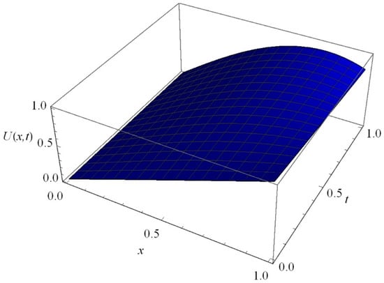
Figure 2.
The graph of versus depth and time for Equation (29).
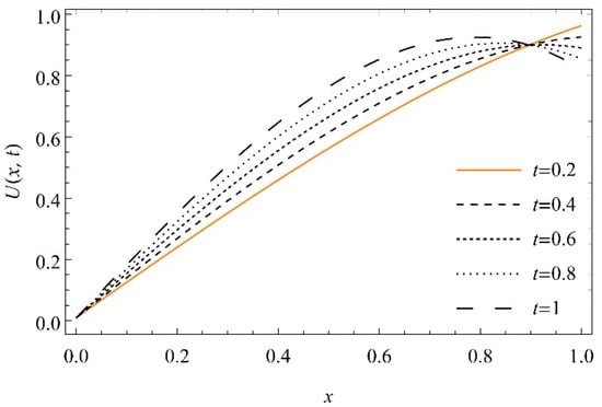
Figure 3.
The graph of versus depth x at , and for for Equation (29).
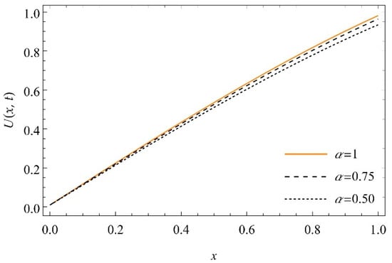
Figure 4.
The graph of versus depth at , and for for Equation (29).
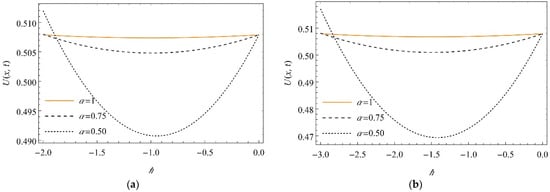
Figure 5.
The sketch of -curve profiles for the against for Equation (29) at (a) and (b) when for .
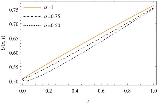
Figure 6.
The graph of versus time at , and for for Equation (29).
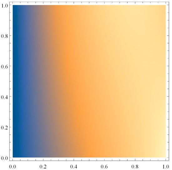
Figure 7.
Density graph of versus depth .
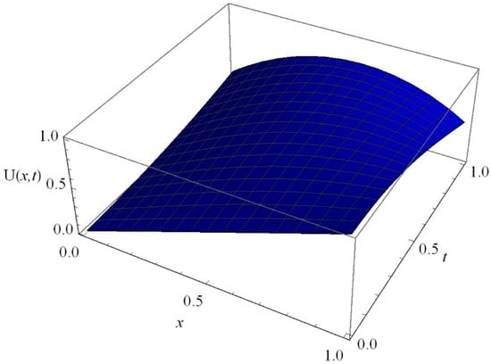
Figure 8.
The graph of versus depth and time for Equation (37).
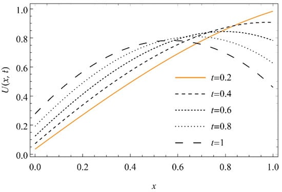
Figure 9.
The graph of versus depth x at , and for for Equation (37).
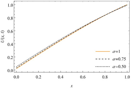
Figure 10.
The graph of versus depth at , and for for Equation (37).
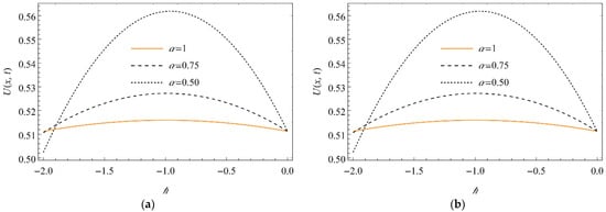
Figure 11.
The sketch of -curve profiles for the against for Equation (37) at (a) and (b) when for diverse values of .
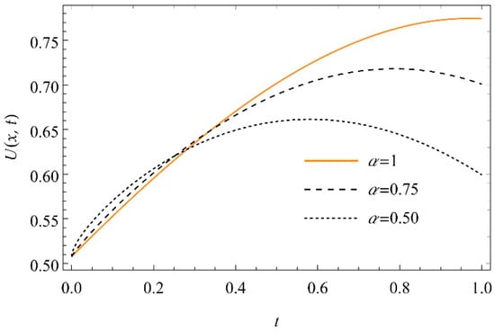
Figure 12.
The graph of versus time at , and for for Equation (37).
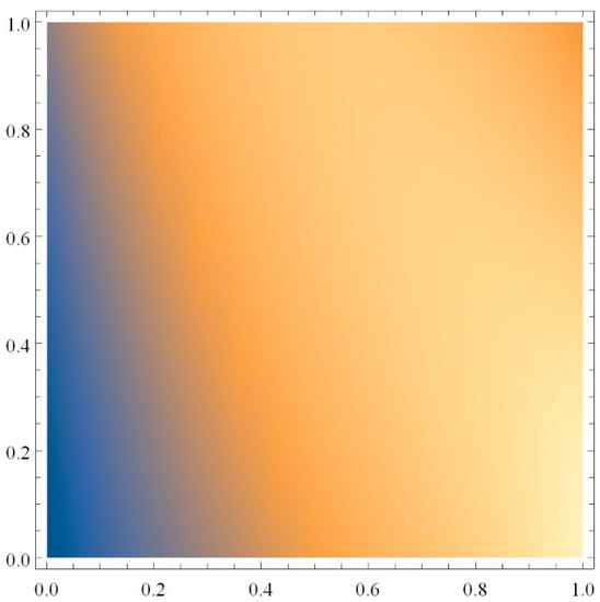
Figure 13.
Density graph of versus depth for Equation (37).
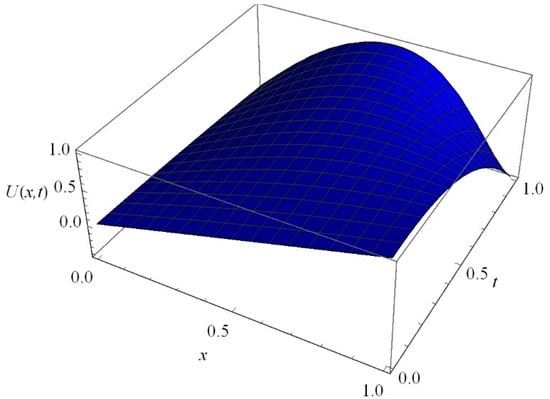
Figure 14.
The graph of versus depth and time for Equation (45).
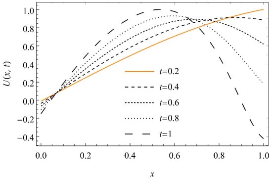
Figure 15.
The graph of versus depth x at , and for for Equation (45).
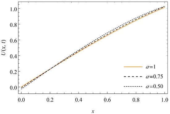
Figure 16.
The graph of versus depth at , and for for Equation (45).
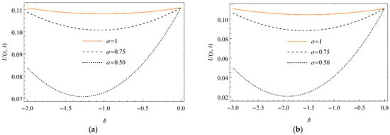
Figure 17.
The sketch of -curve for the against for considered Equation (45) at (a) and (b) when for sundry values of .
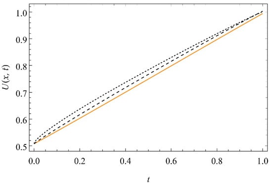
Figure 18.
The graph of versus time at , and for for Equation (45).
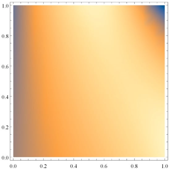
Figure 19.
Density graph of versus depth for Equation (45).
7. Conclusions
The one-dimensional groundwater recharge via spreading through an unsaturated porous medium was studied. The governing equations are solved using the q-homotopy analysis transform method. The equations, which are based on nonlinear and linear diffusivity and conductivity functions, are introduced, and their respective series solutions are obtained. The solutions are represented numerically and graphically. When the depth of the soil is increased for a period of time, the moisture content of the soil increases.
Author Contributions
Conceptualization, R.J.G. and S.S.; methodology, S.S.P., R.J.G. and S.S.; software, R.J.G. and U.K.; validation, R.J.G., U.K. and W.W.; formal analysis, S.S., S.S.P., A.Z. and W.W.; investigation, U.K., A.Z. and R.J.G.; resources, S.S. and W.W.; data curation, A.Z.; writing—original draft preparation, U.K., S.S., S.S.P. and W.W.; writing—review and editing, A.Z. and S.S.P.; visualization, A.Z., W.W. and U.K.; supervision, A.Z.; project administration, W.W.; and funding acquisition, W.W. All authors have read and agreed to the published version of the manuscript.
Funding
This research received funding support from the NSRF via the Program Management Unit for Human Resources & Institutional Development, Research and Innovation (grant number B05F640092).
Data Availability Statement
Not applicable.
Conflicts of Interest
The authors declare no conflict of interest.
References
- Samko, S.G.; Kilbas, A.A.; Marichev, O. Fractional Integrals and Derivatives: Theory and Applications; Gordon and Breach: Philadelphia, PA, USA, 1993. [Google Scholar]
- Kilbas, A.; Srivastava, H.M.; Trujillo, J.J. Theory and Applications of Fractional Differential Equations; Elsevier Science Limited: Amsterdam, The Netherlands, 2006. [Google Scholar]
- Zaslavsky, G. Hamiltonian Chaos and Fractional Dynamics; Oxford University Press: Oxford, UK, 2005. [Google Scholar]
- Baleanu, D.; Diethelm, K.; Scala, E.; Trujillo, J.J. Fractional Calculus: Models and Numerical Methods, Series on Complexity, Nonlinearity and Chaos; World Scientific Publishing Company: Singapore, 2012. [Google Scholar]
- Mainardi, F. Fractional Calculus and Waves in Linear Viscoelasticity: An Introduction to Mathematical Models; World Scientific Publishing Company: Singapore, 2010. [Google Scholar]
- Tarasov, V.E. Fractional Dynamics: Applications of Fractional Calculus to Dynamics of Particles, Fields and Media; Springer Science & Business Media: Berlin/Heidelberg, Germany, 2011. [Google Scholar]
- Ortigueira, M.D. Fractional Calculus for Scientists and Engineers; Springer Science & Business Media: Berlin/Heidelberg, Germany, 2011. [Google Scholar]
- Monje, C.A.; Chen, Y.Q.; Vinagre, B.M.; Xue, D.; Feliu-Batlle, V. Fractional Order Systems and Controls; Springer Science & Business Media: Berlin/Heidelberg, Germany, 2010. [Google Scholar]
- Hifler, R. Applications of Fractional Calculus in Physics; World Scientific: Singapore, 2000. [Google Scholar]
- Klages, R.; Radons, G.; Sokolov, I.M. Anomalous Transport: Foundations and Applications; Wiley-VCH: Weinheim, Germany, 2008. [Google Scholar]
- Podlubny, I. Fractional Differential Equations; Academic Press: Cambridge, MA, USA, 1999. [Google Scholar]
- Prakash, A.; Goyal, M.; Gupta, S. Fractional variational iteration method for solving time-fractional Newell-Whitehead-Segel equation. Nonlinear Eng. 2019, 8, 164–171. [Google Scholar] [CrossRef]
- Yokus, A.; Bulut, H. Numerical simulation of KdV equation by finite difference method. Indian J. Phys. 2018, 92, 1571–1575. [Google Scholar] [CrossRef]
- Liao, S. On the homotopy analysis method for nonlinear problems. Appl. Math. Comput. 2004, 147, 499–513. [Google Scholar] [CrossRef]
- Khan, M.; Gondal, M.A. Homotopy perturbation pade transform method for blasius flow equation using He’s polynomials. Int. J. Nonlinear Sci. Numer. Simul. 2011, 12, 1–7. [Google Scholar] [CrossRef]
- Liu, Z.J.; Adamu, M.Y.; Suleiman, E.; He, J.H. Hybridization of homotopy perturbation method and Laplace transformation for the partial differential equations. Therm. Sci. 2017, 21, 1843–1846. [Google Scholar] [CrossRef] [Green Version]
- Prakash, A.; Veeresha, P.; Prakasha, D.G.; Goyal, M. A homotopy technique for a fractional order multi-dimensional telegraph equation via the Laplace transform. Eur. Phys. J. Plus 2019, 134, 19. [Google Scholar] [CrossRef]
- Malagi, N.S.; Veeresha, P.; Prasannakumara, B.C.; Prasanna, G.D.; Prakasha, D.G. A new computational technique for the analytic treatment of time-fractional Emden Fowler equations. Math. Comput. Simul. 2021, 190, 362–376. [Google Scholar] [CrossRef]
- Prakasha, D.G.; Malagi, N.S.; Veeresha, P. New approach for fractional Schrödinger-Boussinesq equations with Mittag-Leffler kernel. Math. Meth. Appl. Sci. 2020, 43, 9654–9670. [Google Scholar] [CrossRef]
- Patil, S.B.; Chore, H.S. Contaminant transport through porous media: An overview of experimental and numerical studies. Adv. Environ. Res. 2014, 3, 45–69. [Google Scholar] [CrossRef] [Green Version]
- Raji, J.; Anitha, R.; Niranjan, C.M.; Sudheendra, S.R. Mathematical Solutions of Transport of Pollutants through Unsaturated Porous Media with Adsorption in a Finite Domain. January 2014. Available online: http://13.232.72.61:8080/jspui/handle/123456789/546 (accessed on 10 March 2022).
- Sen, T.K. Processes in Pathogenic Biocolloidal Contaminants Transport in Saturated and Unsaturated Porous Media: A Review. Water Air Soil Pollut. 2011, 216, 239–256. [Google Scholar] [CrossRef]
- Xu, S.; Qi, J.; Chen, X.; Lazouskaya, V.; Zhuang, J.; Jin, Y. Coupled effect of extended DLVO and capillary interactions on the retention and transport of colloids through unsaturated porous media. Sci. Total Environ. 2016, 573, 564–572. [Google Scholar] [CrossRef] [PubMed]
- Bear, J. Dynamics of Fluids in Porous Media; American Elasevier Publishing Co. Inc.: New York, NY, USA, 1972. [Google Scholar]
- Corey, A.T. Mechanics of Immiscible Fluids in Porous Media; Water Resources Publication: Fort Collins, CO, USA, 1994. [Google Scholar]
- Nasseri, M.; Daneshbod, Y.; Pirouz, M.D.; Rakshandehroo, G.R.; Shirzad, A. New analytical solution to water content simulation in porous media. J. Irrig. Drain. Eng. 2012, 138, 328–335. [Google Scholar] [CrossRef]
- Witelski, T. Motion of wetting fronts moving into partially pre-wet soil. Adv. Water Resour. 2005, 28, 1133–1141. [Google Scholar] [CrossRef]
Publisher’s Note: MDPI stays neutral with regard to jurisdictional claims in published maps and institutional affiliations. |
© 2022 by the authors. Licensee MDPI, Basel, Switzerland. This article is an open access article distributed under the terms and conditions of the Creative Commons Attribution (CC BY) license (https://creativecommons.org/licenses/by/4.0/).