Article

The Mittag-Leffler Function for Re-Evaluating the Chlorine Transport Model: Comparative Analysis

by
Abdulrahman F. Aljohani
1,
Abdelhalim Ebaid
1,*,
Ebrahem A. Algehyne
1,
Yussri M. Mahrous
2,
Carlo Cattani
3 and
Hind K. Al-Jeaid
4
1
Computational & Analytical Mathematics and Their Applications Research Group, Department of Mathematics, Faculty of Science, University of Tabuk, Tabuk 71491, Saudi Arabia
2
Department of Studies and Basic Sciences, Faculty of Community, University of Tabuk, Tabuk 71491, Saudi Arabia
3
Engineering School (DEIM), University of Tuscia, 01100 Viterbo, Italy
4
Department of Mathematical Sciences, Umm Al-Qura University, Makkah 21955, Saudi Arabia
*
Author to whom correspondence should be addressed.
Fractal Fract. 2022, 6(3), 125; https://doi.org/10.3390/fractalfract6030125
Submission received: 31 January 2022 / Revised: 9 February 2022 / Accepted: 12 February 2022 / Published: 22 February 2022
(This article belongs to the Special Issue Fractional Calculus Operators and the Mittag-Leffler Function)

Abstract

:
This paper re-investigates the mathematical transport model of chlorine used as a water treatment model, when a variable order partial derivative is incorporated for describing the chlorine transport system. This model was introduced in the literature and governed by a fractional partial differential equation (FPDE) with prescribed boundary conditions. The obtained solution in the literature was based on implementing the Laplace transform (LT) combined with the method of residues and expressed in terms of regular exponential functions. However, the present analysis avoids such a method of residues, and thus a new analytical solution is introduced in this paper via Mittag-Leffler functions. Therefore, an effective approach is developed in this paper to solve the chlorine transport model with non-integer order derivative. In addition, our results are compared with several studies in the literature in case of integer-order derivative and the differences in results are explained.

1. Introduction

Water sciences is a growing field of research. The quality of water can be enhanced through suitable values of injection and maintaining residual chlorine in a network not by reducing chlorine. In industrial sciences, chlorine decay is not much more than that in the use of water networks operation and water quality control. This procedure is widely used in most countries to ensure the disinfection capacity of distributed water [1,2]. Therefore, the study of chlorine decay is of great importance due to its wide applications in engineering and industrial sciences [3]. Biswas et al. [4] formulated the standard model of chlorine transport in pipes. In addition, the standard model [4] (with integer-order derivative) has been re-analyzed utilizing different approximate methods [5,6]. Later, the author [7] generalized the standard model [4] by means of fractional calculus (FC). The dimensionless generalized model is governed by FPDE [7]:
0 C D x α u ( x , r ) = A 0 r r ( 1 r u r ) A 1 u , α ( 0 , 1 ] ,
where α is the order of the fractional derivative in Caputo sense 0 C D x α u ( x , r ) = α u x α and u = u ( x , r ) is the chlorine concentration [7]. The model is subjected to the following boundary conditions (BCs) [7]:
u ( 0 , r ) = 1 , 0 r 1 ,
r u ( x , 0 ) = 0 , 0 x 1 ,
r u ( x , 1 ) + A 2 u ( x , 1 ) = 0 , 0 x 1 .
Details of the parameters were addressed by the authors [4,5,6,7]. As α 1 , i.e., for classical partial derivative with respect to x, Biswas et al. [4], Yeh et al. [5], and Mahrous [6] obtained three different approximate solutions for the system (1)–(4). For α ( 0 , 1 ] , the exact solution of the current model has been recently obtained in Ref. [7] through implementing the LT combined with the method of residues to determine the inverse LT of some expressions. However, our analysis avoids such a method of residues, and hence the inverse LT can be directly calculated in terms of the Mittag-Leffler functions. Moreover, useful and recent studies on the chlorine decay models are listed in Refs. [8,9,10,11,12,13,14,15]. Therefore, an effective approach is to be developed in this paper to resolve the Equations (1)–(4). The suggested approach is mainly based on the separation of variables method (SOV) combined with the LT. The SOV technique is used to convert the PDE (1) to a couple of ODEs via auxiliary parameter.
The LT method was widely applied to solve various models in physics and engineering such as diffusions process [16], fluid flow suspended with carbon-nanotubes [17], singular boundary value problems with applications [18,19], and the magnetohydrodynamics (MHD) convection over a flat plate [20]. In addition, the LT was successfully implemented to treat the Ambartsumian’s model of interstellar brightness [21] (with ordinary derivative) and also in view of FC in Ref. [22]. Moreover, Handibag and Karande [23] applied the Laplace substitution method for solving PDEs involving mixed partial derivatives, while in Ref. [24], the same authors extended their idea to solve linear and nonlinear PDEs of nth order. In addition, the LT has been implemented to deal with a set of differential equations [25]. Additionally, the double LT was used by Dhunde and Waghmare [26] to solve nonlinear PDEs while the volterra integro-differential equations has been analyzed utilizing the triple LT by Mousa and Elzaki [27]. Very recently, Zhang and Nadeem [28] solved a set of nonlinear time-fractional differential equations by means of the LT. Besides, the solution in terms of the Mittag-Leffler functions for a class of first-order fractional initial value problems, using the LT, was introduced very recently by Ebaid and Al-Jeaid [29], while the geometric properties of the Mittag-Leffler functions were addressed by Srivastava et al. [30].
Therefore, the objective of this paper is to obtain the exact solution of the system (1)–(4) via the LT in a different and easier way than that one followed by Mahrous [7]. It will be shown that the present exact solution is of different physical meaning when compared with the corresponding results in Ref. [7]. Besides, the results will be discussed and interpreted. Finally, several comparisons are to be performed, and the differences in results will be explained.

2. The SOV Method

Based on the SOV method, we assume that
u ( x , r ) = ξ ( x ) ψ ( r ) .
Substituting (5) into (1) yields
1 A 0 ξ ( x ) 0 C D x α ξ ( x ) + A 1 A 0 = 1 r ψ ( r ) d d r r d ψ ( r ) d r ,
and accordingly we can write
1 A 0 ξ ( x ) 0 C D x α ξ ( x ) + A 1 A 0 = 1 ψ ( r ) d 2 ψ ( r ) d r 2 + 1 r d ψ ( r ) d r = μ ,
where μ is an auxiliary parameter. From (7), we have the following FODE for ξ ( x ) :
1 A 0 ξ ( x ) 0 C D x α ξ ( x ) + A 1 A 0 = μ ,
and the ODE for ψ ( r ) :
1 ψ ( r ) d 2 ψ ( r ) d r 2 + 1 r d ψ ( r ) d r = μ ,
Following Biswas et al. [4], the equality μ = λ 2 ( λ > 0 ) is used, hence, Equation (8) converts to
0 C D x α ξ ( x ) + A 1 + A 0 λ 2 ξ ( x ) = 0 .
Additionally, Equation (9) becomes
d 2 ψ ( r ) d r 2 + 1 r d ψ ( r ) d r + λ 2 ψ ( r ) = 0 .
From the BC (3) and Equation (5), we obtain
d ψ ( 0 ) d r = 0 .
Additionally, the BC (4) and Equation (5) lead to
d ψ ( 1 ) d r + A 2 ψ ( 1 ) = 0 .
The solutions of Equations (10) and (11) will be provided in the following sections.

2.1. Solution of ξ ( x )

Applying the LT on Equation (10) gives
s α ξ ¯ ( s ) s α 1 ξ ( 0 ) + A 1 + A 0 λ 2 ξ ¯ ( s ) = 0 ,
where ξ ¯ ( s ) is the LT of ξ ( x ) . Solving Equation (14) for ξ ¯ ( s ) , we obtain
ξ ¯ ( s ) = ξ ( 0 ) s α 1 s α + A 1 + A 0 λ 2 .
Applying the inverse LT on Equation (15) yields
ξ ( x ) = ξ ( 0 ) L 1 s α 1 s α + A 1 + A 0 λ 2 ,
and hence
ξ ( x ) = ξ ( 0 ) E α ( A 1 + A 0 λ 2 ) x α ,
where E α ( · ) is the Mittage-Leffler function of one parameter, where the equality ([22,23,24,25,26,27,28,29]) L 1 s α γ s α + ω 2 = x γ 1 E α , γ ( ω 2 x α ) , R e ( s ) > | ω 2 | 1 α is applied to obtain Equation (17) when γ = 1 and ω 2 = A 1 + A 0 λ 2 .

2.2. Solution of ψ ( r )

The solution of Equation (11) is
ψ ( r ) = δ 1 J 0 λ r + δ 2 Y 0 r ,
where δ 1 and δ 2 are unknown constants. Besides, J 0 · and Y 0 ( · ) are Bessel functions. The physics of the present model require that u ( x , r ) must be bounded at r = 0 . This implies that ψ ( r ) must also be bounded at r = 0 , which leads to δ 2 = 0 , where Y 0 r as r 0 . Therefore, Equation (18) becomes
ψ ( r ) = δ 1 J 0 λ r .
Implementing the property J 0 ( λ r ) = λ J 1 ( λ r ) , we have
d ψ ( r ) d r = δ 1 λ J 1 λ r ,
and hence
d ψ ( 0 ) d r = δ 1 λ J 1 0 = 0 .
Accordingly, the BC (12) is automatically satisfied since J 1 0 = 0 . Applying the BC (13) yields
d ψ ( 1 ) d r + A 2 ψ ( 1 ) = δ 1 λ J 1 λ + A 2 J 0 λ = 0 .
Under the condition δ 1 0 , Equation (22) yields
A 2 J 0 λ λ J 1 λ = 0 .
It should be noted here that Equation (23) has an infinite number of roots λ n , so we can write
A 2 J 0 λ n λ n J 1 λ n = 0 .

3. The Exact Solution u ( x , r )

Substituting Equations (17) and (19) into Equation (5), we obtain u ( x , r ) in the form:
u ( x , r ) = ξ ( 0 ) δ 1 J 0 λ r E α ( A 1 + A 0 λ 2 ) x α ,
or
u ( x , r ) = σ J 0 λ r E α ( A 1 + A 0 λ 2 ) x α ,
where σ = ξ ( 0 ) δ 1 . Since Equation (24) has an infinite number of roots, then Equation (26) is given by the series:
u ( x , r ) = n = 1 σ n J 0 λ n r E α ( A 1 + A 0 λ n 2 ) x α .
Applying the BC (2) on Equation (27) gives
1 = n = 1 σ n J 0 λ n r , where E α ( 0 ) = 1 α ( 0 , 1 ] .
Following Biswas et al. [4], we find that
σ n = 2 J 1 ( λ n ) λ n J 0 2 ( λ n ) + J 1 2 ( λ n ) .
Substituting (29) into (27) leads to
u ( x , r ) = 2 n = 1 J 1 ( λ n ) J 0 ( λ n r ) E α ( A 1 + A 0 λ n 2 ) x α λ n J 0 2 ( λ n ) + J 1 2 ( λ n ) .
Equation (24) implies A 2 = λ n J 1 λ n J 0 λ n , hence, Equation (30) is expressed as
u ( x , r ) = 2 n = 1 λ n J 1 λ n J 0 λ n r E α ( A 1 + A 0 λ n 2 ) x α A 2 2 + λ n 2 J 0 2 λ n .
As α 1 , Equation (31) reduces to
u ( x , r ) = 2 n = 1 λ n J 1 λ n J 0 λ n r E 1 ( A 1 + A 0 λ n 2 ) x A 2 2 + λ n 2 J 0 2 λ n ,
and therefore
u ( x , r ) = 2 n = 1 λ n J 1 λ n J 0 λ n r e ( A 1 + A 0 λ n 2 ) x A 2 2 + λ n 2 J 0 2 λ n ,
which is identical to the solution obtained by Biswas et al. [4] for the chlorine decay model with classical x-partial derivative.

4. The Cup-Mixing Average Concentration

Following Biswas et al. [4], we define the dimensionless cup-mixing average concentration as
u av = 2 0 1 u ( x , r ) r d r .
Substituting (31) into (34), yields
u av = 2 n = 1 λ n J 1 λ n E α ( A 1 + A 0 λ n 2 ) x α A 2 2 + λ n 2 J 0 2 λ n 0 1 r J 0 λ n r d r ,
or
u av = 4 n = 1 J 1 2 λ n A 2 2 + λ n 2 J 0 2 λ n E α ( A 1 + A 0 λ n 2 ) x α ,
where the integral property 0 1 r J 0 λ n r d r = J 1 λ n r λ n is used. From Equation (24) and making use of A 2 = λ n J 1 λ n J 0 λ n , then
u av = 4 n = 1 A 2 2 λ n 2 A 2 2 + λ n 2 E α ( A 1 + A 0 λ n 2 ) x α .
As α 1 , Equation (37) becomes
u av = 4 n = 1 A 2 2 λ n 2 A 2 2 + λ n 2 e ( A 1 + A 0 λ n 2 ) x ,
which agrees with the corresponding result in Ref. [4].

4.1. A 2 (The Pipe Walls Act as a Perfect Sink)

If the pipe walls act as a perfect sink, i.e., A 2 [4], then u av is obtained from Equation (37) by
u av = 4 lim A 2 n = 1 A 2 2 λ n 2 A 2 2 + λ n 2 E α ( A 1 + A 0 λ n 2 ) x α ,
which gives
u av = n = 1 4 λ n 2 E α ( A 1 + A 0 λ n 2 ) x α ,
where λ n ’s are the roots of J 0 λ n = 0 . As α 1 , Equation (40) reduces to
u av = n = 1 4 λ n 2 e ( A 1 + A 0 λ n 2 ) x ,
which is the same result obtained in Ref. [4]. It may be important here to refer to that the series (39–41) are convergent for all positive values of the parameters A 0 and A 1 . Such a point can be explained as follows. In Ref. [31] (see p. 9), it was mentioned that 0 < E α Ω 1 for Ω > 0 . Since the physical parameters A 0 and A 1 , in addition to the roots λ n , are always positive, then 0 < E α Ω = E α ( A 1 + A 0 λ n 2 ) x α 1 where Ω = ( A 1 + A 0 λ n 2 ) x α > 0 x [ 0 , 1 ] , α ( 0 , 1 ] . Accordingly, we have from (39), (40) that u av n = 1 4 λ n 2 . To check the convergence of the series n = 1 4 λ n 2 , let c n = 4 λ n 2 , then lim n c n + 1 c n = lim n λ n 2 λ n + 1 2 1 , where λ n λ n + 1 n 1 . Similar proof can be easily shown for the series (41) and also for (37) and (38). Hence, the series (37–41) are convergent by the ratio test for all positive values of the parameters A i , i = 0 , 1 , 2 .

4.2. A 2 0 (No Chlorine Consumption Takes Place at the Walls)

If A 2 0 (the pipe walls are inert and no chlorine consumption takes place at the walls), then Equation (24) leads to λ n = 0 or J 1 ( λ n ) = 0 . The case J 1 ( λ n ) = 0 implies that σ n = 0 (from Equation (29)), hence, trivial solution u ( x , r ) = 0 is obtained. The case λ n = 0 transforms Equation (26) into the simple expression:
u ( x , r ) = σ E α A 1 x α .
Applying the BC (2) on Equation (40) gives σ = 1 and hence,
u ( x , r ) = E α A 1 x α .
According to (34), we obtain
u av = 2 0 1 E α A 1 x α r d r = E α A 1 x α .
As α 1 , Equation (44) yields
u av = e A 1 x ,
which is the same expression obtained by Biswas et al. [4].

5. Results & Discussion

In this section, comparisons between the present results, as α 1 (classical chlorine decay), and the corresponding ones in Refs. [4,5,6] are performed. Additionally, the comparisons between the present results and those obtained by Mahrous [7] are introduced for α ( 0 , 1 ] (fractional chlorine decay). In addition, the effect of the order of fractional derivative α on the variation of the cup-mixing average concentration u av is discussed. Before doing so, we must have a clear picture about the nature of the roots of Equation (24). Here, the function ϕ ( λ ) :
ϕ ( λ ) = A 2 J 0 λ λ J 1 λ = 0 ,
is supposed to facilitate the discussion.

5.1. Behavior of ϕ ( λ )

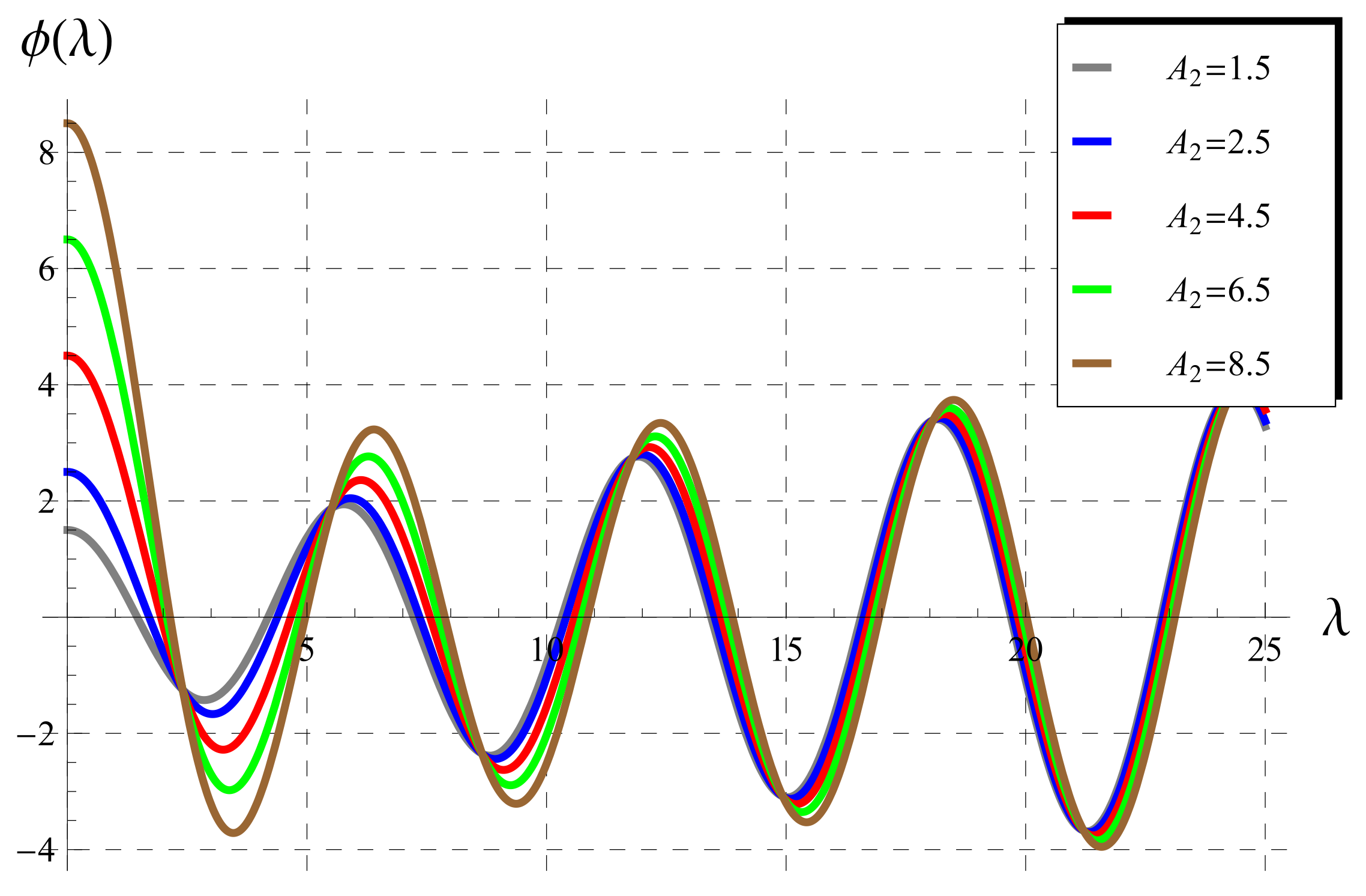
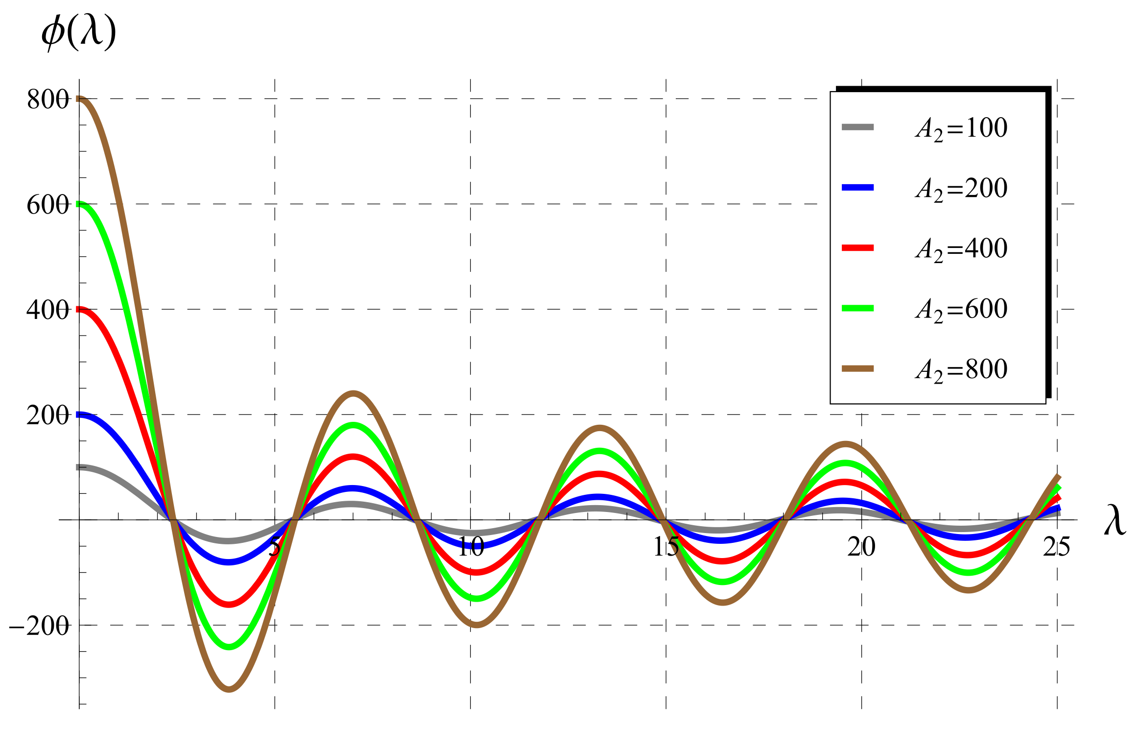
Behavior of ϕ ( λ ) is depicted in Figure 1, Figure 2, Figure 3, Figure 4 and Figure 5 at various values of A 2 . It is verified in all figures that there is an infinite number of roots. However, the roots are nearly identical for small A 2 [ 0 , 1 ) (Figure 1), except the first root. The thin curve (black, dashed) represents the function ϕ ( λ ) = λ J 1 ( λ ) ( A 2 = 0 ). For A 2 [ 1 , 10 ) , it can be conducted from Figure 2 that the roots, after the first seven ones, have approximately the same values. From Figure 3, it can be seen that the first two roots are nearly identical for A 2 [ 10 , 50 ) , the rest of roots are different. For relatively higher values of A 2 [ 50 , 100 ) (Figure 4) and A 2 [ 100 , 1000 ) (Figure 5), the roots are nearly identical as shown from Figure 4 and Figure 5. Although an infinite number of roots exist for the equation ϕ ( λ ) = 0 , Biswas et al. [4] considered certain approximate analytic formulas, using fitting data, for only the first three roots λ 1 , λ 2 and λ 3 when deriving their results. Moreover, Yeh et al. [5] obtained an approximate formula for the first root and then they established their results. Furthermore, Mahrous [6] derived the first two roots and gave approximate analytic forms and then compared his results with Biswas et al. [4] and Yeh et al. [5]. In Table 1, the numeric values of the first three roots λ 1 , λ 2 and λ 3 of Equation (24) are listed.

5.2. Experimental Values of A 2 (Wall Decay Rate)

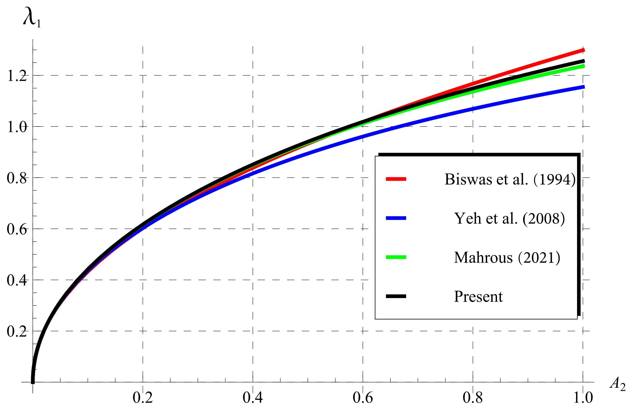
Yeh et al. [5] mentioned that the values of A 2 are smaller than 0.1 according to the experimental studies for chlorine decay. Therefore, the comparison between the present results and those in the relevant literature are performed taking into account such experimental considerations, i.e., A 2 < 0.1 . For this reason, Yeh et al. [5] considered only the first root λ 1 of Equation (24) and they obtained approximate expression λ 1 = 4 A 2 2 + A 2 . Such λ 1 was obtained by Biswas et al. [4] as λ 1 = 1.29861 ( A 2 ) 0.477433 , while Mahrous [6] derived λ 1 = 2 2 + A 2 4 + A 2 2 . The comparison between the present numerical values for λ 1 , against A 2 , and the above approaches is displayed in Figure 6. It is concluded from this figure that the values of Ref. [6] are the best when compared with the true numerical ones using Wolfram MATHEMATICA 12.

5.3. Comparisons as α 1 (Classical Chlorine Decay)

In the case of α 1 , Biswas et al. [4] deduced the following approximation:
u av = e A 1 x 1 + ϵ , ϵ = 2.4416 A 0 A 2 0.1559 A 0 A 2 2 , 0.01 A 2 10 ,
as a consequence of the regression technique. In addition, Yeh et al. [5] showed that the u av can be approximated as
u av = 1 + 2 A 2 4 + 2 A 2 + A 2 2 e A 1 + 4 A 0 A 2 2 + A 2 x , 0 A 2 < 0.1 .
In addition, accurate approximate solution was obtained by Mahrous [6] in the form
u av = 4 A 2 2 n = 1 2 e ( A 1 + A 0 λ n 2 ) x λ n 2 A 2 2 + λ n 2 , λ 1 , 2 = 2 2 + A 2 4 + A 2 2 , 0 A 2 1 .
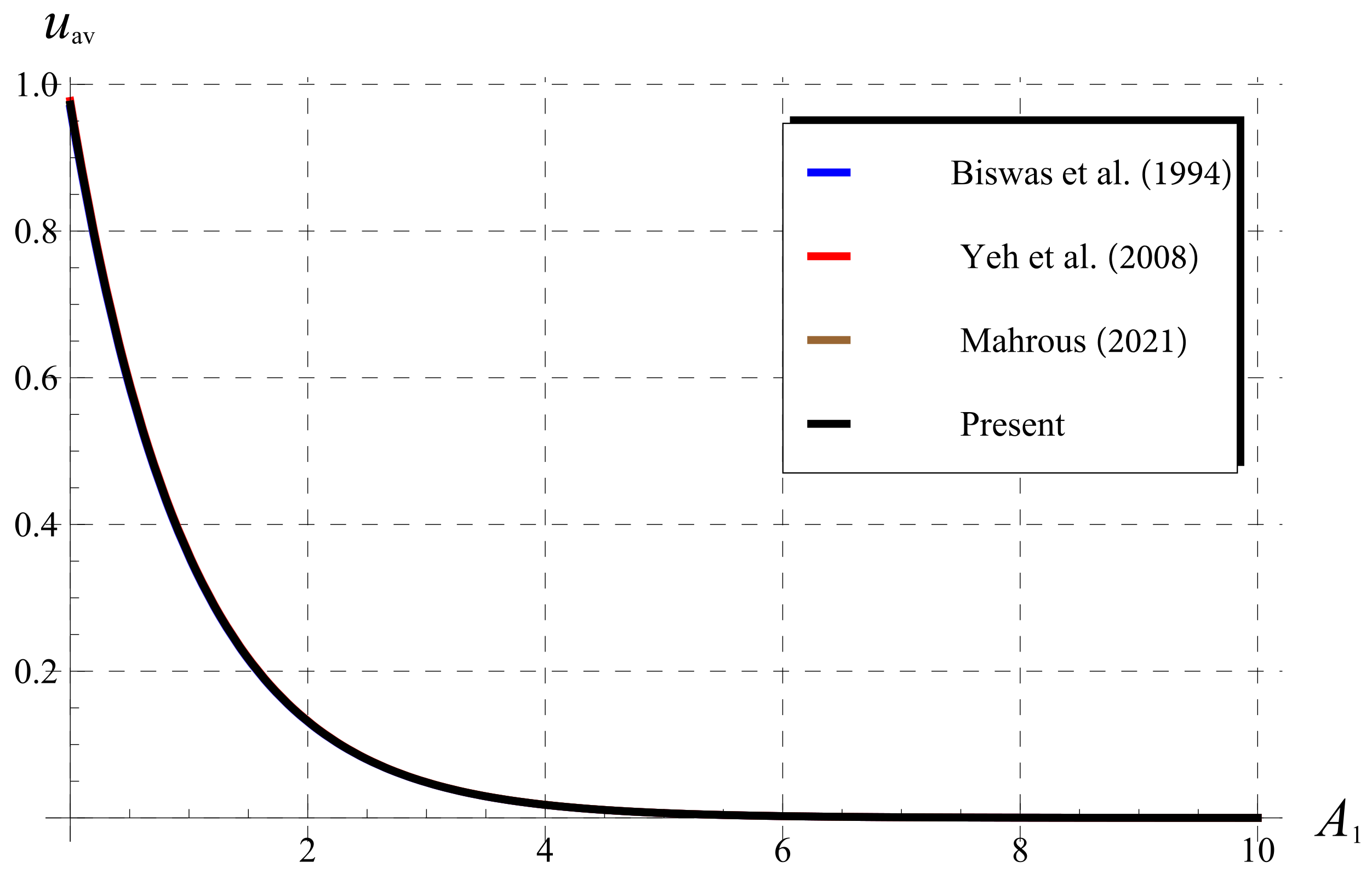
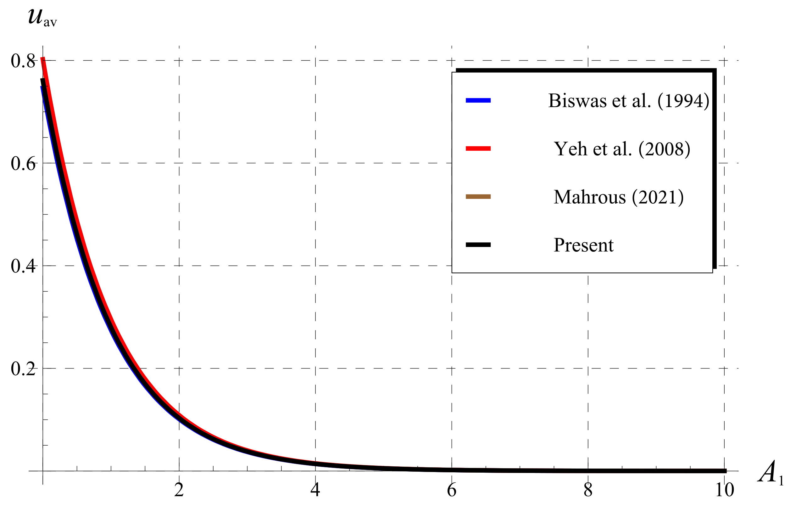
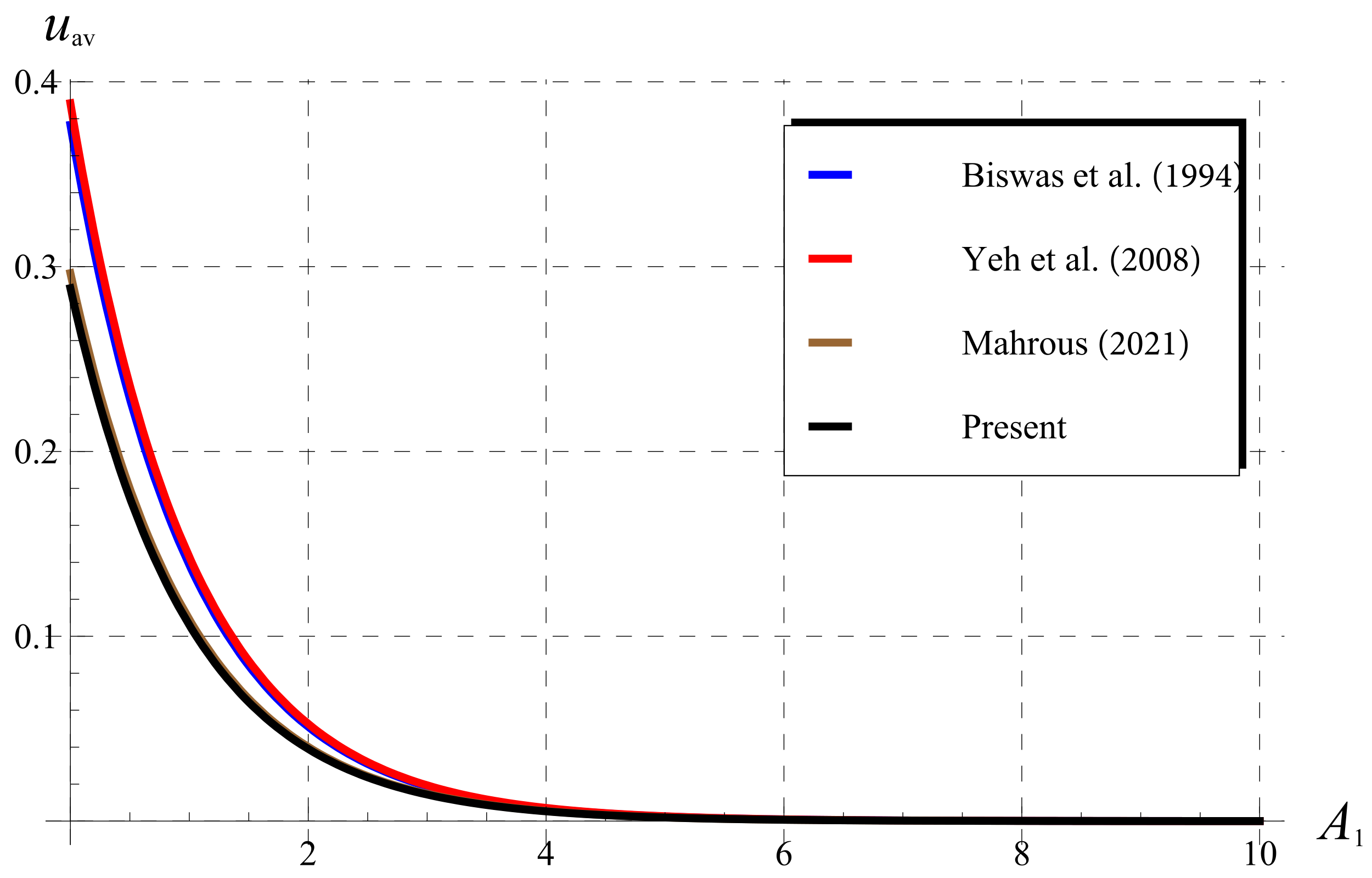
In Figure 7, Figure 8 and Figure 9, the present u av (given in Equation (38)) is displayed versus A 1 (water decay rate), at the outlet x = 1 of a pipe, and compared with the above different approximations. The first three roots listed in Table 1 are used to conduct our results. For a fixed radial diffusivity value A 0 = 1.4 , the comparisons are performed for A 2 = 0.01 (Figure 7), A 2 = 0.1 (Figure 8), and A 2 = 0.5 (Figure 9). It can be seen from Figure 7 and Figure 8 that our results coincide with the published ones by Biswas et al. [4], Yeh et al. [5], and Mahrous [6]. However, the current results agree only with Mahrous [6] in Figure 9 when A 2 is slightly increased ( A 2 = 0.5 ). This is because the value A 2 = 0.5 lies outside the range of validity addressed by Yeh et al. [5] ( 0 A 2 < 0.1 ). Although A 2 = 0.5 lies inside the range of validity conducted by Biswas et al. [4] ( 0.01 A 2 10 ), their estimated expression for the u av deviate from our results and those of Mahrous [6]. Probably, the fitting data used by Biswas et al. [4] needs revisions in this case.

5.4. Comparisons for α ( 0 , 1 ] (Fractional Chlorine Decay)

In this section, the behavior of the present cup-mixing average concentration u av in the FC, given in Equation (37) and the the corresponding one in Ref. [7] are declared. For fractional chlorine decay, i.e., α ( 0 , 1 ] , Mahrous [7] obtained the following exact solution for the u av :
u av = E α A 1 x α 1 α e ( A 1 ) 1 / α x + 4 n = 1 A 2 2 λ n 2 A 2 2 + λ n 2 e A 1 A 0 λ n 2 1 / α x .
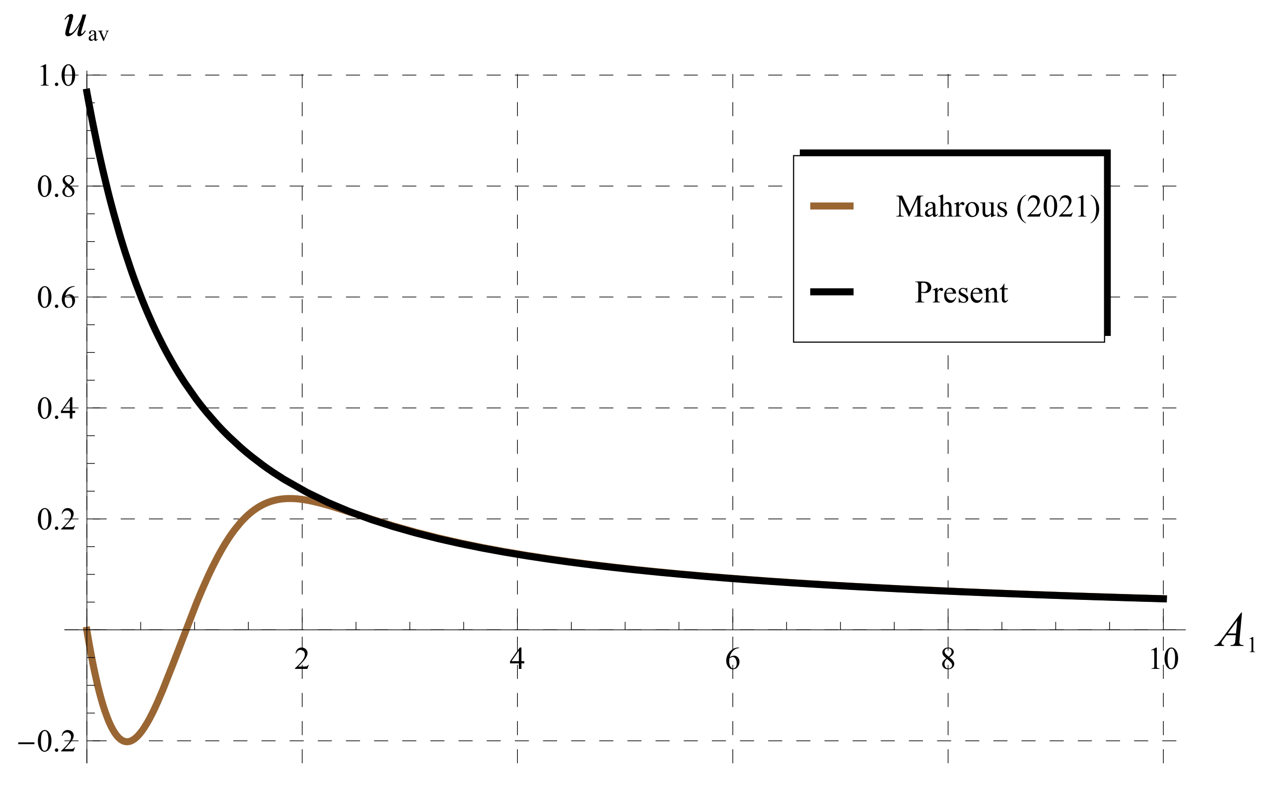
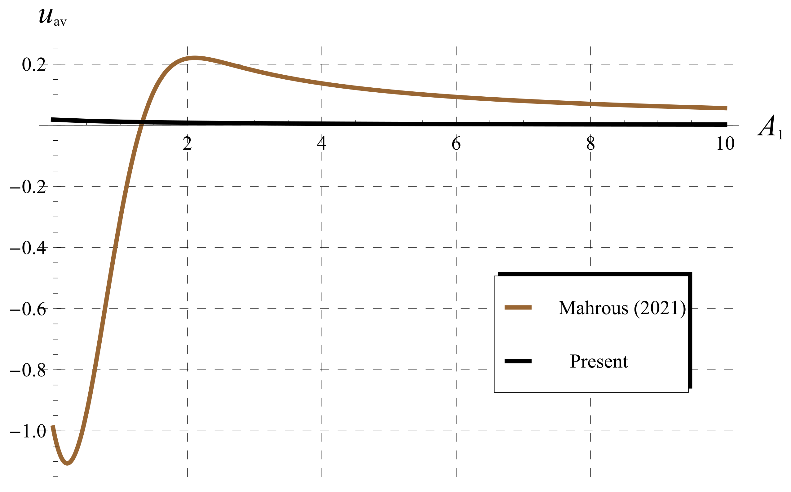
For fixed α = 1 / 2 and A 0 = 1.4 , the comparisons between the two approaches in the FC are displayed through Figure 10, Figure 11 and Figure 12 for the u av at A 2 = 0.01 (Figure 10), A 2 = 0.1 (Figure 11), and A 2 = 0.5 (Figure 12). Here, it may be important to mention to that both of our approach and Ref. [7] use the same numeric values of the three roots in Table 1. However, a big difference in the behavior of u av is detected. In all figures, the present u av decreases with increasing A 2 in the whole domain, while the behavior of corresponding one in Ref. [7] is completely different. In addition, the u av in Ref. [7] becomes negative in sub-domains of A 1 , namely at the beginning. Moreover, the effect of α on the variation of u av can be interpreted. Our curves in Figure 10, Figure 11 and Figure 12 (black) at α = 1 / 2 are always lower than those of Figure 7, Figure 8 and Figure 9 (black) as α 1 . So, the u av in the FC is of less amount than in classical calculus. As a final note on the comparisons made above, the present analysis agrees with the physical requirements of the problem, where the present u av is always positive, i.e, unlike the negativity in Ref. [7]. In conclusion, the current analysis gives a clear picture and accurate solution of the chlorine decay in the FC.

6. Conclusions

The transport model of the chlorine concentration decay in the FC was investigated. The SOV method combined with the LT were applied to solve the current model. The dimensionless cup-mixing average concentration was obtained in closed form in terms of the Mittag-Leffler function. It was declared that the results reduce to the standard ones in the literature as the fractional order α tends to one. The obtained results were compared with several studies in the literature, and the difference in results is explained and interpreted in detail. In view of these comparisons, it can be concluded that the present analysis was effective to giving a clear picture and accurate solution for the chlorine transport model in the FC when compared with the previous solution in [7] for the same model.

Author Contributions

Conceptualization, A.F.A., A.E.; methodology, A.F.A., A.E. and H.K.A.-J.; software, E.A.A.; validation, C.C., A.F.A. and A.E.; resources, Y.M.M.; data curation, Y.M.M.; writing—original draft preparation, A.F.A., E.A.A. and A.E.; writing—review and editing, H.K.A.-J.; visualization, A.F.A., C.C., and Y.M.M.; supervision, A.F.A. and C.C.; project administration, A.F.A.; funding acquisition, A.F.A. All authors have read and agreed to the published version of the manuscript.

Funding

The authors extend their appreciation to the Deanship of Scientific Research at University of Tabuk for funding this work through Research Group No. S-0147-1441.

Institutional Review Board Statement

Not applicable.

Informed Consent Statement

Not applicable.

Data Availability Statement

Not applicable.

Conflicts of Interest

The authors declare no conflict of interest.

References

  1. Clark, R.M.; Read, E.J.; Hoff, J.C. Analysis of Inactivation of Giardia Lamblia by Chlorine. J. Environ. Eng. 1989, 115, 80–90. [Google Scholar] [CrossRef]
  2. LeChevallier, M.W.; Cawthon, C.D.; Lee, R.G. Inactivation of biofilm bacteria. Appl. Environ. Microbiol. 1988, 54, 2492–2499. [Google Scholar] [CrossRef] [PubMed] [Green Version]
  3. Arnold, B.F.; Colford, J.M. Treating Water with Chlorine at Point-of-Use to Improve Water Quality and Reduce Child Diarrhea in Developing Countries: A Systematic Review and Meta-Analysis. Am. J. Trop. Med. Hyg. 2007, 76, 354–364. [Google Scholar] [CrossRef] [PubMed] [Green Version]
  4. Biswas, P.; Lu, C.; Clark, R.M. A model for chlorine concentration decay in pipes. Water Res. 1993, 27, 1715–1724. [Google Scholar] [CrossRef]
  5. Yeh, H.-D.; Wen, S.-B.; Chang, Y.-C.; Lu, C.-S. A new approximate solution for chlorine concentration decay in pipes. Water Res. 2008, 42, 2787–2795. [Google Scholar] [CrossRef]
  6. Mahrous, Y.M. Accurate approximation for the chlorine transport in pipe. Adv. Differ. Equ. Control Process. 2021, 25, 115–126. [Google Scholar] [CrossRef]
  7. Mahrous, Y.M. A possible generalized model of the chlorine concentration decay in pipes: Exact solution. Int. Anal. Appl. 2021, 19, 604–618. [Google Scholar] [CrossRef]
  8. Monteiro, L.; Viegas, R.; Covas, D.; Menaia, J. Assessment of Current Models Ability to Describe Chlorine Decay and Appraisal of Water Spectroscopic Data as Model Inputs. J. Environ. Eng. 2017, 143, 04016071. [Google Scholar] [CrossRef]
  9. Zhao, Y.; Yang, Y.J.; Shao, Y.; Neal, J.; Zhang, T. The dependence of chlorine decay and DBP formation kinetics on pipe flow properties in drinking water distribution. Water Res. 2018, 141, 32–45. [Google Scholar] [CrossRef]
  10. Fisher, I.; Kastl, G.; Sathasivan, A. New Model of Chlorine-Wall Reaction for Simulating Chlorine Concentration in Drinking Water Distribution Systems. Water Res. 2017, 125 (Suppl. C), 427–437. [Google Scholar] [CrossRef]
  11. Ozdemir, O.; Buyruk, T. Effect of travel time and temperature on chlorine bulk decay in water supply pipes. J. Environ. Eng. 2018, 144, 04018002. [Google Scholar] [CrossRef]
  12. Minaee, R.P.; Afsharnia, M.; Moghaddam, A.; Ebrahimi, A.A.; Askarishahi, M.; Mokhtari, M. Calibration of water quality model for distribution networks using genetic algorithm, particle swarm optimization, and hybrid methods. MethodsX 2019, 6, 540–548. [Google Scholar] [CrossRef] [PubMed]
  13. Minaee, R.P.; Afsharnia, M.; Moghaddam, A.; Ebrahimi, A.A.; Askarishahi, M.; Mokhtari, M. Wall decay coefficient estimation in a real-life drinking water distribution network. Water Resour. Manag. 2019, 33, 1557–1569. [Google Scholar] [CrossRef]
  14. Monteiro, L.; Carneiro, J.; Covas, D.I.C. Modelling chlorine wall decay in a full-scale water supply system. Urban Water J. 2020, 17, 754–762. [Google Scholar] [CrossRef]
  15. Moghaddam, A.; Mokhtari, M.; Afsharnia, M.; Minaee, R.P. Simultaneous Hydraulic and Quality Model Calibration of a Real-World Water Distribution Network. J. Water Resour. Plan. Manag. 2020, 146, 06020007. [Google Scholar] [CrossRef]
  16. Jakubowski, J.; Wisniewolski, M. On matching diffusions, Laplace transforms and partial differential equations. Stoch. Proc. Appl. 2015, 125, 3663–3690. [Google Scholar] [CrossRef] [Green Version]
  17. Ebaid, A.; Sharif, M.A. Application of Laplace transform for the exact effect of a magnetic field on heat transfer of carbon-nanotubes suspended nanofluids. Z. Naturforsch. A 2015, 70, 471–475. [Google Scholar] [CrossRef]
  18. Ebaid, A.; Wazwaz, A.M.; Alali, E.; Masaedeh, B. Hypergeometric series solution to a class of second-order boundary value problems via Laplace transform with applications to nanofluids. Commun. Theor. Phys. 2017, 67, 231. [Google Scholar] [CrossRef]
  19. Ebaid, A.; Alali, E.; Saleh, H. The exact solution of a class of boundary value problems with polynomial coefficients and its applications on nanofluids. J. Assoc. Arab Univ. Basi Appl. Sci. 2017, 24, 156–159. [Google Scholar] [CrossRef]
  20. Khaled, S.M. The exact effects of radiation and joule heating on magnetohydrodynamic Marangoni convection over a flat surface. Therm. Sci. 2018, 22, 63–72. [Google Scholar] [CrossRef]
  21. Bakodah, H.O.; Ebaid, A. Exact solution of Ambartsumian delay differential equation and comparison with Daftardar-Gejji and Jafari approximate method. Mathematics 2018, 6, 331. [Google Scholar] [CrossRef] [Green Version]
  22. Ebaid, A.; Cattani, C.; Juhani1, A.S.A.; El-Zahar, E.R. A novel exact solution for the fractional Ambartsumian equation. Adv. Differ. Equ. 2021, 2021, 88. [Google Scholar] [CrossRef]
  23. Handibag, S.; Karande, B.D. Laplace substitution method for solving partial differential equations involving mixed partial derivatives. Int. J. Comput. Eng. Res. 2012, 2, 1049–1052. [Google Scholar]
  24. Handibag, S.S.; Karande, B.D. Laplace substitution method for nth order linear and non-Linear PDE’s involving mixed partial derivatives. Int. Res. J. Eng. Technol. 2015, 2, 378–388. [Google Scholar]
  25. Pavani, P.V.; Priya, U.L.; Reddy, B.A. Solving differential equations by using Laplace transforms. Int. J. Res. Anal. Rev. 2018, 5, 1796–1799. [Google Scholar]
  26. Dhunde, R.R.; Waghmare, G.L. Double Laplace iterative method for solving nonlinear partial differential equations. New Trends Math. Sci. 2019, 7, 138–149. [Google Scholar] [CrossRef]
  27. Mousa, A.; Elzaki, T.M. Solution of volterra integro-differential equations by triple Laplace transform, Irish Interdiscip. J. Sci. Res. 2019, 3, 67–72. [Google Scholar]
  28. Zhang, H.; Nadeem, M.; Rauf, A.; Hui, Z.G. A novel approach for the analytical solution of nonlinear time-fractional differential equations. Int. J. Numer. Meth. Heat Fluid Flow 2021, 31, 1069–1084. [Google Scholar] [CrossRef]
  29. Ebaid, A.; Al-Jeaid, H.K. The Mittag–Leffler Functions for a Class of First-Order Fractional Initial Value Problems: Dual Solution via Riemann-Liouville Fractional Derivative. Fractal Fract. 2022, 6, 85. [Google Scholar] [CrossRef]
  30. Srivastava, H.M.; Kumar, A.; Das, S.; Mehrez, K. Geometric Properties of a Certain Class of Mittag-Leffler-Type Functions. Fractal Fract. 2022, 6, 54. [Google Scholar] [CrossRef]
  31. Alharb, W.; Hristova, S. New Series Solution of the Caputo Fractional Ambartsumian Delay Differential Equationation by Mittag-Leffler Functions. Mathematics 2021, 9, 157. [Google Scholar] [CrossRef]
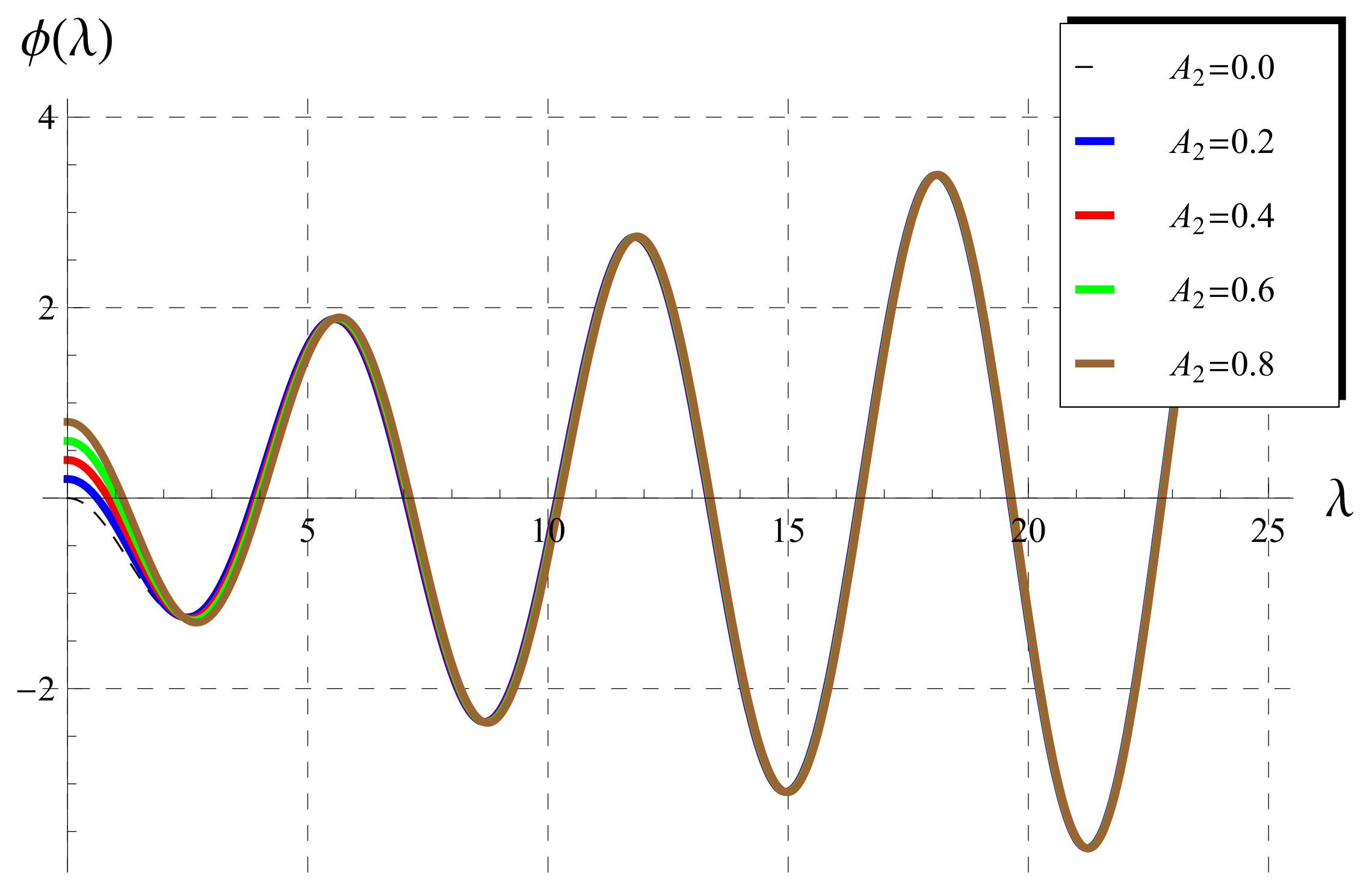
Figure 1. Behavior of ϕ ( λ ) vs. λ in the range 0 A 2 < 1 . The thin curve (black, dashed) represents the function ϕ ( λ ) = λ J 1 ( λ ) ( A 2 = 0 ).
Fractalfract 06 00125 g001
Figure 2. Behavior of ϕ ( λ ) vs. λ in the range 1 A 2 < 10 .
Fractalfract 06 00125 g002
Figure 3. Behavior of ϕ ( λ ) vs. λ in the range 10 A 2 < 50 .
Fractalfract 06 00125 g003
Figure 4. Behavior of ϕ ( λ ) vs. λ in the range 50 A 2 < 100 .
Fractalfract 06 00125 g004
Figure 5. Behavior of ϕ ( λ ) vs. λ in the range 100 A 2 < 1000 .
Fractalfract 06 00125 g005
Figure 6. Comparisons between the present numerical and the published approximate values of the first root λ 1 vs. A 2 [4,5,6].
Fractalfract 06 00125 g006
Figure 7. Comparisons between the present cup-mixing average concentration u av and the corresponding ones in literature as α 1 when A 0 = 1.4 and A 2 = 0.01 [4,5,6].
Fractalfract 06 00125 g007
Figure 8. Comparisons between the present cup-mixing average concentration u av and the corresponding ones in literature as α 1 when A 0 = 1.4 and A 2 = 0.1 [4,5,6].
Fractalfract 06 00125 g008
Figure 9. Comparisons between the present cup-mixing average concentration u av and the corresponding ones in literature as α 1 when A 0 = 1.4 and A 2 = 0.5 [4,5,6].
Fractalfract 06 00125 g009
Figure 10. Comparisons between the present cup-mixing average concentration u av and the corresponding ones in Mahrous [7] at α = 1 2 (fractional chlorine decay), A 0 = 1.4 , and A 2 = 0.01 .
Fractalfract 06 00125 g010
Figure 11. Comparisons between the present cup-mixing average concentration u av and the corresponding ones in Mahrous [7] at α = 1 2 (fractional chlorine decay), A 0 = 1.4 , and A 2 = 0.1 .
Fractalfract 06 00125 g011
Figure 12. Comparisons between the present cup-mixing average concentration u av and the corresponding ones in Mahrous [7] at α = 1 2 (fractional chlorine decay), A 0 = 1.4 , and A 2 = 0.5 .
Fractalfract 06 00125 g012
Table 1. The numerical values of λ 1 , λ 2 , and λ 3 of Equation (24) at different values of A 2 .
A 2 λ 1 λ 2 λ 3
0.010.141253.834317.01701
0.10.441683.857717.02983
0.20.616983.883517.04403
0.50.940773.959377.08638
11.255784.079487.15580
21.599454.290967.28839
51.989814.713147.61771
102.179505.033217.95688
502.357245.411208.48399
1002.380905.465218.56783
Publisher’s Note: MDPI stays neutral with regard to jurisdictional claims in published maps and institutional affiliations.