Article

Randomly Generating the 3D Mesostructure of Soil Rock Mixtures Based on the Full In Situ Digital Image Processed Information

1
School of Mine Safety, North China Institute of Science and Technology, Xueyuan Road, Sanhe, Langfang 065201, China
2
Center for Research and Education in Advanced Transportation Engineering Systems (CREATEs), Department of Civil and Environmental Engineering, Rowan University, 201 Mullica Hill Road, Glassboro, NJ 08028, USA
3
School of Safety Enigeering, North China Institute of Science and Technology, Xueyuan Road, Sanhe, Langfang 065201, China
4
Hulun Buir Dongming Mining Industry, Chenbaerhu Banner, Hulunbuir 021500, China
*
Author to whom correspondence should be addressed.
Fractal Fract. 2022, 6(10), 570; https://doi.org/10.3390/fractalfract6100570
Submission received: 26 August 2022 / Revised: 1 October 2022 / Accepted: 5 October 2022 / Published: 7 October 2022
(This article belongs to the Section Engineering)

Abstract

:
Understanding the occurrence and evolution of geological disasters, such as landslides and debris flows, is facilitated by research on the performance of soil rock mixes (SRM). Recently, more and more researchers have been interested in studying the mesostructure reconstruction process of SRM. The present mesostructure generation approaches, however, have several weaknesses. One of the weaknesses is that they do not consider the impact of particle shape and therefore cannot ensure similarity to the in situ SRMs. In this study, a new mesostructure generation method that randomly generates SRMs based on the full in situ digital image processing (DIP) information is proposed. The generation procedure of the proposed algorithm considers the geometry characteristics of in situ SRMs, including the size distribution, particle shape, and 2D fractal dimension of the cross-section. A parametric study was performed to examine how the rock content and particle shape affected the fractal dimension of the generated SRMs. The results indicate that as the rock content increases in intensity, the fractal dimension also increases. Only when the angular particle content is less than 75% does it affect the fractal dimension. The fractal dimension of the generated mesostructures increases with the increase in the angular particle proportion under the same rock content.

1. Introduction

Soil-rock mixture (SRM) is an inhomogeneous mixture that is composed of hard rocks and relatively soft soils and pores [1]. SRM is a widely distributed substance in nature that is frequently encountered in geotechnical engineering projects such as the slope stability of open-pit mines and the stability of foundations [2,3]. Furthermore, the study of the mechanical behavior of SRM aids in the understanding of the occurrence and evolution of geological disasters including landslides and debris flows [4,5].
Traditional methods of investigating the mechanical behavior of SRM are based on the homogeneous assumption and macroscopic analysis. These studies consider SRM as a homogeneous material and focus on the overall mechanical properties of SRM. For example, Medley et al. [6] performed laboratory tests with scale models to investigate the strength and deformation characterization of SRMs. Zhang et al. [7] investigated the influence of grain size distribution on the mechanical behavior of SRMs by performing triaxial tests on three types of SRMs with varied grain size distributions. Dong et al. [8] performed large-scale triaxial tests to explore the influence of structural parameters, the parent rock type, and the weathering degree on the general mechanical behaviors of SRMs. However, SRMs are very diverse materials with considerable differences in terms of mechanical strength between hard rock grains and soft soils. Extensive experimental testing has indicated that the mechanical properties of SRMs are influenced by the mesostructure features such as the rock grain percentage, angle, and size [9,10,11]. As a result, mesostructure research and its impact on mechanical characteristics is becoming increasingly significant in the study of SRMs.
There has been an increasing number of studies on the mesostructure of SRMs in recent years [12,13]. These studies can be classified into two groups. The first group uses a digital image processing (DIP) method based on images from an X-ray CT or a high-resolution camera to reconstruct the mesostructure of SRMs. For example, Xu et al. [1] adopted a DIP method to reconstruct the mesostructure of SRMs statistically and simulated the mechanical response using finite element methods. Meng et al. [14] introduced a DIP-based discrete element method (DEM) to reconstruct and analyze the mesostructure of SRM. However, one major drawback of this approach is that the digital image used in this method can only capture the 2D information of the mesostructure of SRMs. The second group of studies investigating the mesostructure of SRMs involves the creation of numerical models based on randomly generated mesostructures with Monte Carlo simulation. In recent years, several robust algorithms for randomly generating the 2D mesostructure of SRMs were proposed [15,16]. Similar to the DIP-based reconstruction method, these 2D algorithms overlooked the 3D characteristics of the mesostructure. As a result, new attempts have been made to randomly produce the 3D mesostructure of SRMs with Monte Carlo simulation.
Several attempts have been made to randomly generate the 3D mesostructures of SRMs. These generated mesostructures can be used for further numerical simulations with techniques such as the finite element method (FEM) or the discrete element method (DEM). For example, Xu et al. [17] proposed an algorithm for randomly generating irregular rock by growing new tetrahedrons on a hexahedron base. Xu’s approach is effective at producing angular grains, especially those that are flat or elongated. Sheng et al. [18] applied a free-fall acceleration method to accelerate the generation process of the 3D mesostructure with convex particles. Meng et al. [19] developed a novel method that can generate 3D mesostructure with both concave and convex particles. Sheng and Meng’s idea of generating grain particles was to randomly pick vertices within a spherical particle. This method works well for generating rounded particles but not for angular particles.
In conclusion, the current technique for creating 3D mesostructures can only produce one sort of grain (i.e., either angular or rounded). However, as a nature material, SRMs contain two types of particles. Furthermore, existing algorithms only evaluate the size distributions of the rock grains while constructing the mesostructures, ignoring other SRM factors such as the shape (angular/rounded) or fractal dimension.
In this paper, we integrated current algorithms for generating 3D mesostructures of SRMs and proposed a new method that randomly generates SRMs based on the full in situ DIP information. The novel proposed method guarantees the the accuracy of the reconstruction process by taking into account all in situ SRM factors, including size distribution, angular/rounded particle content, and 2D fractal dimension. In addition, the influence of the rock content and the shape of the rock grains on the fractal dimension of the cross-section of SRMs was analyzed in this paper.

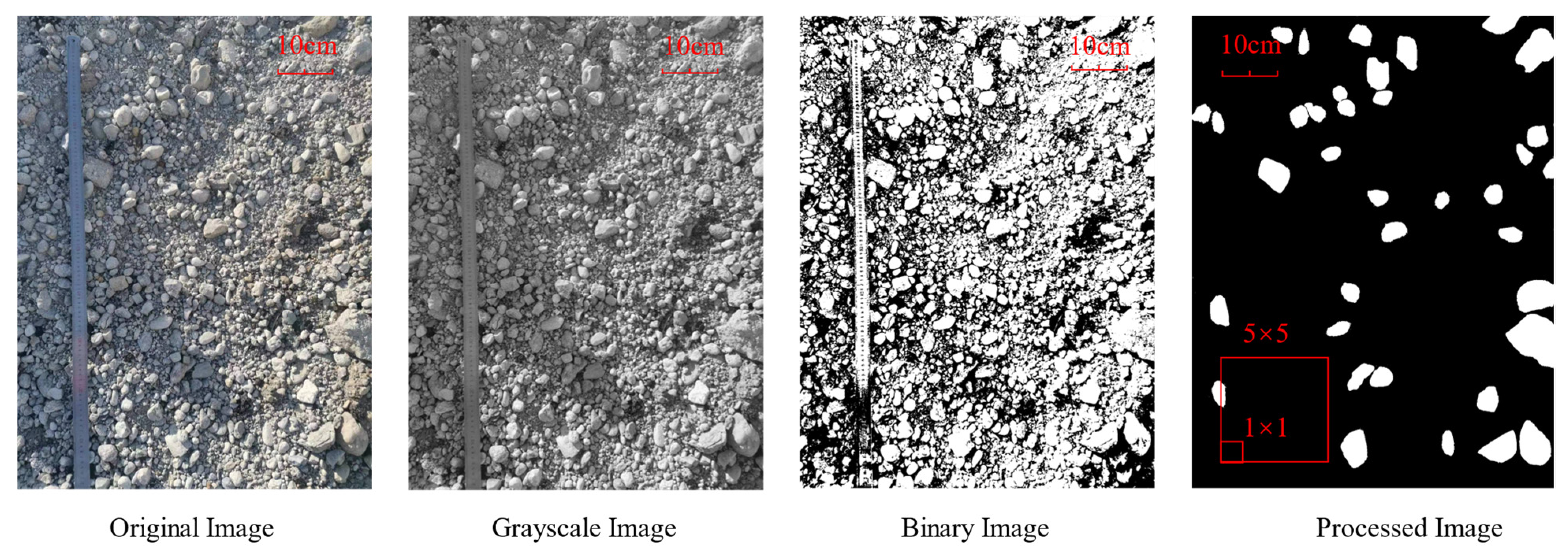
2. Full In Situ SRM Mesostructure Characterization

Identifying the geometry characterization of the mesostructure of SRMs is the first step that guarantees that the reconstructed model has similar structures to the in situ SRMs. In previous related studies, only the grain size distribution of SRMs was used as an input parameter during the mesostructure generation process. However, an analysis of particle shapes indicated that the shape of rock grains has a significant influence on the overall properties of SRMs [20]. To address this problem, an efficient method that characterizes the full in situ geometry properties of SRMs was proposed in this study. These geometry properties include size distribution, particle shape, and the fractal dimension of in situ SRMs. The size distribution of SRMs was tested based on the sieving test, and the particle shape was tested by the flat and elongated test. The fractal dimension of in situ SRM was calculated using the DIP method based on the high-resolution digital image.
An example of the digital image processing steps is shown in Figure 1. The digital image of SRMs was taken from the Hulun Buir Dongming Open-pit Mining Industry, China. The first step of digital image processing is transferring the original image into a grayscale figure. By selecting the appropriate threshold, the grayscale image was then transferred into a binary image. Based on the definition of Medley et al. [6], the threshold size that distinguishes soil and rock grains is 0.05Lc, where Lc is the characteristic engineering dimension. In this study, the characteristic engineering dimension is 1 m; therefore, all particles with a length larger than 5 cm were recognized as rock grains. All particles with a size smaller than 5 cm were painted black, as shown in Figure 1.
The fractal dimension of the processed image was calculated based on the box counting method. The box counting method divides the image into several squares with the side length l. The number of squares that cover the rock areas N varies with the side length l. The number of squares N decreases with the increase in the side length l. The fractal dimension of the 2D image was calculated by fitting the following equation:
log ( N ) = F log ( 1 / l )
where F is the fractal dimension.

3. 3D Mesostructure-Generating Algorithm

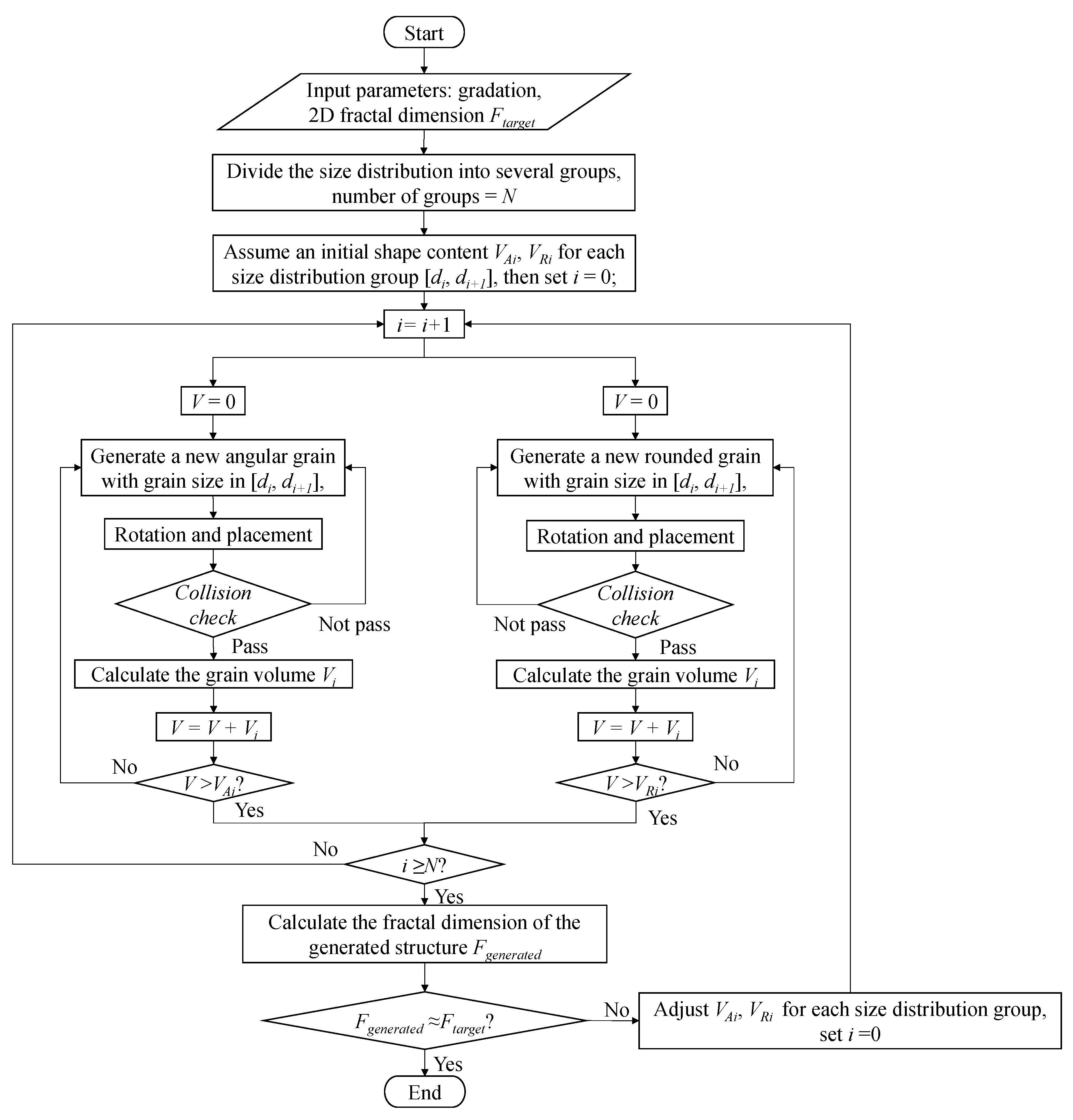
3.1. Mesostructure Generation Procedure

The proposed mesostructure generation method takes the full in situ SRM parameters including the size distribution, the shape of the grains, and the 2D fractal dimension of the cross-section into consideration during the generation process. The size distribution of SRMs is usually obtained from the sieving test. From the gradation curve of the sieving test, the cumulative percentage in a certain size range could be calculated. The volume percentage of different shapes of grains was used as a fitting parameter that adjusts the 2D fractal dimension of the cross-section of the generated SRM structure. The specific generation procedure is shown in the flowchart in Figure 2.
As shown in Figure 2, the first step of mesostructure generation is inputting the in situ parameters of SRMs. The parameters include the gradation curve and 2D fractal dimension based on the DIP method. The size of grains was then divided into N groups. For each group, an initial volume content for two shapes (angular and rounded) was assumed. After that, two types of grains were generated until the volume content reached the target size distribution. When all N groups of grains were generated, the fractal dimension of the cross-section of the generated structures was calculated and compared with the in situ 2D fractal dimension. If the generated mesostructure has a similar fractal dimension to the in situ SRMs, the generation process is finished. Otherwise, the content of the angular and rounded grains is adjusted until the fractal dimension of the generated structure fits with the in situ samples.
The specific algorithm for generating angular and rounded grains, rotation and placement, collision detection, and fractal dimension calculation is presented in the following sections.

3.2. Generation of the Single Grain

The shape of the grains in the SRM mesostructure was taken into account in the generation process. Two types of grain shapes were considered in this study: rounded and angular (flat or elongated). These two shapes of grains were generated with two different methods.

3.2.1. Generation of Angular Grains

The idea of generating angular grains involves adding new tetrahedrons on a base tetrahedron. The vertices of each tetrahedron were constrained within a pre-defined sphere to guarantee the maximum size of the generated grain. Figure 3 illustrates the angular grains generation process. The steps of generating angular grains are as follows:
  • Based on the given grain size, generate a pre-defined sphere with a diameter equal to the grain size. This sphere is not part of the created grain and is used to ensure that all generated vertices are within the defined range.
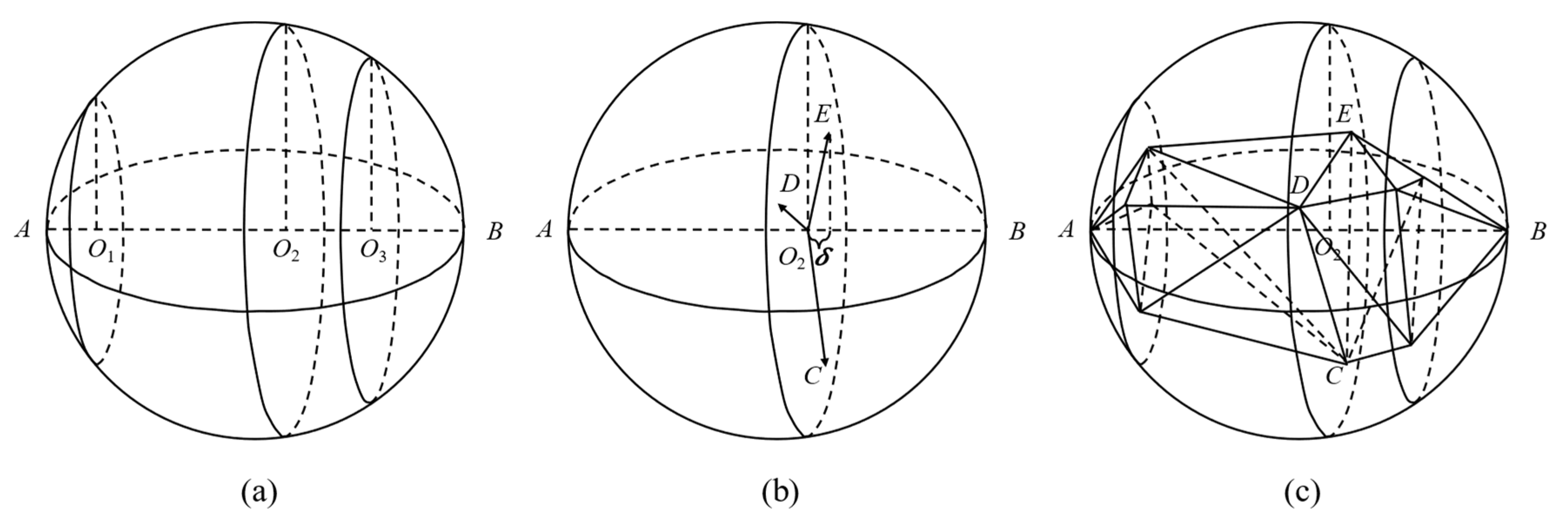
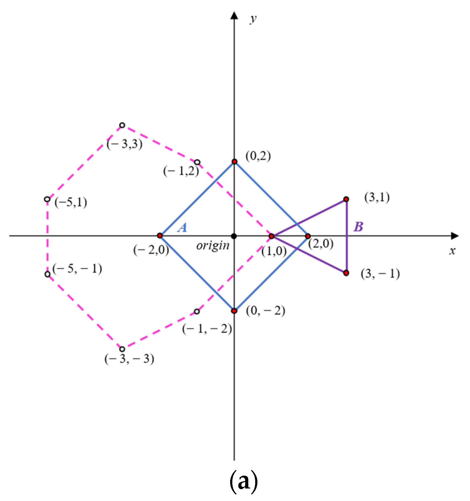
  • Generate the base tetrahedron. An example of the base tetrahedron is shown in Figure 3a. For the base tetrahedron, two vertices, A and B, are fixed as two vertices on the diameter of the pre-defined sphere, and the other two vertices, C and D, are randomly picked within the sphere. In this way, the size of the generated grain is the distance between points A and B (i.e., the given grain size).
  • Generate a new vertex on the triangle with the largest surface area. An example of this step is shown in Figure 3b. Taking the triangle ADC as an example, the surface area was calculated by the equation as follows:
    S A D C = | A D × A C | 2
    Once the triangle with the largest surface area was determined, the new vertex E was generated by a vector that passed through the center of the pre-defined sphere (O), along with the normal vector of the triangle. The length of OE was determined by multiplying the radius of the sphere by a random number ranging from 0 to 1.
  • Generate a new tetrahedron based on the newly generated vertex E. The new tetrahedron was formed by the three vertices of the triangle with the largest surface area (ADC in Figure 3b) and the newly generated vertex E.
  • Repeat steps 3 to 4 until the number of vertices or the maximum surface area reaches the requirement.

3.2.2. Generation of Rounded Grains

The algorithm of generating rounded grains is based on the method of randomly picking vertices on the intersections of the pre-defined sphere. This approach works well for producing rounded grains. Figure 4 depicts the rounded grain generation process. The generation steps are as follows:
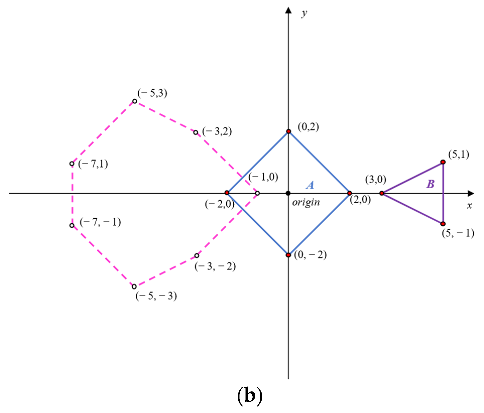
  • Like the generation process of angular grains, the first step of generating rounded grains is generating a pre-defined sphere based on the given grain size. The diameter of the sphere is equal to the grain size. Two vertices on the diameter of the pre-defined sphere, A and B, are selected at the initial vertices of the grain.
  • Randomly pick several points on the diameter AB and determine the intersections that are perpendicular to AB, as shown in Figure 4a.
  • For each intersection, randomly select several points within the intersected circle; then, add a random offset d on the AB direction, as shown in Figure 4b.
  • Connect all generated vertices and form the grains, as shown in Figure 4c.

3.3. Grain Rotation and Placement

The proposed SRM mesostructure generation algorithm adopted the Monte-Carlo method to determine the coordinates and directions of the generated grains. After generating a single grain, the coordinates of the vertices were transformed by the following equation:
( x 1 , y 1 , z 1 ) = ( x 0 , y 0 , z 0 ) [ cos ( α ) sin ( α ) 0 sin ( α ) cos ( α ) 0 0 0 1 ] [ cos ( β ) 0 sin ( β ) 0 1 0 sin ( β ) 0 cos ( β ) ] [ 1 0 0 0 cos ( γ ) sin ( γ ) 0 sin ( γ ) cos ( γ ) ] + ( r 1 L , r 2 W , r 3 H )
where (x0, y0, z0) are the initial coordinates of the vertex; (x1, y1, z1) are the transformed coordinates; α, β, and γ are random angles ranging from 0 to 360 degrees; r1, r2, and r3 are random constants ranging from 0 to 1; L, W, and H are the length, width, and height of the generation area, respectively (Figure 5).
Additionally, unlike other generation algorithms that do not allow for the placing of the grains on the border [17], the algorithm proposed in this study has no limitation in terms of the placement of the border area. Each grain is allowed to be placed on the border of the boundary, as shown in Figure 5.

3.4. Collision Detection

Once the shape, orientation, and location are determined, the next step is to check if the newly generated grain intersected with the previously generated grains. To achieve this, the Gilbert–Johnson–Keerthi (GJK) algorithm is used to test whether the new grain intersects with the current mesostructure. The GJK algorithm is a widely used collision-detection algorithm for convex shapes in computer graphics [21,22]. The GJK algorithm is based on the concept of Minkowski differences. Examples of using the concept of Minkowski differences to determine convex shape collision are shown in Figure 6. For two convex shapes, A (parallelogram) and B (triangle), the Minkowski difference is:
A B = { a b | a A , b B }
where a and b represent the coordinates of shape A and B, respectively.
The two convex objects collide if and only if their Minkowski difference (the pink dot area shown in Figure 6) contains the origin. Based on the idea of the Minkowski difference, together with a direction searching method, the GJK algorithm is capable of identifying if the two convex objects collide.

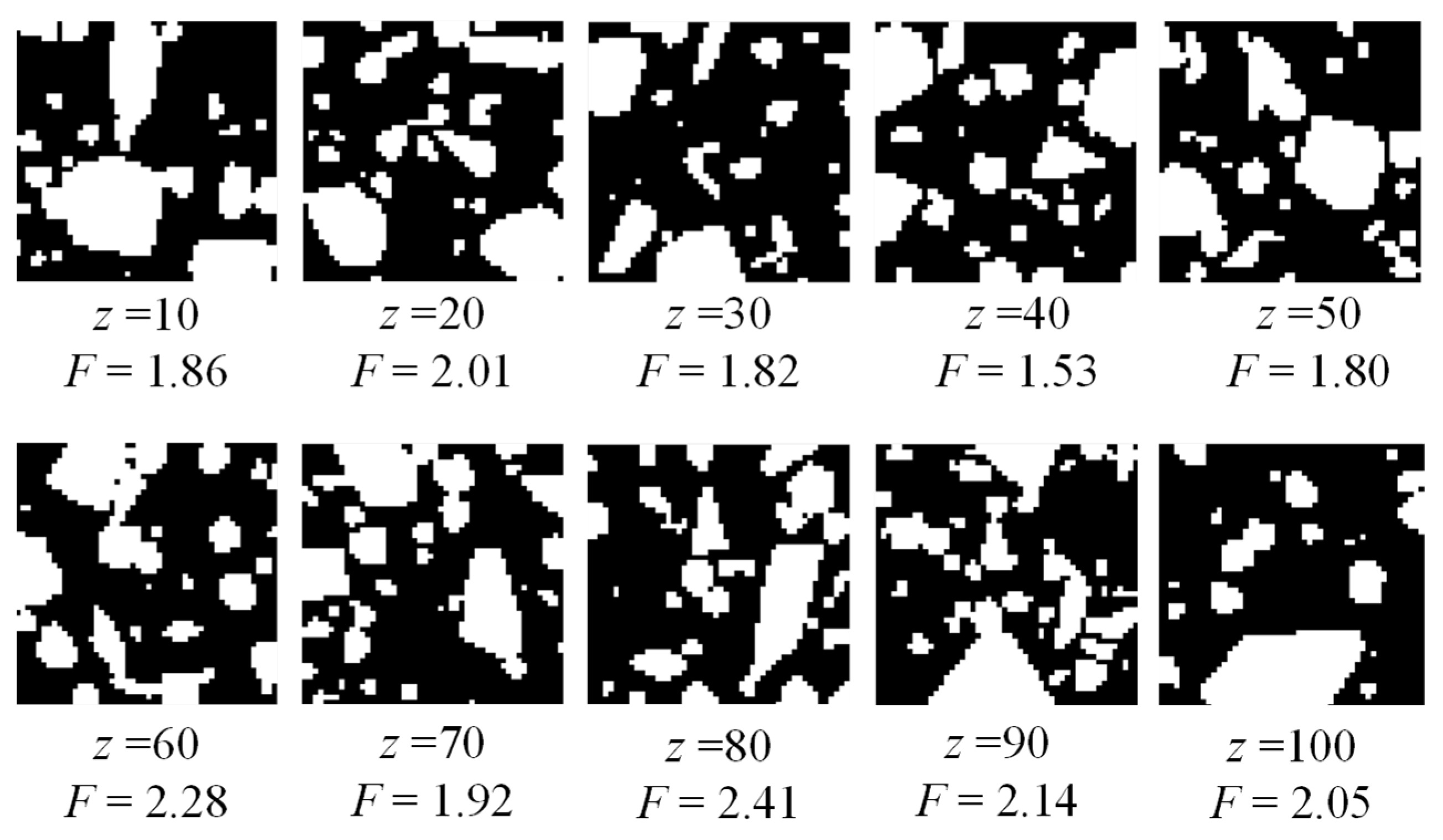
3.5. Fractal Dimension Calculation of the Generated SRM Cross-Section

After generating a trial mesostructure, the next step is to check if the fractal dimension of the cross-sections in different depths is close to the value tested from the in situ SRM site. To calculate the fractal dimension of the cross-sections of the generated mesostructures, the generated structure was transformed into a 3D matrix that uses 0 and 1 to represent the soil and rock areas. The transformed matrix in different depths is shown in Figure 7. In Figure 7, z represents the elevation of the cross-section, and the black and white areas represent the regions of soil and rock grains, respectively.
The fractal dimension was calculated with the same method of calculating the fractal dimension of the 2D processed image in Section 2. The fractal dimension of the cross-sections in different depths was calculated first; then, the average of these fractal dimensions was used as the overall value for the generated model.

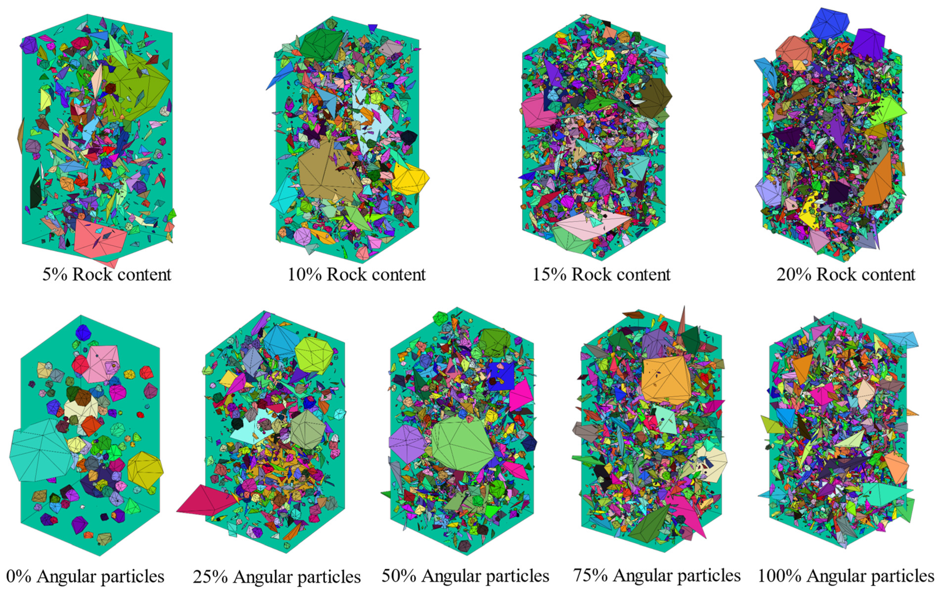
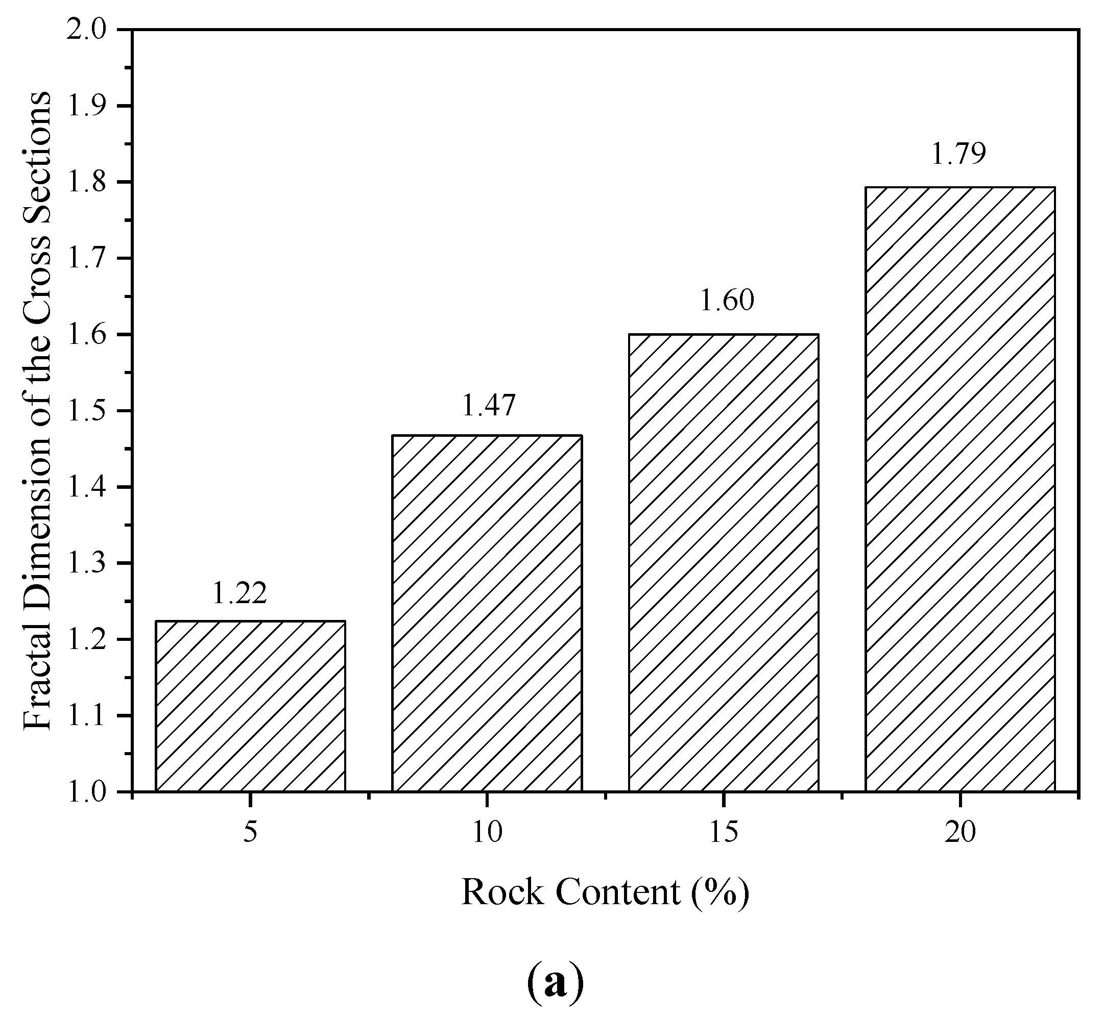
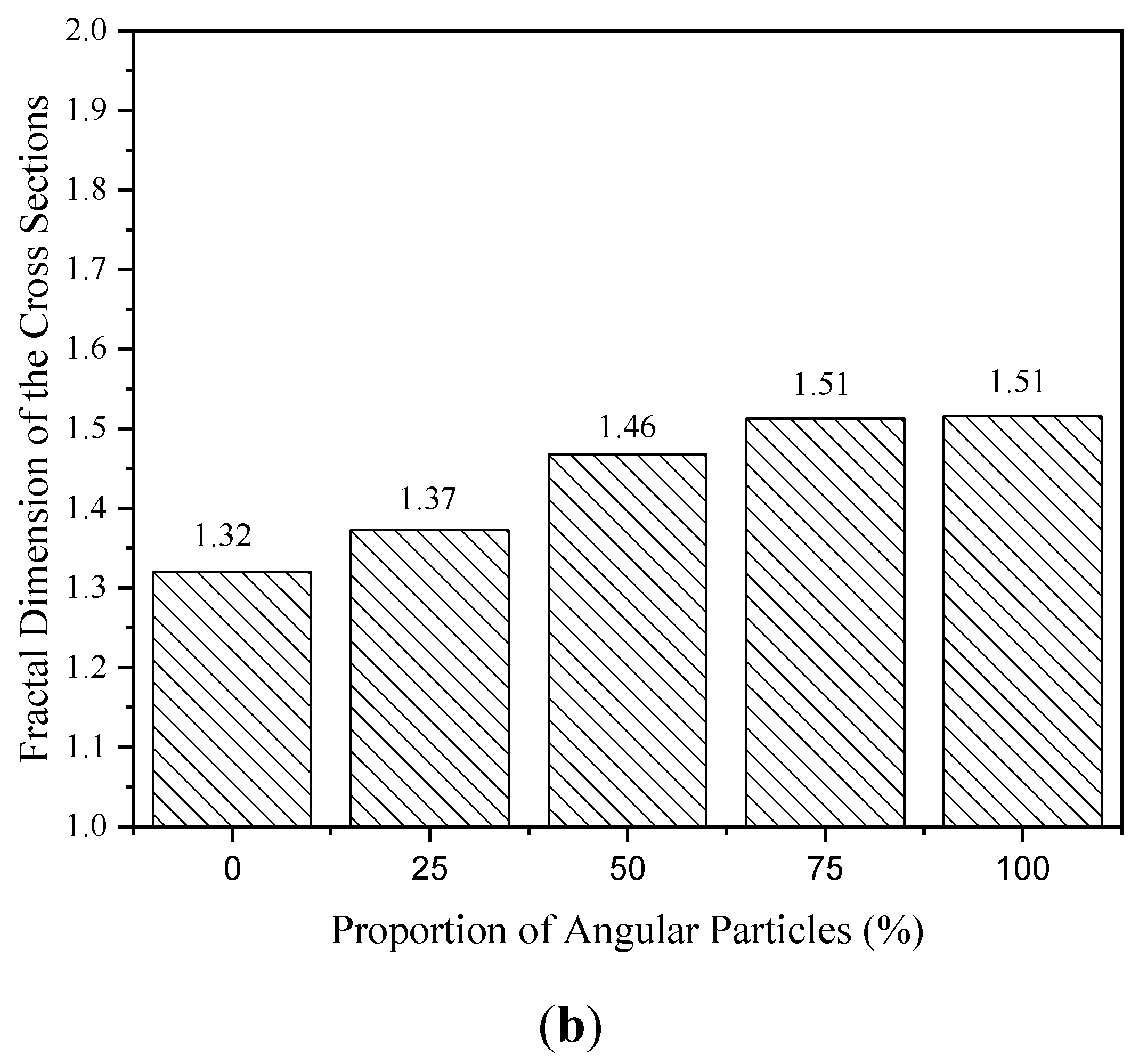
4. Influence of Rock Content and Shape on the Fractal Dimension

The effect of the rock content and the rock grains’ shape on the fractal dimension of the cross-sections of the created mesostructure was investigated through parametric research. Different SRM mesostructures with various rock contents and shapes were produced based on the abovementioned algorithm. Following that, it was determined what the average fractal dimension of the cross-sections at various depths was.
The parametric study matrix of generating different mesostructures with varied rock contents and particle shapes is shown in Table 1. Both the overall rock content and the proportion of angular particles were investigated in the parametric study. The overall rock content represents how much volume the rock particles take in the overall rectangular block area, and the content of angular particles represents the volume proportion of rock particles with an angular shape on the overall rock content. Groups 1 to 4 investigated the influence of the rock content on the fractal dimension. The overall rock content varied from 5% to 20%, and the proportion of angular and rounded particles is 50%. Group 2 and Groups 6 to 8 have the same overall rock content, and the proportion of angular particles varied from 0 to 100%. Five mesostructures were created for each group with the same target rock content and particle shape to minimize random error during the generation process.
Figure 8 presents examples of the generated mesostructures with different rock contents and particle shapes. According to Figure 8, the number of rock grains increases as the rock component in the generated SRMs increases. Additionally, when the proportion of angular particles rises, so does the number of rock grains. This is because, for a given grain size, rounded particles have a bigger volume than angular particles, and as a result, there are more angular particles per unit volume than rounded particles.
Figure 9 depicts the relationship between the cross-sections of the generated SRMs’ rock content, angular particle proportion, and fractal dimension. It can be seen that the cross-sections’ fractal dimension rises linearly as the rock content rises. This conclusion is consistent with the finding in Figure 8. When the percentage of angular particles is less than 75%, the fractal dimension increases as the percentage of angular particles increases. The influence of the angular particle content on the fractal dimension of SRMs is minimal when the proportion of angular particles is higher than 75%. This conclusion indicates that the fractal dimension of generated SRM mesostructures could be adjusted by changing the proportion of angular particles.

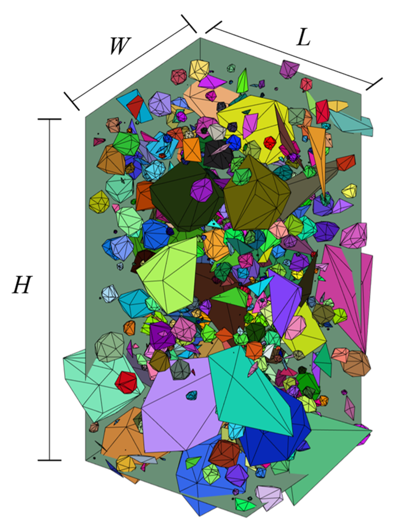
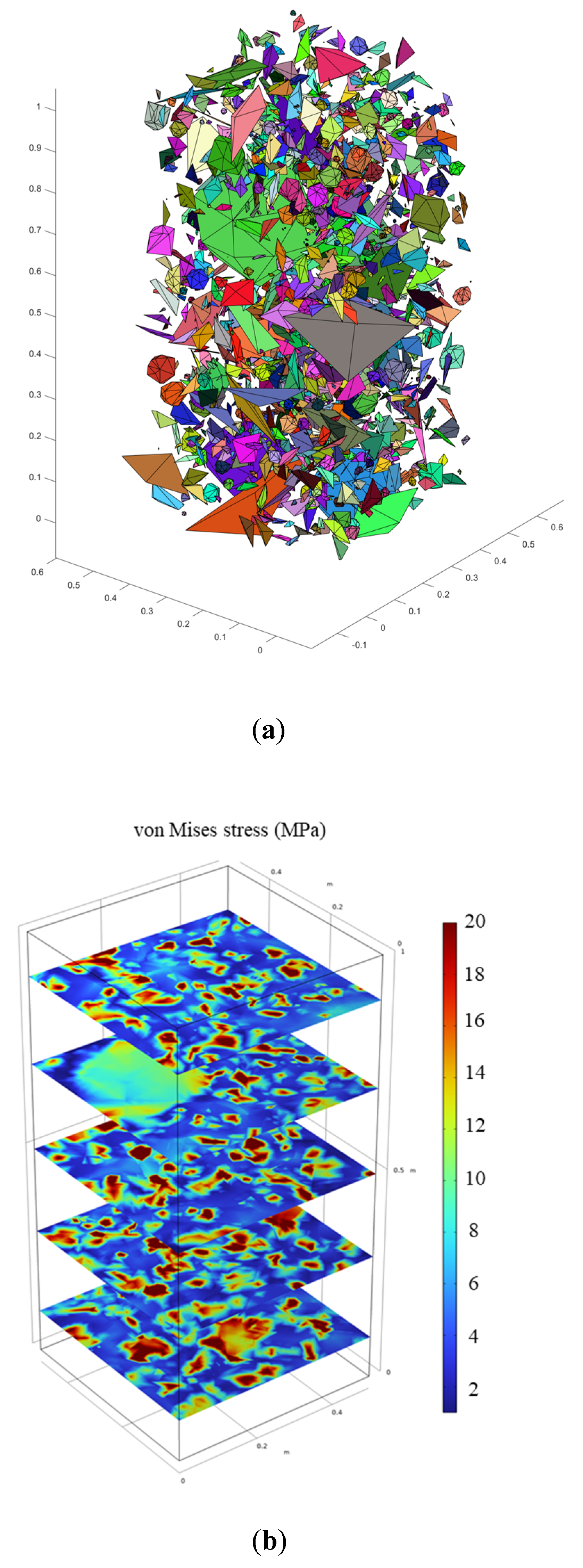
5. Examples of Numerical Modeling Based on the Proposed Algorithm

To evaluate the usability of the proposed mesostructure generation algorithm in the application of numerical modeling, an example of using the generated structure in finite element modeling is presented in this section. A random mesostructure was generated based on the proposed algorithm, as shown in Figure 10a. In total, 1466 rock particles were generated. The rock volume content of the tetrahedron particles was 5%, and the rock content of the rounded particles was 5%. The size of the numerical model was 0.5 m (length) by 0.5 m (width) by 1 m (height). The bottom of the model was fixed, and a 10 MPa uniaxial pressure was applied on the top surface of the model. To speed up the simulation process, the rock and soil particles were assumed to be linear elastic. The Young’s modulus was set as 4000 MPa for the rock particles and as 80 MPa for the soil domain. The Poisson’s ratio of both the rock and soil particles was assumed to be 0.3. The von Mises stress distribution under the uniaxial pressure is shown in Figure 10b.
As shown in Figure 10b, in the SRM mesostructure, most of the uniaxial load was carried by the rock skeleton, while the average von Mises stress in the soil domain was about 3 MPa. In addition, there was a stress concentration phenomenon on the edge of the rock particles, which verified the accuracy of the proposed mesostructure. However, it is worth noting that a more comprehensive constitutive model is needed to simulate the practical SRM responses under practical engineering.

6. Conclusions

This paper introduced a novel methodology that generates random mesostructures of SRMs based on the in situ information. The proposed mesostructure generation algorithm also incorporates existing methods for creating 3D SRMs and fully takes into account the in situ geometry parameters including size distribution, particle shape, and fractal dimension. In addition, the influence of the rock content and particle shape on the fractal dimension was investigated based on a parametric study. Based on the analysis conducted as part of this study, the following conclusions were drawn:
  • In contrast to earlier generation methods, the suggested method considers the fractal dimension and particle shape during generation. With the in situ SRMs, the suggested method reconstructs statistically similar mesostructures more reliably.
  • With an increase in rock content, the cross-sections of the produced mesostructure become more fractal in nature. This is because the number of particles increased with the increase in the rock content or angular particle proportion.
  • Only when the proportion of angular particles is less than 75% does the content have an impact on the fractal dimension. With an increase in the proportion of angular particles, the fractal dimension increases.

Author Contributions

Study conception and design, Z.L., H.Y., C.Z. and Z.Z.; data collection, Z.L. and G.L.; data analysis, Z.L., H.Y. and G.L.; draft manuscript preparation, Z.Z., Z.L. and C.Z. All authors reviewed the results and approved the final version of the manuscript.

Funding

The experiments described and the resulting data presented herein, unless otherwise noted, were funded by the Natural Science Foundation of Hebei Province (Grant No. E2021508026).

Institutional Review Board Statement

Not applicable.

Informed Consent Statement

Not applicable.

Data Availability Statement

The data supporting this study are included in the paper.

Conflicts of Interest

The authors declare that they have no known competing financial interests or personal relationships that could have appeared to influence the work reported in this paper.

References

  1. Xu, W.-J.; Yue, Z.-Q.; Hu, R.-L. Study on the mesostructure and mesomechanical characteristics of the soil-rock mixture using digital image processing based finite element method. Int. J. Rock Mech. Min. Sci. 2008, 45, 749–762. [Google Scholar] [CrossRef]
  2. Luan, B.; Zhou, W.; Meng, X.; Lu, X.; Liu, Z. Study on Permeability of Soil-Rock Mixture in Water-Blocking Layer of Open-Pit Coal Mine Dump Site. Adv. Civ. Eng. 2020, 2020, 1925849. [Google Scholar] [CrossRef]
  3. Yang, G.-Q.; Liu, H.; Zhou, Y.-T.; Xiong, B.-L. Post-construction performance of a two-tiered geogrid reinforced soil wall backfilled with soil-rock mixture. Geotext. Geomembr. 2014, 42, 91–97. [Google Scholar] [CrossRef]
  4. Gao, W.-W.; Gao, W.; Hu, R.-L.; Xu, P.-F.; Xia, J.-G. Microtremor survey and stability analysis of a soil-rock mixture landslide: A case study in Baidian town, China. Landslides 2018, 15, 1951–1961. [Google Scholar] [CrossRef]
  5. Zhou, Z.; Yang, H.; Wang, X.; Liu, B. Model Development and Experimental Verification for Permeability Coefficient of Soil–Rock Mixture. Int. J. Geomech. 2017, 17, 04016106. [Google Scholar] [CrossRef]
  6. Medley, E.W. Orderly characterization of chaotic Franciscan Melanges. Eng. Geol. 2001, 19, 20–32. [Google Scholar]
  7. Zhang, H.-Y.; Xu, W.-J.; Yu, Y.-Z. Triaxial tests of soil-rock mixtures with different rock block distributions. Soils Found. 2016, 56, 44–56. [Google Scholar] [CrossRef] [Green Version]
  8. Dong, H.; Peng, B.; Gao, Q.-F.; Hu, Y.; Jiang, X. Study of hidden factors affecting the mechanical behavior of soil–rock mixtures based on abstraction idea. Acta Geotech. 2021, 16, 595–611. [Google Scholar] [CrossRef]
  9. Coli, N.; Berry, P.; Boldini, D.; Bruno, R. The contribution of geostatistics to the characterisation of some bimrock properties. Eng. Geol. 2012, 137–138, 53–63. [Google Scholar] [CrossRef]
  10. Afifipour, M.; Moarefvand, P. Mechanical behavior of bimrocks having high rock block proportion. Int. J. Rock Mech. Min. Sci. 2014, 65, 40–48. [Google Scholar] [CrossRef]
  11. Kalender, A.; Sonmez, H.; Medley, E.; Tunusluoglu, C.; Kasapoglu, K. An approach to predicting the overall strengths of unwelded bimrocks and bimsoils. Eng. Geol. 2014, 183, 65–79. [Google Scholar] [CrossRef]
  12. Wang, Y.; Li, C.; Hu, Y. Use of X-ray computed tomography to investigate the effect of rock blocks on meso-structural changes in soil-rock mixture under triaxial deformation. Constr. Build. Mater. 2018, 164, 386–399. [Google Scholar] [CrossRef]
  13. Qian, J.; Yao, Y.; Li, J.; Xiao, H.; Luo, S. Resilient Properties of Soil-Rock Mixture Materials: Preliminary Investigation of the Effect of Composition and Structure. Materials 2020, 13, 1658. [Google Scholar] [CrossRef] [PubMed] [Green Version]
  14. Meng, Q.; Wang, H.; Xu, W.; Zhang, Q. A coupling method incorporating digital image processing and discrete element method for modeling of geomaterials. Eng. Comput. 2018, 35, 411–431. [Google Scholar] [CrossRef]
  15. Meng, Q.; Wang, H.; Xu, W.; Cai, M. A numerical homogenization study of the elastic property of a soil-rock mixture using random mesostructure generation. Comput. Geotech. 2018, 98, 48–57. [Google Scholar] [CrossRef]
  16. Chen, L.; Yang, Y.; Zheng, H. Numerical study of soil-rock mixture: Generation of random aggregate structure. Sci. China Technol. Sci. 2018, 61, 359–369. [Google Scholar] [CrossRef]
  17. Xu, W.-J.; Zhang, H.-Y.; Jie, Y.-X.; Yu, Y.-Z. Generation of 3D random meso-structure of soil-rock mixture and its meso-structural mechanics based on numerical tests. J. Cent. S. Univ. 2015, 22, 619–630. [Google Scholar] [CrossRef]
  18. Sheng, P.; Zhang, J.; Ji, Z. An advanced 3D modeling method for concrete-like particle-reinforced composites with high volume fraction of randomly distributed particles. Compos. Sci. Technol. 2016, 134, 26–35. [Google Scholar] [CrossRef]
  19. Meng, Q.; Wang, H.; Cai, M.; Xu, W.; Zhuang, X.; Rabczuk, T. Three-dimensional mesoscale computational modeling of soil-rock mixtures with concave particles. Eng. Geol. 2020, 277, 105802. [Google Scholar] [CrossRef]
  20. Yao, Y.; Li, J.; Ni, J.; Liang, C.; Zhang, A. Effects of gravel content and shape on shear behaviour of soil-rock mixture: Experiment and DEM modelling. Comput. Geotech. 2022, 141, 104476. [Google Scholar] [CrossRef]
  21. Bergen, G.V.D. A fast and robust GJK implementation for collision detection of convex objects. J. Graph. Tools 1999, 4, 7–25. [Google Scholar] [CrossRef]
  22. Kockara, S.; Halic, K.; Iqbal, K.; Bayrak, C.; Rowe, R. Collision Detection: A Survey. In Proceedings of the 2007 IEEE International Conference on Systems, Man and Cybernetics, Montreal, QC, Canada, 7–10 October 2007. [Google Scholar]
Figure 1. Digital image processing steps of the in situ SRM image.
Fractalfract 06 00570 g001
Figure 2. Flowchart of the mesostructure generation process.
Fractalfract 06 00570 g002
Figure 3. Generation process of angular grains: (a) generate the base tetrahedron; (b) generate a new vertex on the triangle with the largest surface area; (c) generate a new tetrahedron based on the newly generated vertex.
Fractalfract 06 00570 g003
Figure 4. Generation process of rounded grains: (a) randomly create intersecting circles; (b) randomly select points within the intersected circle and add offset; (c) connect all generated vertices and form the grains.
Fractalfract 06 00570 g004
Figure 5. Example of the generated SRM mesostructure.
Fractalfract 06 00570 g005
Figure 6. Examples of using Minkowski differences to determine convex shapes collision: (a) example of intersecting shapes; (b) example of nonintersecting shapes.
Fractalfract 06 00570 g006aFractalfract 06 00570 g006b
Figure 7. Cross-sections of the generated SRM mesostructure in different depths and their fractal dimension.
Fractalfract 06 00570 g007
Figure 8. Examples of generated mesostructures with different rock contents and particle shapes.
Fractalfract 06 00570 g008
Figure 9. Relationship between the rock content (a) and angular particle proportion (b) with the fractal dimension of the mesostructure cross-section.
Fractalfract 06 00570 g009aFractalfract 06 00570 g009b
Figure 10. Examples of numerical simulation based on the proposed algorithm: (a) generated mesostructure; (b) von Mises stress under a uniaxial pressure.
Fractalfract 06 00570 g010
Table 1. Study matrix of generating different mesostructures with varied rock contents and particle shapes.
Size Range
(cm)
Angular Particles ContentRounded Particles ContentOverall Rock Content (%)
Group No. 5–1010–1515–205–1010–1515–20
1110.5110.55
222122110
3331.5331.515
444244220
500044210
6110.5331.510
7331.5110.510
844200010
Publisher’s Note: MDPI stays neutral with regard to jurisdictional claims in published maps and institutional affiliations.

