Article

An Experimental Approach towards Motion Modeling and Control of a Vehicle Transiting a Non-Newtonian Environment

1
Automation Department, Technical University of Cluj-Napoca, 400114 Cluj-Napoca, Romania
2
Dynamical Systems and Control Research Group, Ghent University, B-9052 Ghent, Belgium
3
Core Lab EEDT, Flanders Make Consortium, B-9052 Ghent, Belgium
4
Civil Engineering Department, Technical University of Cluj-Napoca, 400114 Cluj-Napoca, Romania
*
Author to whom correspondence should be addressed.
The authors contributed equally to this work.
Fractal Fract. 2021, 5(3), 104; https://doi.org/10.3390/fractalfract5030104
Submission received: 12 July 2021 / Revised: 13 August 2021 / Accepted: 20 August 2021 / Published: 25 August 2021
(This article belongs to the Special Issue Fractional Dynamics 2021)

Abstract

:
The present work tackles the modeling of the motion dynamics of an object submerged in a non-Newtonian environment. The mathematical model is developed starting from already known Newtonian interactions between the submersible and the fluid. The obtained model is therefore altered through optimization techniques to describe non-Newtonian interactions on the motion of the vehicle by using real-life data regarding non-Newtonian influences on submerged thrusting. For the obtained non-Newtonian fractional order process model, a fractional order control approach is employed to sway the submerged object’s position inside the viscoelastic environment. The presented modeling and control methodologies are solidified by real-life experimental data used to validate the veracity of the presented concepts. The robustness of the control strategy is experimentally validated on both Newtonian and non-Newtonian environments.

1. Introduction

Non-Newtonian fluid dynamics properties are encountered in multiple fields such as physics, medicine, biology, and industrial manufacturing. Several steel manufacturing techniques require the motion of particles inside the non-Newtonian steel framework stirred through electromagnetic actuation [1]. Another application of significant relevance is the rising domain of targeted drug delivery. This concept consists of a nanorobot traveling inside the blood vessels to detect possible problematic areas caused by cholesterol deposits, atherosclerosis, thrombophlebitis, aneurysm, or blood clots [2,3]. Apart from problem detection, the robot can also release a treatment substance to treat the specified area. The benefits brought by the targeted treatment include reduced side effects, faster action, and less substance intoxicating the body when compared to classical medicine treatment options [4,5].
The carrier object should maintain a fixed position inside the venous habitat until the full substance administration is performed. This paper provides the tuning of a fractional order controller with the purpose of navigating and stationing at the desired position in a non-Newtonian blood environment, which can be associated with blood.
The focus of the present study is the development and experimental validation of a fractional order model that captures the interaction between a non-Newtonian environment and a submerged object. To begin with, an integer order model is formulated for objects transiting through Newtonian fluids, using available information regarding underwater propulsion on submarines in maritime environments. The initial integer order navigation model is a simplified model, capturing only essential aspects of Newtonian fluid submersion. Furthermore, the model is calibrated on experimental data acquired from a custom built platform that mimics non-Newtonian conditions inside the cardiovascular framework, obtaining a generalized fractional order model. The obtained fractional order model for non-Newtonian submersion is based on fractional calculus, a powerful tool used to accurately express memory based material dynamics and biological phenomena. The purpose of the fractional order representation is to encompass complex motion dynamics within a transfer function that has a reduced number of parameters but an increased complexity. Hence, the initial model is roughly obtained and serves as the starting point in the search for a more complex and accurate fractional order model, which ultimately will capture high order characteristics and various physical aspects that have been neglected throughout the development of the initial navigation model. The available specialized literature is abundant on the suitability of fractional calculus to properly define physical phenomena such as the memory based viscoelasticity and shear stress found in non-Newtonian singularities [6,7,8]. In addition, fractional calculus is a powerful tool in biomedical studies such as epidemiological modeling of different infections [9,10,11,12].
The novelty of this paper is related to the modeling and control of non-Newtonian interactions from an experimental perspective. Modeling non-Newtonian system dynamics has been realized using complex Navier–Stokes equations in [13]. The aim of the current study is to exclude complex fractional order differential equations for system identification by employing an experimental approach. The process modeling is based on generalizing already available Newtonian interaction models to non-Newtonian motion models using experimental data acquired from a custom built platform. The obtained model is successfully validated in the non-Newtonian setting, and a fractional order motion controller is developed. Moreover, the non-Newtonian control strategy is validated experimentally, proving the suitability of fractional calculus for both modeling and control purposes. Finally, the versatility of the experimental platform through environmental changes allows a robustness analysis of the controller in various types of liquids, both Newtonian and non-Newtonian, representing another novel aspect of the study.
The relevance of the study is widespread through a multitude of research fields connected to non-Newtonian interactions such as pharmaceutical process control, biomedical fields, manufacturing of viscous substances, and non-Newtonian fluid navigation, etc. [1,4,6,14,15,16,17,18].
The paper is structured as follows. Section 2 describes the custom built experimental platform that simulates non-Newtonian vascular conditions as well as the autonomous submerged vehicle capable of cruising thorough the environment. Section 3 presents motion dynamics modeling of a submerged object starting from Newtonian dynamics which are extended towards the generalized non-Newtonian dynamics framework. Section 4 provides information regarding the chosen tuning procedure for the fractional order PD controller as well as the motivation behind choosing the design specifications. The proposed modeling and control strategies are customized for the experimental setup presented in Section 2 by developing a dedicated model for the motion of the submerged vehicle in the venous habitat and controlling its position throughout the environment in Section 5. This section also features experimental validation of the proposed methodology, solidifying the presented concepts. Section 6 concludes the study by briefly emphasizing the relevance of the obtained results in the non-Newtonian field.

2. Experimental Non-Newtonian Environment Framework

Fluids such as ice-water, petrol-water, liquid detergents, etc., can be introduced in a custom built experimental setup to test the relevance of several modeling and control approaches in non-Newtonian frameworks. The versatile setup encapsulates the dynamics of a moving object, suspended in a non-Newtonian fluid, with data measurements and control regarding the object’s motion dynamics.
For this particular study, the experimental unit has been configured to mimic the cardiovascular system. The challenges encountered by a substance carrier device inside the cardiovascular environment with the purpose of targeted drug delivery are recreated inside the custom built platform. The setup can be divided into two main parts: the cardiovascular resemblance exhibiting characteristics similar to human blood, including the blood flow profile as well as non-Newtonian traits, and the carrier device capable of transiting and analyzing the impedance of the non-Newtonian environment. The framework is used for calibrating and validating a generalized model for sunken advancement of the robot in non-Newtonian conditions and for testing different control strategies for position control of the robot.

2.1. Non-Newtonian Cardiovascular Homology

The vascular homology is illustrated in Figure 1. The circuit is a sealed environment that houses the non-Newtonian fluid which is recirculated using a variable flow pump, SPXFLOW BL70-EB. A periodic blood flow hemodynamic profile is implemented based on the research presented in [19]. The blood flow characteristic is programmed using a real-time myRIO controller and LabVIEW programming. Two small reservoirs are used for robot insertion and extraction and also for completely sealing the circuit. The reservoirs are connected by two pipes of different diameters resembling an artery and a vein, respectively. Additionally, passing between the two venous items is realized, and the robot is capable of navigating in both directions, mimicking the transition between an artery and a vein, and vice versa.
Fabric conditioner with similar blood characteristics has been used inside the venous system with viscosity of μ = 0.085 × 10 5 kg/ms, density ρ = 1.03 / 100 kg/m 3 , and pulsation frequency ω = 2 π 7 / 6 .
During real-life blood flow scenarios, the vessels slightly expand and contract [20,21]. The experimental framework aims to also encapsulate the vessel expansion and contraction properties. Hence, the two tubes representing the vein and artery are made of polyurethane with steel insertions. During experiments, the metal insertions obtain a certain flexibility of the pipe’s wall. The insertion density ρ c a r t = 1.14 × 10 3 kg/m 3 is the same for both tubes.
The properties of the larger tube are diameter D = 160 / 1000 m, wall thickness h = 0.9 / 1000 m, and a ratio between soft and hard metal insertions of κ = 0.9 , while for the small tube, D = 102 / 1000 m, h = 0.9 / 1000 m, and κ = 0.1 .

2.2. Autonomous Submerged Vehicle

A robot capable of transiting the cardiovascular resemblance unit has been designed, built, and programmed to achieve a single purpose: efficient targeted drug delivery at a given area in need of treatment.
The design of the submersible is inspired by autonomous underwater vehicles, reduced size submarines capable of autonomously traveling and recording underwater data [22]. The aquadynamic carcass has been 3D printed such that it has a symmetrical ellipsoidal shape with length of 0.09 m and width of 0.03 m (Figure 2).
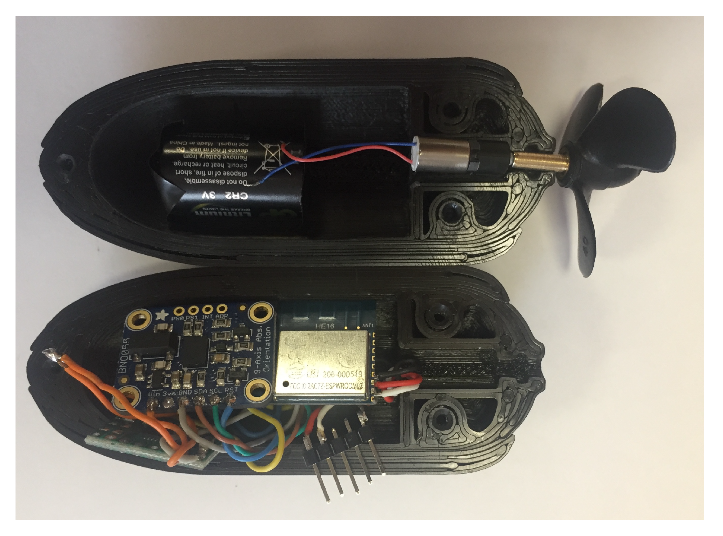
Inside the hull, there is a hollow for the embedded electronics that ensure proper functionality. The main brain of the robot consists of the ESP8266 module, a WiFi module and microcontroller used to manage individual modules such as: inertial measurement unit, impedance measurement unit, DC motor command unit, and WiFi communication logic (Figure 3).
For the intertial measurement unit, the BNO055 9 degrees of freedom sensor has been chosen to measure the real-life acceleration of the body. The acceleration data are processed by the robot’s microcontroller and transformed into velocity and position with a sampling frequency of 100 Hz. A solution of the well-studied problem of accumulating measurement errors that cause a slow drift to infinity when transforming acceleration data to position measurement is presented in [23]. The positioning algorithms are implemented inside the submersible, and the data are processed locally. This is done with the purpose of providing autonomous feedback for position control without the need of an external server. Positioning data are provided to the server only for analysis purposes. Multiple tests of different time lengths show experimentally that the algorithms presented in [23] provide accurate positioning measurements.
The submersible is equipped with a 6 mm DC motor attached to a 40 mm Graupner three-blade propeller. The DC motor is rotated by giving a voltage between 0 and 5 V through the pulse width modulation (PWM) technique.
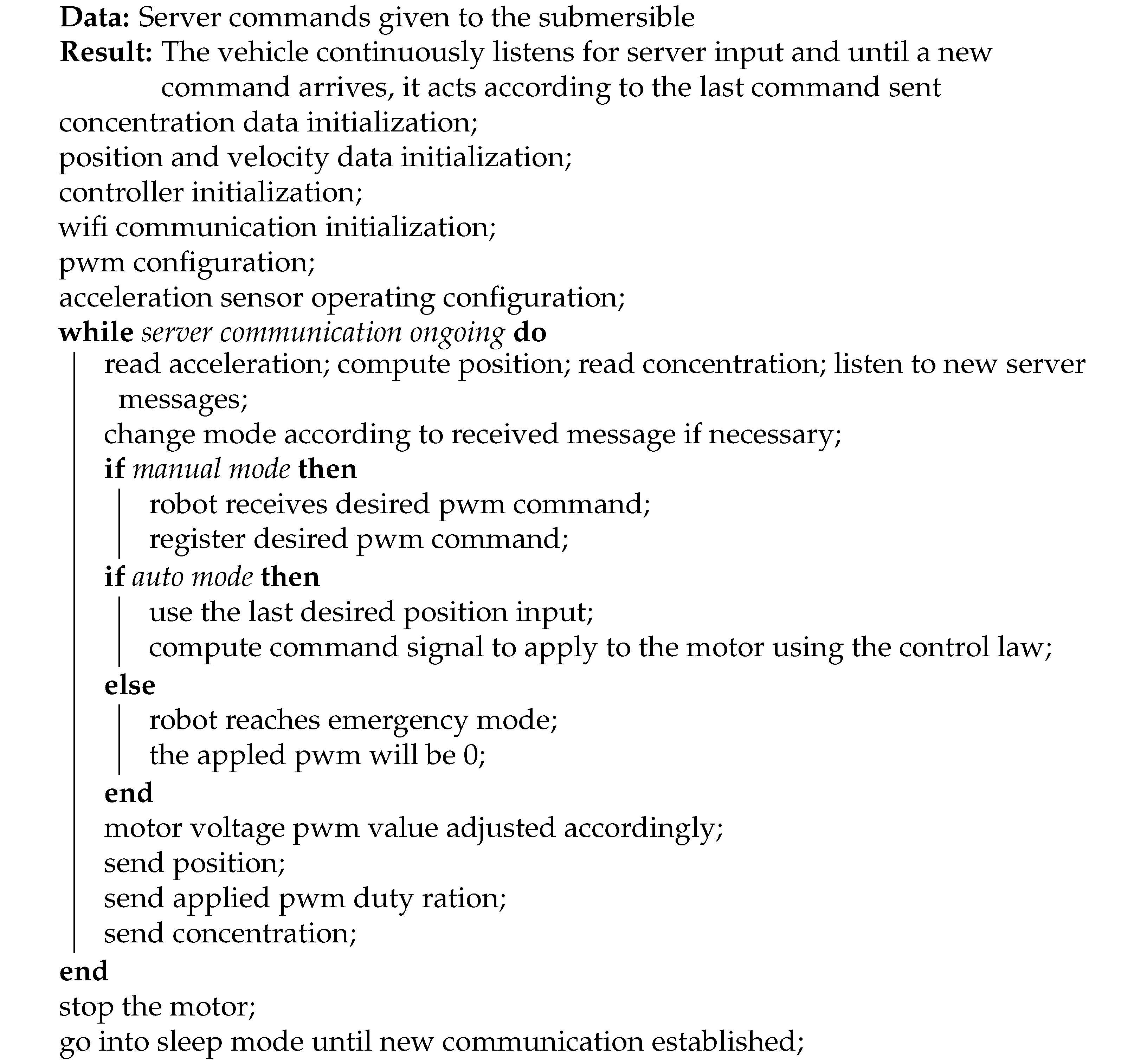
The WiFi module is used for communication with an external server used for logging and analyzing data. A secure communication through the TCP/IP protocol is used to send the computed position and impedance information of the environment. The robot can operate in manual, automatic or emergency modes. For the manual operating mode, the server sends the command value (PWM duty ratio) for the DC motor, and the robot cruises with a constant propeller rotation. In auto mode, the server sends a desired position, and the robot navigates towards it, computing the necessary PWM duty ratio following a control law. The emergency procedure overrides the aforementioned functioning possibilities in order to suddenly stop the motion of the submersible.
The submersible is equipped with a single propeller and has no side propellers for steering since the circulatory system does not present any bending. This is a prototype still in its infancy, and its main purpose is to validate non-Newtonian interactions from modeling and control points of view. The experimental platform was built to encompass only essential aspects in order to successfully study fractional order and control in non-Newtonian fluids.
Even if bending has not been taken into consideration, the tube walls act as a guide for the submersible’s motion, allowing it to move between the two tubes. Future developments include altering the experimental platform to include bending as well as extensions of the present algorithm.
More information regarding the software implementation used for the submersible is detailed in Appendix A.

2.3. Environmental Impedance Variation Detection

The authors of [24,25] use electrical impedance measurement to analyze different properties regarding blood chemical concentration with biomedical purposes. An environmental analysis can be performed in the non-Newtonian fluid with the help of a sensor that measures the liquid’s impedance while the robot is transiting the veins. The actual values of impedance are not of significant relevance, but the emphasis is on detecting environmental changes that signal a problematic area in need of localized treatment. The data offered by the sensor setup are logged together with the position information using the same sampling time of 10 ms.
The chosen sensor to fulfill the task is the Dropsens DS550 screen printed electrode. The sensor has been designed for clinical analysis regarding saliva glucose concentration. The device is suitable for chemical analysis performed on microvolumetric samples, as well as full liquid submersion. The sensor’s reduced dimensions ( 3.4 cm × 1.0 cm ×   0.005 cm) allow the attachment to the surface of the robot. The sensor data are read and analyzed by the same microcontroller, ESP8266.
Experimental tests have been performed to detect impedance differences among the liquid. In order to simulate these differences, a mixture of glucose and the non-Newtonian fluid has been inserted in certain points of the venous system. Several experimental measurements are presented in Appendix B.
The applicability in the biomedical domain of impedance sensing can be useful in any targeted treatment, depending on the substance that is being transported by the robot, e.g., AHRO-001 for cholesterol deposits [26].

2.4. Submersible Miniaturization Possibilities

The purpose of this study is to provide a framework to analyze the interaction between the moving object and the non-Newtonian fluid. The concepts are proven at a large scale, and the current dimension of the submersible is far from reaching targeted drug delivery sizing. Non-Newtonian fluid dynamics analysis is an emerging topic, one of the novelties of this study being the accessible experimental setup which is affordable and easy to reproduce.
The current submersible sizing is justified by the desire to build the setup by entirely using widely available components at a reasonable price. In addition, the microcontroller has been chosen to be easily programmed using the Arduino IDE, a popular programming language based on C, a lighter alternative to embedded C programming that is studied mostly by students with electrical oriented degrees. The motivation behind this choice is the ease of reproduction for research and education. An analysis regarding the versatility of the setup for educational purposes is presented in [27].
The main factors that influence the increased size of the submersible are the battery, the propeller, and the impedance sensor. The 40 mm propeller has been chosen such that the submersible is able to navigate counter currents, which is not needed for the current purpose of the setup. The DC motor has a reduction box in order to be able to spin the large propeller, which can be eliminated when the propeller size is reduced. Another aspect that adds to the overall sizing is the 3D printed hull featuring sturdy walls with a thickness of approximately 4 mm. The increased wall thickness ensures that the two halves of the case can be dismounted and re-glued without damage, for easy access to the components during the development and testing phase of the submersible. Since the submersible has reached its final version both from design and programming perspectives, the hull’s thickness can be drastically reduced.
Reducing the size of the submersible to 15 mm in length and 8 mm in width can be realized by replacing the current ESP8266 microcontroller with a dedicated printed circuit board (PCB), changing the CR123A battery with a smaller sized 3.3 V alternative, eliminating the motor’s reduction box, and reducing the propeller’s diameter from 40 mm to 8 mm. The battery will always be a critical element inside the robot because it can produce damage through heating. An alternative to the battery is the usage of a supercapacitor [28]. Wi-Fi can be replaced by Bluetooth low energy (BLE) for energy efficiency, and the 3D printed hull will be realized through Teflon injection [29] or milling. The advantage of this approach is that the design of the submersible is similar to the current solution. However, the drawback is that the cost for a prototype is increased, as well as the need to order custom made PCBs, instead of simply buying the components.
Further dimension reduction can be performed in the 1–2 mm scale. In this scenario, the entire propulsion system must be completely redesigned. The motor and the propeller should be replaced with piezoelectric materials (the most popular being Lead Zirconate Titanate) or any other material that produces vibration through deformation. The submersible’s movement concept is based on propellant-less thrusting of the object using vibration [30,31]. Apart from complete redesign of the propeller, the battery is also replaced by an energy harvesting circuit of reduced size. Multiple options are available based on temperature, vibration, chemicals, etc., such as those detailed in [32]. Furthermore, the impedance sensor is replaced by printed electro-mechanical cells of nanometer dimensions [33]. In this scenario, the submersible’s dimension fits the targeted drug delivery paradigm. However, producing a single prototype is difficult with costs spanning in thousands of euros, making the platform scarcely accessible for educational purposes.
A feasibility study is performed on the current non-Newtonian platform in [13], proving the platform’s scalability. The discovered non-Newtonian properties hold at larger or smaller scales. Hence, the current non-Newtonian interactions modeled throughout this paper are also valid if the prototype is scaled differently than the one presented in the current study.

3. Motion Dynamics Modeling for Submerged Objects in a Non-Newtonian Environment

Viscoelasticity is one of the main properties of materials exhibiting non-Newtonian behavior that require fractional order equations to properly represent the dynamics of submerged non-Newtonian motion [6]. Equations such as the Mittag–Leffler function or Navier–Stokes equations can be found in the literature to handle the fractional dynamics of viscoelastic flow of blood, polymers, or other non-Newtonian materials [34,35,36]. Hitherto, there is no relevant work found that handles the problem of positioning in non-Newtonian environments based on a solid experimental background. The improvement the present paper brings to the field of non-Newtonian motion dynamics is the experimental approach it offers both through the built experimental platform and through the process’s fractional order identification experimental approach. In addition, apart from developing the non-Newtonian navigation model, the experimental approach also captures particularities of the custom built setup that cannot be included in the previously mentioned analytical models, such as the connection between the two tubes of different diameters, the expansion and contraction of the flexible tubes acting as blood vessels, and the effect of the pump.
Obtaining an accurate model for the submersible’s non-Newtonian motion dynamics has been realized using a two-step approach. Firstly, we develop a general navigation model for the dynamics of the robot based on submerged motion equations widely available for Newtonian habitats [37,38,39], leading to an integer order process model. Consequently, we include the non-Newtonian habitat singularities by searching for a fractional order motion dynamics model using optimization techniques to minimize the mean squared error between the experimental step response and a candidate fractional order model. The integer order model obtained in the first step is the pivot point for the minimization procedure, guaranteeing that the obtained fractional order model has physical relevance in the submerged viscoelastic environment.

3.1. Developing a General Navigation Model for Submerged Objects in a Newtonian Setting

Figure 4 shows a free body diagram of a fully submerged robot with surge motions along the X axis. The center of gravity is considered in the centroid of volume, the object’s geometric center. The thrust force is generated by the propulsion unit that pushes the submersible forward, whereas the drag force acts opposite to the relative motion of the body with respect to the moving fluid. The weight is the downward force acting upon the robot created by the gravitational acceleration and the object’s mass. According to Archimede’s principle, the buoyancy force is equal to the weight of the fluid displaced by the moving body.
Navigation equations related to large scale submarines operating in Newtonian fluids are developed by [40,41] based on nonlinear equations. A single-propeller submarine’s navigation model is developed starting from the following equation:
( M R B + M A ) ν ˙ + ( C R B + C A ) ν + ( D l + D n ) ν = τ ,
representing the general navigation model for large scale submarines [42], where M R B , M A , C R B , C A , D l , and D n are matrices representing the inertia of the rigid body, added mass, rigid centripetal and Coriolis forces, hydrodynamic centripetal and Coriolis force, linear damping, and nonlinear damping. The matrices are formulated for a three degree of freedom submarine: surge (u)—motion on the X axis, sway (y)—motion on the Y axis, and heave—motion on the Z axis.
M R B = m 0 0 0 m 0 0 0 m
M A = X u ˙ 0 0 0 Y v ˙ 0 0 0 Z w ˙
C R B = 0 0 m v 0 0 m u m v m u 0
C A = 0 0 Y v ˙ v 0 0 X u ˙ u Y v ˙ v X u ˙ u 0
D l = X u 0 0 0 Y v 0 0 0 Z w
D n = X | u | u | u | 0 0 0 Y | v | v | v | 0 0 0 Z | w | w | w |
The matrices describing the navigation model from (1) depend on the velocities u—surge, v—sway, and w—heave. ( X , Y , Z ) denote the forces decomposed in the body’s reference frame. X u , X v , X w , Y x , Y v , Y w , Z u , Z v , a n d   Z w represent the forces decomposed on the three axes of the reference plane.
The propeller’s torque and thrust are expressed through τ , while the submarine’s velocity vector is given by ν .
The velocity vector can be written as a dependence of velocities on the X axis u, Y axis v, and Z axis r as expressed by
ν = [ u v r ] T .
The emphasis for the navigation model is on the X axis while ignoring the other two axes due to the design characteristics of the constructed experimental platform in the initial analytical development. However, for the experimental calibration of data, all forces, breaking effects, and the influence of the non-Newtonian fluid are taken into consideration to develop the fractional order data. The integer order model is only a starting point for the search of a fractional order model that encapsulates all the dynamics.
Making the velocity equation on the X axis linear around a working point denoted by u 0 for the X axis gives the linear velocity equation
ν = ν 0 + Δ ν = [ u 0 + Δ u 0 0 ] T .
Replacing the linear velocity around a working point u 0 of a submarine with mass m gives
Δ T h = [ 2 u 0 X | u | u X u 0 0 ] Δ ν + [ m X u ˙ 0 0 ] Δ ν ˙ ,
leading to the transfer function connecting the thrust generated by the propeller and submarine’s velocity
H ( s ) = Δ U ( s ) Δ T h ( s ) = 1 ( m X u ˙ ) s 2 u 0 X | u | u X u ,
with X u ˙ (kg/m) representing the surge added mass coefficient along the X axis
X u ˙ = 4 β ρ π 3 ( d 2 ) 2 ,
the force component decomposed in the body’s frame X u (kg/s)
X u = ρ V A f C d
and the surge drag coefficient X | u | u (kg s) generated by the robot’s body
X | u | u = 1 2 ρ C d A f .
The density of the operating fluid is denoted by ρ (kg/m 3 ), while the Newtonian liquid’s flow velocity vectorial magnitude is represented by V (m/s). The submarine’s hull shape influences the motion through the frontal area A f (m 2 ) and through β , an empirical parameter dependent upon the ellipsoidal properties of the shape. The motion is influenced also by propeller characteristics such as d (m) representing the diameter and the experimentally determined drag coefficient C d .
A single propeller placed in the center of the X axis, at the rear of the submarine, thrusts the vehicle forward with the following force T h ( N ) [43]:
T h = C t ρ A ( ω r ) 2 ,
where ω is the propeller’s angular velocity (rad/s), r is the radius (m), and
A = π d 2 / 4 .
The propeller’s angular velocity, ω , is influenced by the angular velocity of the motor acting upon it, which is determined by the voltage feeding the motor. A simple relation between the motor’s voltage and the propeller’s angular velocity can be written in the shape of a first order transfer function [44]
H m o t o r ( s ) = k m T m s + 1 ,
with k m and T m being the process’s gain and time constant, respectively.
An analytic linear Newtonian navigation model of a submerged object on the X axis is obtained as an integer order transfer function connecting the input voltage applied on the motor and the submarine’s velocity.
H I O ( s ) = k m C t ρ A r 2 ( T m s + 1 ) [ ( m X u ˙ ) s 2 u 0 X | u | u X u ] .
The condensed integer order navigation model can be written as
H I O V e l o c i t y ( s ) = k a 1 s 2 + a 2 s + a 3 .

3.2. Newtonian Model Calibration towards Non-Newtonian Feature Mitigation

The previous analytic model in the form of an integer order transfer function is relevant to characterize the motion of a submerged object in Newtonian circumstances. For non-Newtonian operating conditions, the condensed model presented in (19) should be extended in the generalized domain of fractional calculus in the following manner:
H F O V e l o c i t y ( s ) = k p b 1 s α + b 2 s β + b 3 ,
where k p is the proportional gain, b 1 , b 2 , b 3 are polynomial coefficients, and α , β denote fractional orders of differentiation, able to capture local material properties [8].
In order to determine the relevant fractional order model for the forward thrusting dynamics, the integer order model is calibrated on experimental step response data registered in the non-Newtonian framework. For the fractional order identification purposes, an input voltage is applied to the motor advancing the propeller, and the velocity is measured. A minimization criterion in the form of a cost function denoted by J is chosen to optimize the mean squared error between the data registered during the experiment and possible candidate models for the fractional order transfer function
J = min 0 | x m ( t ) x ( t ) | d x .
The fractional order parameters are optimized such that the difference between the experimental measurement at time t, denoted by x m ( t ) , and the response of the system to be identified, x ( t ) , is minimized.
As in any optimization algorithm, the pivot point from which the search is started is of significant relevance to the solution reached [45,46,47]. The chosen starting point to search for the solution is the determined Newtonian motion model described in the previous subsection. The initial values are given such that k p = k , b 1 = a 1 , b 2 = a 2 , and b 3 = a 3 and for the fractional orders α = 2 and β = 1 . Constraints are imposed for the search interval, parameter values, and the fractional orders tolerance in order to reduce computation time and to obtain a model with physical relevance. For reducing local minima occurrences, it is suggested to constrain the fractional orders in the maximal ranges of α ( 1 , 2 ) and β ( 0 , 1 ) intervals. The parameters k p , b 1 , b 2 , and b 3 must be > 0 , such that the model has physical relevance. The optimization can be performed using MATLAB’s optimization toolbox with the fmincon function. Different fmincon algorithms such as optim-set or trust-region-reflectiv should be tested on the same minimization problem in order to asses if the found solution is stuck in a local minima problem.
The velocity model of a vehicle transiting a Newtonian environment has been obtained in (19) using analytical equations described in Section 3.1 as a second order transfer function. The velocity transfer function is further generalized in (20), where the fixed orders of s, s 2 and s 1 , have been generalized to arbitrary orders denoted by α and β to include the complex dynamics of non-Newtonian submersion in the process model. The obtained model subsequent to the optimization procedure represents the motion dynamics of an object in a non-Newtonian habitat from the velocity point of view. In order to obtain the positioning dynamics, an integrator is added to the fractional order velocity from (20):
H F O P o s i t i o n ( s ) = k p s ( b 1 s α + b 2 s β + b 3 ) .

4. Motion Controller Development

Automatic control challenges for positioning processes consist of developing an efficient control strategy that provides zero steady state error, reduced settling time, fast disturbance rejection, and robustness. The fractional order model exhibiting the motion characteristics of submerged non-Newtonian interaction suggests the usage of fractional order control approaches, well known for offering more degrees of freedom and increased stability, while also satisfying a bigger range of design specifications than classical order controllers [48,49,50,51,52].
For the submersible’s positioning control challenge, a fractional order proportional derivative (PD) controller is proposed with the following equation:
H F O P D = k p ( 1 + k d s μ ) ,
where k p is the proportional gain, k d is the derivative gain, and μ is the fractional order of differentiation. The values of μ are limited to the interval (0,1). For the particularity of μ = 1 , the controller denotes the classical PD controller. The controller tuning is complete when the three design parameters, k p , k d , and μ , are determined. The proposed fractional order PD controller is suitable to control the position of the submersible in the non-Newtonian fluid, without needing the integral effect, since the 1 / s is already present in the process model from (22). Fractional order controller tuning can be realized through a manifold of tuning procedures such as the methods described by [48] or [50]. The chosen strategy is based on imposing constraints related to the frequency response of the fractional order positioning model, dependent on the desired process bandwidth.
A stable closed loop system with the FOPD controller and reduced settling time are ensured by two design constraints targeting the gain crossover frequency, denoted by ω g c , and the open loop phase margin, ϕ m :
| H F O P D ( j ω g c ) H F O P o s i t i o n ( j ω g c ) | = 1 ,
H F O P D ( j ω g c ) + H F O P o s i t i o n ( j ω g c ) = π + φ m .
The third frequency domain design specification tackles the individuality of every real-life cardiovascular environment, making robustness an essential feature of the obtained FOPD closed loop system. The uniqueness of every cardiovascular environment consists of the capacity of blood vessels to expand and contract, the different viscosity of the non-Newtonian fluid, or divergent blood flow profiles caused by certain diseases or premature aging [53,54]. A possible real-life implementation of the concept presented throughout this work requires the customization of the positioning controller to every individual’s needs in order to operate efficiently, requiring a robustness characteristic attached to the closed loop system such that the submersible’s behavior in operating conditions different than the nominal tuning conditions is similar.
The robustness attribute is mathematically described by a constant value for the phase margin in a reduced interval bounding the gain crossover frequency. By imposing the derivative of the phase as being equal to 0 near the gain crossover frequency, a constant phase margin is obtained, ensuring robust performance to changes in the environmental influences [55]:
d ( H F O P D ( j ω ) H F O P o s i t i o n ( j ω ) ) d ω = 0 | ω = ω g c .
Equations (24)–(26) form a system of nonlinear equations with three unknown parameters, k p , k d , and μ . Solving the system requires imposing the gain crossover frequency and the desired phase margin of the open loop system in order to determine the FOPD controller’s parameters. Guidelines regarding the choice of the two frequency domain properties are provided by [56], such that the obtained controller’s parameters have physical relevance.
The null steady state error mentioned as a design specification for the fractional order PD controller is usually assured by the integrator effect provided in the controller’s structure. However, a pure integrator effect is present in the fractional order position (22), eliminating the need for integration inside the controller, while also satisfying the zero steady state error.
Fractional order controller implementation is usually done by approximations using finite-dimensional integer-order transfer functions. Several approximation methods are available both in the continuous and discrete domains [57,58]. However, it is recommended to use approximation methods that map the fractional controller directly to the discrete domain such as the method presented in [59] in order to reduce approximation errors.

5. Experimental Validation of the Proposed Methodology

Process modeling and position control have been applied to the laboratory setup using the previously described methodology. An integer order model has been obtained analytically for the custom built robot to describe the velocity profile in a Newtonian environment. Furthermore, the velocity model has been extended in the non-Newtonian operating framework through fractional order operators, therefore obtaining the non-Newtonian position evolution. For the determined position transfer function, a fractional order PD controller is designed to ensure accurate fulfillment of position requirements for the submersible using the tuning procedure presented in Section 4.

5.1. Dedicated Model for the Autonomous Submersible’s Motion in the Cardiovascular Replica

The Newtonian navigation model has been developed for underwater motion by taking into consideration propeller characteristics and the submersible’s shape and weight as well as the hydrodynamic properties of the liquid in which it is submerged. The parameters used for the integer order model computation are detailed in Table 1. It is important to emphasize that the parameters were determined for the experimental setup presented in Section 2.
The parameters from Table 1 are discussed in detail in [44]. The thrust and drag coefficients, C t and C d , are specific to the chosen Graupner three-blade propeller and have been experimentally determined by the manufacturer. Other propeller specific parameters are the diameter and radius, denoted by d and r, respectively, and the rotor blade area, A. These parameters are also officially provided by the manufacturer.
The fluid density, ρ , is the density of the non-Newtonian liquid flowing through the pipes (the liquid is chosen such that it has similar density to human blood).
Parameters A f , β are connected to the shape of the hull. A f represents the frontal area, whereas β is computed based on the ellipsoidal shape of the frontal area as shown in [60,61]. V is the volume of the submersible, while m represents the weight of the robot. An operating point is given through u 0 , representing a desired operating velocity. The velocity value is chosen based on experimental data. The motor’s transfer function from (17) has been determined experimentally by submersing the propeller in the non-Newtonian fluid. PWM inputs have been applied to the motor, and the angular velocity of the propeller inside the motor has been measured. The motor transfer function is experimentally obtained using standard first order identification procedures for step changes of the PWM input:
H m o t o r ( s ) = 700 0.022 s + 1 .
Replacing the parameters from Table 1 and (27) in (18) gives the following velocity transfer function:
H I O V e l o c i t y ( s ) = 232 s 2 + 60.13 s + 667.1
which connects the applied PWM on the motor to the submersible’s velocity. Note that the positioning transfer function is obtained by adding a 1 / s integrator to (28).
For fractional order extension of the obtained integer order model, a step input of the PWM duty ratio of 0.3 is applied to the motor rotating the propeller, and the velocity and position profiles are registered. The measured positioning values at times t represent x m ( t ) in the minimization function from (21). The initial point for the optimization procedure is based on the analytically determined velocity transfer function given by (28). The initial parameters from (20) are chosen: k p = 232 , b 1 = 1 , b 2 = 60.13 , b 3 = 667.1 , α = 2 , and β = 1 . The optimization is performed using MATLAB’s Optimization Toolbox and the ’active-set’ algorithm. The search region for the fractional orders is limited, such that α ( 1 , 2 ) and β ( 0 , 1 ) with the initial velocity transfer function from (28), to which an integrator is added for positioning.
The obtained fractional order for the non-Newtonian positioning of the custom built laboratory setup is expressed as
H F O P o s i t i o n = 0.1 s ( 0.005682 s 1.7263 + 0.11031 s 0.8682 + 1 ) .
Note that the fractional differentiation orders are 1.7263 and 0.8682 , satisfying the imposed boundary interval. The obtained model is validated on experimental positioning data. Figure 5 presents the positioning FO model compared to experimental position measurements for the 0.3 duty ratio step input. The mean standard deviation of the residuals error between the experimental data and the model has been obtained as 0.00116, suggesting that the obtained fractional order model captures the dynamics of the submersible in the non-Newtonian fluid. The obtained fractional order models provide an accurate description of the motion dynamics in the viscoelastic environment, as can be deduced from the experimental model validation.

5.2. Controlling the Vehicle’s Position

The vehicle’s position control is realized using the FOPD, whose tuning procedure has been previously presented. The controller parameters are determined by imposing the gain crossover frequency, ω g c = 65 rad/s, and the open loop phase margin, ϕ m = 72 deg . Equations (24)–(26) form a system of three nonlinear transcendental equations. Solving the system of equations gives the three parameters needed for the FOPD controller. Several solving strategies can be successfully employed such as optimization techniques using MATLAB System Optimization Toolbox or graphical approaches. The former has been chosen for this particular task, using a graphical approach to determine the fractional order of differentiation, μ . Furthermore, μ is replaced in the magnitude and phase equations, easily determining k p and k d . Finally, the obtained controller parameters are verified to respect the existence conditions from [56]. Otherwise, the phase margin and gain crossover frequencies should be modified and the tuning process repeated. The obtained fractional order controller for the specifications, considering the robustness performance, is denoted by
H F O P D = 65.0028 ( 1 + 0.0305 s 0.6524 ) .
Note the obtained fractional order of 0.6524 for the differentiating controller effect. The Bode diagram from Figure 6 shows that the obtained phase margin and gain crossover frequency are similar to those imposed in the tuning procedure.
For physical implementation, the controller from (30) has been mapped to the discrete-time domain using the method provided by [59]. The discretization method represents a direct mapper between the fractional order transfer function and its discrete time representation. The complexity of the resulting discrete time model has been chosen to have order 5, validated by comparing the frequency responses of the initial continuous time model to its discrete time representation. The control law has been implemented as a recurrence relation inside the submersible using the ESP8266 microcontroller. The discrete sampling frequency is 100 Hz, the same as that used for the measurements. Several experiments have been performed by sending a desired position to the submersible over WiFi and analyzing the closed loop position profile. The experimental test from Figure 7 has been performed by sending a reference position of 0.1 m. At moment t = 20 s, a disturbance of −0.05 m is programmatically given in order to validate the disturbance rejection capabilities. As can be seen, the submersible successfully reached the desired position, and the position disturbance is rejected without the presence of overshoot.
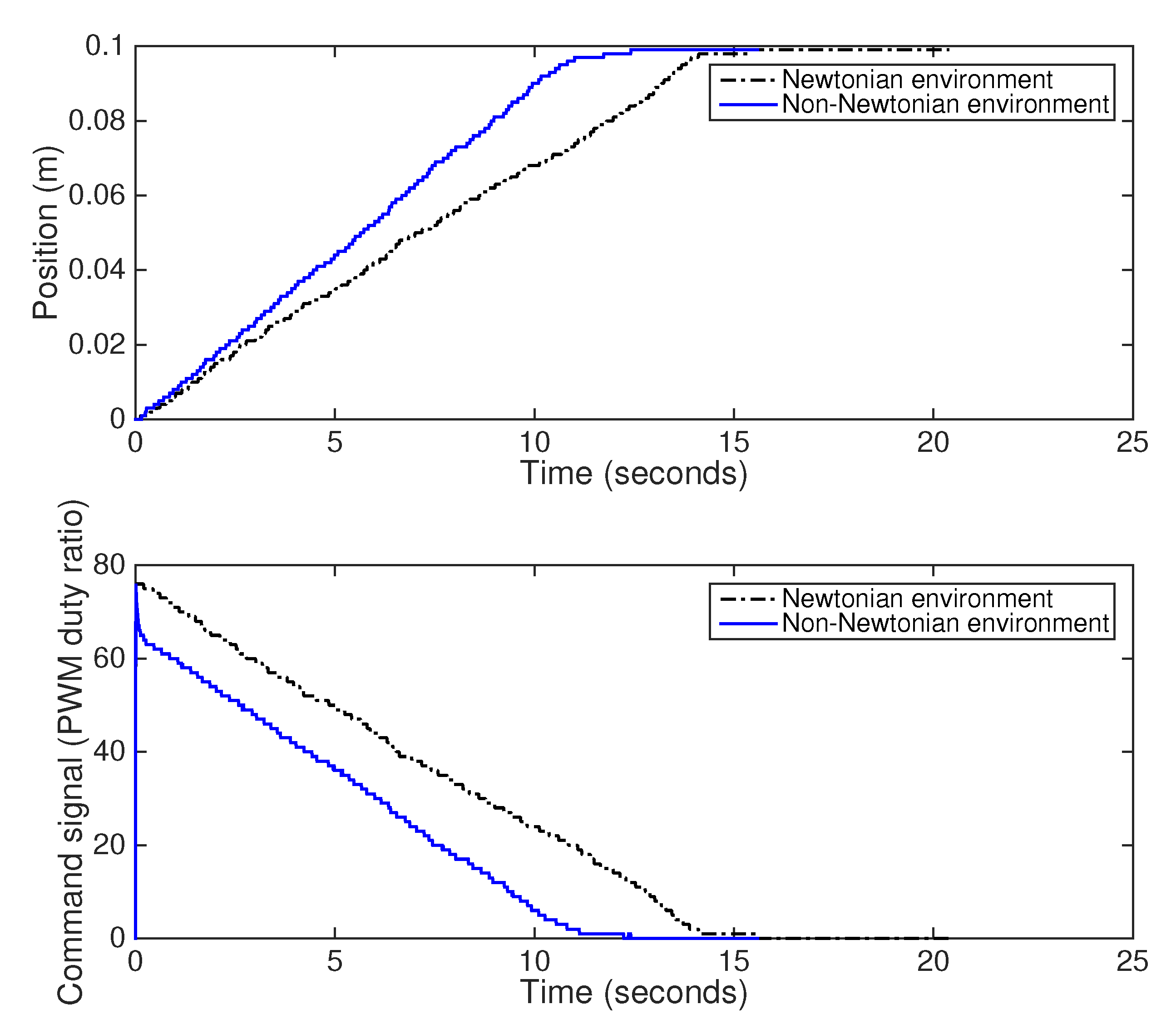
Experimental robustness tests have been performed by replacing the non-Newtonian liquid inside the cardiovascular setup with tap water. The same desired input is given to the submersible in the two operating environments, Newtonian and non-Newtonian, and the position profile for both cases is presented in Figure 8. It can be observed that the settling time for the Non-Newtonian case is 5 s faster than the tap water experiment. However, the controller proves to be robust to high environmental variations, such as the nature of the fluid, proving robustness to more than just the process’s proportional gain changes.
Disturbance rejection capabilities are also analyzed in the Newtonian framework in Figure 9. A software disturbance is also introduced at moment t = 20 s, which is successfully rejected.
The experimental tests provided in this section demonstrate that the chosen fractional order model calibrated based on analytically derived equations is accurate enough to describe the dynamics of a small scale submersible in non-Newtonian fluids.
The control strategy is designed under non-Newtonian operating conditions. Since the controllers have been tuned using the isodamping frequency domain specification, they are robust to uncertainties. Hence, the controllers also operate in other environments such as Newtonian fluids, as has been shown by the experimental data. The only limitations connected to the control strategy arise from the physical limitations of the submerged vehicle.
In terms of closed loop results, the experimental results clearly prove the efficiency and robustness of the proposed fractional order controller for accurate positioning of the submersible in non-Newtonian fluids.

6. Conclusions

The custom built experimental unit has similar non-Newtonian characteristics as the blood flow non-Newtonian process. The platform offers immense possibilities to experimentally validate non-Newtonian theories regarding modeling and control approaches.
The present study proves that non-Newtonian dynamics modeling of a submerged object can be performed by modeling its Newtonian submerged dynamics and calibrating the obtained model to fit experimental non-Newtonian setups. The obtained model is an accurate fractional order viscoelastic representation of the interaction between the submerged vehicle and its surrounding. For the obtained fractional order transfer function, a fractional order proportional derivative controller is tuned with the purpose of controlling the object’s position inside the environment. The validation of the proposed method is realized on the experimental setup by testing reference tracking performance, disturbance rejection capabilities and closed loop system robustness, both in Newtonian and non-Newtonian environments.
To conclude, it is important to emphasize that the performed experiments prove that position control can be accurately realized in a non-Newtonian environment, solidifying this statement with an accurate, experimental example.
Future developments will target both alterations of the experimental platform as well as identification and control algorithms. Scaling considerations of the model will be applied experimentally in order to reduce the dimensions of the submersible. The circulatory system will be modified in order to include bending of the tubes, and the submersible will be equipped with side propellers for steering. The non-Newtonian model will be adjusted such that it includes motion through a bent non-Newtonian environment, whereas the motion algorithm will be adapted to include steering capabilities, and a more complex control strategy will be developed.

Author Contributions

Conceptualization, C.M. and C.I.; methodology, I.B. and C.M.; software, I.B. and S.F.; validation, I.B. and S.F.; formal analysis, I.B. and C.M.; investigation, C.I.; resources, O.P.; data curation, I.B.; writing—original draft preparation, I.B.; writing—review and editing, C.M.; visualization, O.P.; supervision, C.I.; project administration, C.M.; funding acquisition, C.M. and I.B. All authors have read and agreed to the published version of the manuscript.

Funding

This work was supported by a grant of the Romanian Ministry of Education and Research, CCCDI–UEFISCDI, project number PN-III-P2-2.1-PED-2019-0322, within PNCDI III. This research was also supported by Research Foundation Flanders (FWO) under grant 1S04719N.

Institutional Review Board Statement

Not applicable.

Informed Consent Statement

Not applicable.

Conflicts of Interest

The authors declare no conflict of interest. The funders had no role in the design of the study; in the collection, analyses, or interpretation of data; in the writing of the manuscript; or in the decision to publish the results.

Appendix A. Software Development for Data Processing and Motion Control

The submersible’s microcontroller ESP8266 has been programmed to handle several tasks: acquiring data from the acceleration BNO055 IMU unit, computing the velocity and position of the vehicle with respect to the starting position, measuring environmental impedance, computing the necessary command signal for the vehicle’s motion (depending on the three operating modes: manual, auto, and emergency), and sending the position, computed command signal, and impedance measurements to the server. The robot is constantly listening for new commands sent by the server such as a new position to reach (when in auto mode), a desired PWM duty ration (when operating in manual mode), and the forced stop command (when the emergency mode is triggered).
Algorithm 1: An insight into the submersible’s software logic
Fractalfract 05 00104 i001

Appendix B. Impedance Variation in the Non-Newtonian Fluid

In order to test and validate the impedance measurement proposed solution, the DS550 sensor from Figure A1 has been attached to the surface of the submersible.
Figure A1. Impedance sensor DS550.
Fractalfract 05 00104 g0a1
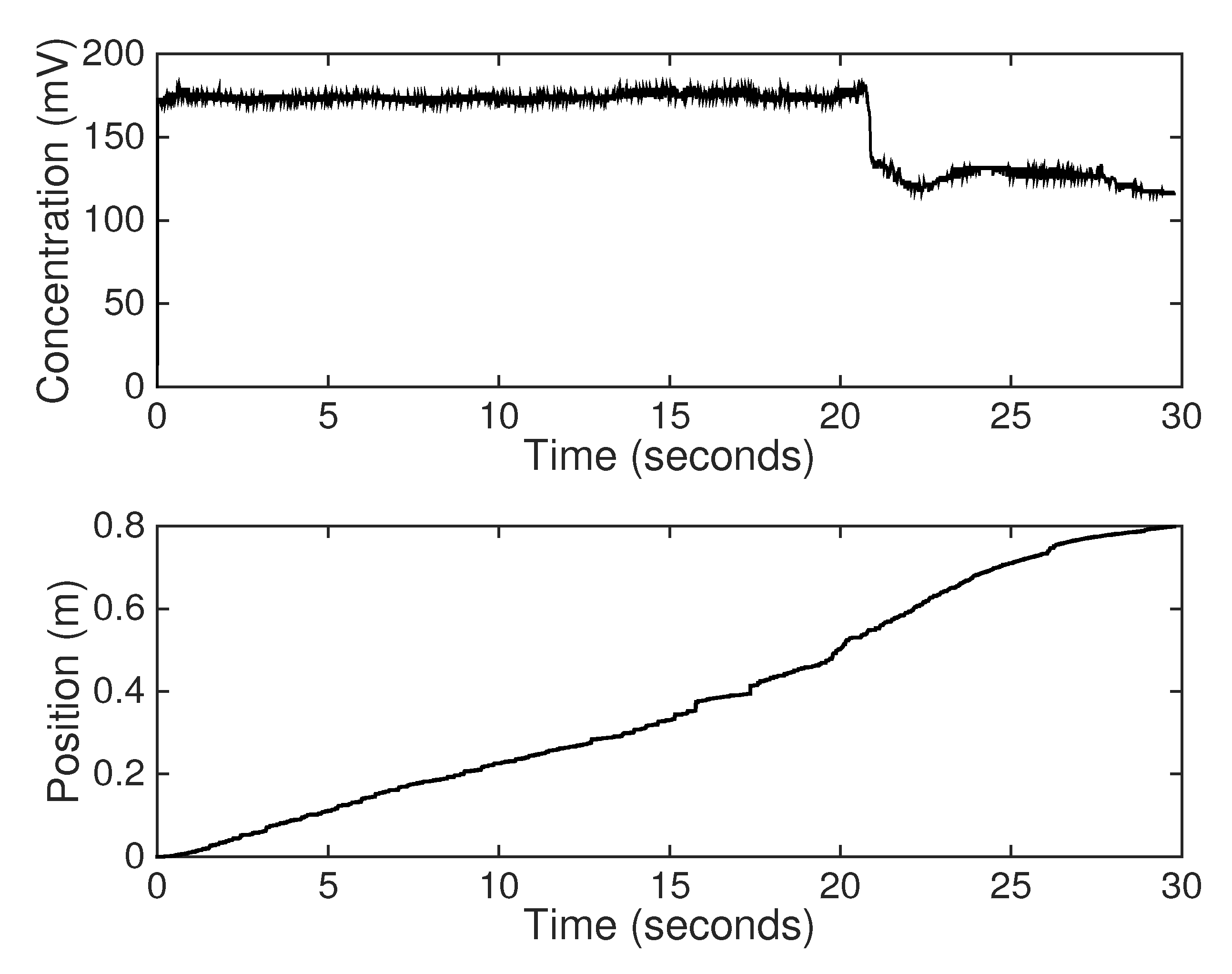
A mixture of glucose and non-Newtonian fluid has been inserted in a certain area in the tubes. The robot navigates with a constant velocity, logging data about its position and the measured impedance of the surrounding environment. Figure A2 illustrates the chemical concentration change from 175 mV, the nominal concentration, to 120 mV, where the glucose mixture has been poured.
Figure A2. Experimental test for impedance measurement for glucose insertion.
Fractalfract 05 00104 g0a2
The targeted delivery concept has been implemented only through software due to the fact that the robot is not equipped with substance administration mechanisms. The nominal operating impedance value ( 175 mV) is compared to the measured value, detecting changes that outbound the [ 20 , 20 ] mV interval. In the case of significant impedance changes, the robot is programmed to stop at the desired position until the concentration values adjust to the accepted interval. It is considered that the robot administers the proper medication while being stationed.

References

  1. Berglundand, A.; Liddle, J.A. Simultaneous positioning and orientation of a single nano-object by flow control: Theory and simulations. New J. Phys. 2011, 13, 27. [Google Scholar]
  2. Fahmy, T.M.; Fong, P.M.; Goyal, A.; Saltzman, W.M. Targeted for drug delivery. Mater. Today 2005, 8, 18–26. [Google Scholar] [CrossRef]
  3. Singh, R.; Lillard, J.W. Nanoparticle-based targeted drug delivery. Exp. Mol. Pathol. 2009, 86, 215–223. [Google Scholar] [CrossRef] [Green Version]
  4. Freeman, A.; Mayhew, E. Targeted drug delivery. Cancer 1986, 58, 573–583. [Google Scholar] [CrossRef]
  5. Li, H.; Tan, J.; Zhang, M. Dynamics Modeling and Analysis of a Swimming Microrobot for Controlled Drug Delivery. IEEE Trans. Autom. Sci. Eng. 2009, 6, 220–227. [Google Scholar]
  6. Ionescu, C.M. A memory-based model for blood viscosity. Commun. Nonlinear Sci. Numer. Simul. 2017, 45, 29–34. [Google Scholar] [CrossRef]
  7. Ionescu, C.M.; De Keyser, R. Time domain validation of a fractional order model for human respiratory system. In Proceedings of the IEEE Mediterranean Electrotechnical Conference-MELECON, Ajaccio, France, 5–7 May 2008; pp. 89–95. [Google Scholar]
  8. Ionescu, C.; Lopes, A.; Copot, D.; Machado, J.A.T.; Bates, J.H.T. The role of fractional calculus in modeling biological phenomena: A review. Commun. Nonlinear Sci. Numer. Simul. 2017, 51, 141–159. [Google Scholar] [CrossRef]
  9. Atanaga, A. Application of Fractional Calculus to Epidemiology. Fractional Dynamics. 2016. Available online: https://www.degruyter.com/document/doi/10.1515/9783110472097-011/html (accessed on 24 August 2021).
  10. Almeida, R.; Brito da Cruz, A.; Martins, N.; Monteiro, M. An epidemiological MSEIR model described by the Caputo fractional derivative. Int. J. Dyn. Control. 2019, 7, 776–784. [Google Scholar] [CrossRef] [Green Version]
  11. Al-Sulami, H.; El-Shahed, M.; Nieto, J.J.; Shammakh, W. On Fractional Order Dengue Epidemic Model. Math. Probl. Eng. 2014, 2014, 456537. [Google Scholar] [CrossRef]
  12. Pinto, C.M.; Carvalho, A.R. Fractional complex-order model for HIV infection with drug resistance during therapy. J. Vib. Control. 2016, 22, 2222–2239. [Google Scholar] [CrossRef]
  13. Birs, I.; Muresan, C.; Copot, D.; Nascu, I.; Ionescu, C. Identification for control of suspended objects in non-Newtonian fluids. Fract. Calc. Appl. Anal. 2019, 22, 1378–1394. [Google Scholar] [CrossRef]
  14. Wijngaard, R.R.; Steiner, J.F.; Kraaijenbrink, P.D.A.; Klug, C.; Adhikari, S.; Banerjee, A.; Pellicciotti, F.; van Beek, L.P.H.; Bierkens, M.F.P.; Lutz, A.F.; et al. Modeling the response of the Langtang glacier and the Hintereisferner to a changing climate since the Little Ice Age. Front. Earth Sci. 2019, 7, 143. [Google Scholar] [CrossRef]
  15. Langevin, C.D. Modeling axisymmetric flow and transport. Ground Water 2008, 46, 579–590. [Google Scholar] [CrossRef]
  16. Ye, Z.; Zhang, Y.; Wang, Y.; Huang, Z.; Song, B. Chest CT manifestations of new coronavirus disease 2019 (COVID-19): A pictorial review. Eur. Radiol. 2020, 30, 4381–4389. [Google Scholar] [CrossRef] [PubMed] [Green Version]
  17. Mason, R.J. Pathogenesis of COVID-19 from a cell biology perspective. Eur. Respir. J. 2020, 55, 2000607. [Google Scholar] [CrossRef] [PubMed] [Green Version]
  18. Gomez-Espinosa, A.; Cuan-Urquizo, E.; González-García, J. Autonomous Underwater Vehicles: Localization, Navigation, and Communication for Collaborative Missions. Appl. Sci. 2020, 10, 2020. [Google Scholar]
  19. Koutsiaris, G. A velocity profile equation for blood flow in small arterioles and venules of small mammals in vivo and an evaluation based on literature data. Clin. Hemorheol. Microcirc. 2019, 43, 321–334. [Google Scholar] [CrossRef]
  20. Womersley, J.R. An Elastic Tube Theory of Pulse Transmission and Oscillatory Flow in Mammalian Arteries; Tech. Rep. WADC-TR56-614; Wright Air Development Center: Dayton, OH, USA, 1957. [Google Scholar]
  21. Coffman, J.D.; Lempert, J.A. Venous flow velocity, venous volume and arterial blood flow. Circulation 1975, 52, 141–145. [Google Scholar] [CrossRef] [Green Version]
  22. Wynn, R.B. Autonomous Underwater Vehicles (AUVs): Their past, present and future contributions to the advancement of marine geoscience. Mar. Geol. 2004, 352, 451–468. [Google Scholar] [CrossRef] [Green Version]
  23. Birs, I.; Muresan, C.; Folea, S.; Prodan, O. An experimental nanomedical platform for controller validation on targeted drug delivery. In Proceedings of the 2017 Australian and New Zealand Control Conference (ANZCC), Gold Coast, QLD, Australia, 17–20 December 2017; pp. 161–165. [Google Scholar]
  24. Xiao, C.; Lachance, B.; Sunahara, G.; Luong, J.H.T. Assessment of Cytotoxicity Using Electric Cell-Substrate Impedance Sensing: Concentration and Time Response Function Approach Analytical. Chemistry 2002, 74, 5748–5753. [Google Scholar] [CrossRef]
  25. Ren, d.; Chui, C.O. Feasibility of Tracking Multiple Single-Cell Properties with Impedance Spectroscopy. ACS Sens. 2018, 3, 1005–1015. [Google Scholar] [CrossRef]
  26. Sene, A.; Khan, A.A.; Cox, D.; Nakamura, R.E.I.; Santeford, A.; Kim, B.M.; Sidhu, R.; Onken, M.D.; Harbour, J.W.; Hagbi-Levi, S.; et al. Impaired cholesterol efflux in senescent macrophages promotes age-related macular degeneration. Cell Metab. 2013, 17, 549–561. [Google Scholar] [CrossRef] [Green Version]
  27. Birs, I.R.; Ghita, M.; Ghita, M.; Copot, D.; Muresan, C.I.; Ionescu, C.M. An interdisciplinary, low-cost methodological framework for analysing dynamical material properties for control-related applications. IFAC Pap. 2019, 52, 159–164. [Google Scholar] [CrossRef]
  28. Siwatch, P.; Sharma, K.; Arora, A.; Tripathi, S.K. Review of supercapacitors: Materials and devices. J. Energy Storage 2019, 21, 801–825. [Google Scholar]
  29. Sidebottom, M.A.; Pitenis, A.A.; Junk, C.P.; Kasprzak, D.J.; Blackman, G.S.; Burch, H.E.; Harris, K.L.; Sawyer, W.G.; Krick, B.A. Ultralow wear Perfluoroalkoxy (PFA) and alumina composites. Wear 2016, 362, 179–185. [Google Scholar] [CrossRef] [Green Version]
  30. Tajmar, M.; Kößling, M.; Weikert, M.; Monette, M. The SpaceDrive Project—First Results on EMDrive and Mach-Effect Thrusters. In Proceedings of the Space Propulsion Conference, Seville, Spain, 14–18 May 2018. [Google Scholar]
  31. Zhao, Y.; Liu, Y.; Wen, G.; Ren, W.; Chen, G. Designing Distributed Specified-Time Consensus Protocols for Linear Multiagent Systems Over Directed Graphs. IEEE Trans. Autom. Control. 2019, 64, 2945–2952. [Google Scholar] [CrossRef]
  32. Pozo, B.G.; Garate, J.I.; Araujo, J.A.; Ferreiro, S. Energy Harvesting Technologies and Equivalent Electronic Structural Models—Review. Electronics 2018, 8, 486. [Google Scholar] [CrossRef] [Green Version]
  33. Pandikumar, A.; Rameshkumar, P. Graphene-Based Electrochemical Sensors for Biomolecules; Elsevier: Amsterdam, The Netherlands, 2017. [Google Scholar]
  34. Li, Y.; Chen, Y.Q.; Podlubny, I. Mittag—Leffler stability of fractional order nonlinear dynamic systems. Automatica 2009, 45, 1965–1969. [Google Scholar] [CrossRef]
  35. Li, Y.; Chen, Y.Q.; Podlubny, I. Stability of fractional-order nonlinear dynamic systems: Lyapunov direct method and generalized Mittag–-Leffler stability. Comput. Math. Appl. 2010, 59, 1810–1821. [Google Scholar] [CrossRef] [Green Version]
  36. Ionescu, C.M.; Kelly, J.F. Fractional calculus for respiratory mechanics: Power law impedance, viscoelasticity and tissue heterogeneity. Chaos Solitons Fractals 2017, 102, 433–440. [Google Scholar] [CrossRef]
  37. Silvatti, A.P.; Cerveri, P.; Telles, T.; Dias, F.A.S.; Baroni, G.; Barros, R.M.O. Quantitative underwater 3D motion analysis using submerged video cameras: Accuracy analysis and trajectory reconstruction. Comput. Methods Biomech. Biomed. Eng. 2002, 16, 1240–1248. [Google Scholar] [CrossRef] [Green Version]
  38. Dilen, D.R. The motion of floating and submerged objects in the Chattahoochee River, Atlanta, GA. J. Forensic Sci. 1984, 29, 1027–1037. [Google Scholar] [CrossRef]
  39. Jones, D.A.; Clarke, D.B.; Brayshaw, I.B.; Barillon, J.L.; Anderson, B. The Calculation of Hydrodynamic Coefficients for Underwater Vehicles. 2002. Available online: https://citeseerx.ist.psu.edu/viewdoc/download?doi=10.1.1.589.9638&rep=rep1&type=pdf (accessed on 24 August 2021).
  40. Bachmeyer, R.; Whitcomb, L.L.; Grosenbaugh, M.A. An accurate four quadrant nonlinear dynamical model for marine thrusters: Theory and experimental validation. IEEE J. Ocean. Eng. 2000, 25, 146–158. [Google Scholar] [CrossRef]
  41. Le Page, Y.G. Hydrodynamics and Control of an Autonomous Underwater Vehicle Equipped with a Vectored Thruster; Florida Atlantic University: Boca Raton, FL, USA, 2000. [Google Scholar]
  42. Fossen, T.I. Marine Control Systems Guidance, Navigation, and Control of Ships, Rigs and Underwater Vehicles; Marine Cybernetics: Trondheim, Norway, 2002. [Google Scholar]
  43. Carlton, J.S. Marine Propellers and Propulsion; Butterworth-Heinemann: Oxford, UK, 1994; pp. 95–115. [Google Scholar]
  44. Birs, I.; Muresan, C.; Prodan, O.; Folea, S.; Ionescu, C.M. Analytical modeling and preliminary fractional order velocity control of a small scale submersible. In Proceedings of the 2018 SICE International Symposium on Control Systems (SICE ISCS), Tokyo, Japan, 9–11 March 2018; pp. 157–162. [Google Scholar]
  45. Snyman, J.A. An Introduction to Basic Optimization Theory and Classical and New Gradient-Based Algorithms; Practical Mathematical Optimization; Springer: Berlin/Heidelberg, Germany, 2005. [Google Scholar]
  46. Pardalos, P.M.; Resende, M.G.C. Handbook of Applied Optimization; Oxford University Press: Oxford, UK, 2002. [Google Scholar]
  47. Watanabe, T.; Yoshikawa, T. Grasping Optimization Using a Required External Force Set. IEEE Trans. Autom. Sci. Eng. 2007, 4, 52–66. [Google Scholar] [CrossRef]
  48. Vilanova, R.; Visioli, A. PID Control in the Third Millennium; Springer: London, UK, 2012. [Google Scholar]
  49. Machado, J.A.T.; Galhao, A.M.S.F.; Trujillo, J.J. On development of fractional calculus during the last fifty years. Scientometrics 2014, 98, 577–582. [Google Scholar] [CrossRef] [Green Version]
  50. Jifeng, W.; Yuankai, L. Frequency domain analysis and applications for fractional-order control systems. J. Phys. Conf. Ser. 2005, 13, 268. [Google Scholar] [CrossRef]
  51. Magin, R.; Vinagre, B.; Podlubny, I. Can Cybernetics and Fractional Calculus Be Partners? Searching for New Ways to Solve Complex Problems. IEEE Syst. Man Cybern. Mag. 2018, 4, 23–28. [Google Scholar] [CrossRef]
  52. Liu, H.; Pan, Y.; Li, S.; Chen, Y. Adaptive Fuzzy Backstepping Control of Fractional-Order Nonlinear Systems. IEEE Trans. Syst. Man Cybern. Syst. 2017, 47, 2209–2217. [Google Scholar] [CrossRef]
  53. Bugliarello, G.; Sevilla, J. Velocity distribution and other characteristics of steady and pulsatile blood flow in fine glass tubes. Biorheology 1970, 7, 85–107. [Google Scholar] [CrossRef]
  54. Srivastava, N. Analysis of Flow Characteristics of the Blood Flowing through an Inclined Tapered Porous Artery with Mild Stenosis under the Influence of an Inclined Magnetic Field. J. Biophys. 2014, 2014. [Google Scholar] [CrossRef]
  55. Beschi, M.; Padula, F.; Visioli, A. The generalised isodamping approach for robust fractional PID controllers design. Int. J. Control. 2015, 90, 1157–1164. [Google Scholar] [CrossRef]
  56. Muresan, C.; Birs, I.; Ionescu, C.; De Keyser, R. Tuning of fractional order proportional integral/proportional derivative controllers based on existence conditions. Proc. Inst. Mech. Eng. Part I J. Syst. Control. Eng. 2018, 233, 384–391. [Google Scholar] [CrossRef]
  57. Oustaloup, A.; Levron, F.; Mathieu, B.; Nanot, F.M. Frequency-Band Complex Noninteger Differentiator: Characterization and Synthesis. IEEE Trans. Circuits Syst.-Fundam. Theory Appl. 2020, 2020, 25–39. [Google Scholar] [CrossRef]
  58. Tricaud, C.; Chen, Y.Q. An approximate method for numerically solving fractional order optimal control problems of general form. Comput. Math. Appl. 2010, 59, 1644–1655. [Google Scholar] [CrossRef] [Green Version]
  59. De Keyser, R.; Muresan, C.I.; Ionescu, C. An efficient algorithm for low-order direct discrete-time implementation of fractional order transfer functions. ISA Trans. 2018, 74, 229–238. [Google Scholar] [CrossRef]
  60. Blevins, R.D. Formulas for Natural Frequency and Mode Shape; Kreiger Publishing: Malabar, FL, USA, 1979. [Google Scholar]
  61. Wu, W.T.; Massoudi, M. Recent Advances in Mechanics of Non-Newtonian Fluids; MDPI: Basel, Switzerland, 2020. [Google Scholar]
Figure 1. Experimental setup that resembles the cardiovascular system.
Fractalfract 05 00104 g001
Figure 2. Custom built autonomous submersible robot.
Fractalfract 05 00104 g002
Figure 3. Incorporated electronics inside the submersible.
Fractalfract 05 00104 g003
Figure 4. Free body diagram of a submersible.
Fractalfract 05 00104 g004
Figure 5. Position experimental data compared to the identified positioning model for the non-Newtonian environment.
Fractalfract 05 00104 g005
Figure 6. Bode diagram of the open loop system with the fractional order PD controller.
Fractalfract 05 00104 g006
Figure 7. Fractional order PD controller experimental validation in the non-Newtonian environment.
Fractalfract 05 00104 g007
Figure 8. Fractional order PD controller experimental robustness validation in Newtonian and non-Newtonian operating conditions.
Fractalfract 05 00104 g008
Figure 9. Fractional order PD controller experimental validation in a Newtonian environment.
Fractalfract 05 00104 g009
Table 1. Analytic Newtonian motion design parameters.
ParameterValue
C t 0.3
C d 0.6
d0.04 m
r0.02 m
A0.0013 m 2
ρ 1060 kg/m 3
A f 0.031 m 2
β 0.2473
V0.1 m/s
m0.1 kg
u 0 1 m/s
Publisher’s Note: MDPI stays neutral with regard to jurisdictional claims in published maps and institutional affiliations.