1. Introduction
In large network architectures, the dynamic host configuration protocol (DHCP) service plays a strategic role. However, the redundancy of the DHCP system must be improved to prevent interruptions in the DHCP service that result from single point failures. The main objective of applying the DHCP failover (DHCP-F) to multiple servers is to maintain a consistent view (DHCP scope) of assigned addresses across the servers to avoid the double allocation of an IP address.
In the request for comments (RFC) specification 2131, the DHCP [
1] is defined as a mechanism that allows network devices to automatically obtain a unique IP address and other configuration information that is necessary for communication on an IP network. Since it has become the most popular approach to distributing IP addresses to internet users, the use of the DHCP has increased linearly at an annual rate of almost 5%, as described by the International Telecommunications Union (ITU) studies [
2]. The DHCP-F [
3,
4] is an extension of the dynamic host configuration protocol. It was created as an RFC draft, and it remains the most used in different software implementations of the DHCP that allow the failover mechanism.
This paper describes the architecture and algorithms that are needed to scale out the DHCP-F over a virtual private network (VPN) or other kinds of large-scale private communications over the internet, as most enterprises and university campuses have one or more links that connect a local network to the Internet.
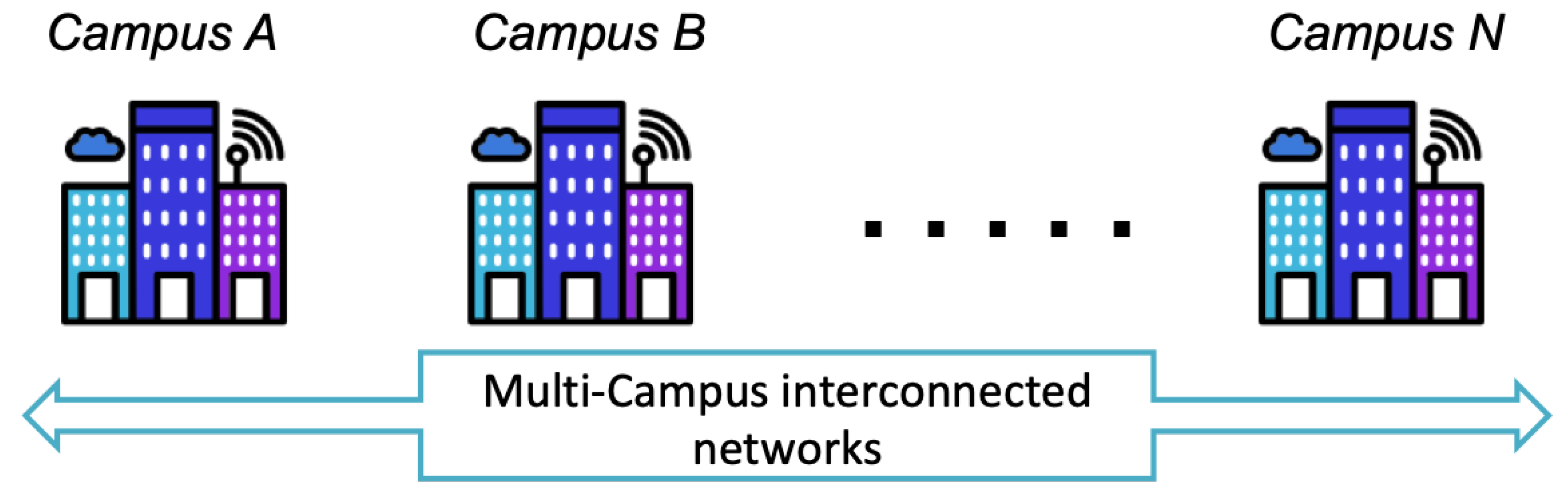
Figure 1 shows a simple overview of a scenario in which the proposed solution is applied to manage DHCP failovers over multiple smart cities or campuses that are VPN connected.
In this scenario, links with high redundancy are widely deployed to avoid a loss of internet connection. In order to create a large DHCP scope, structures such as virtual local area networks (VLANs) are distributed over VPNs, and the redundancy mechanism of the DHCP-F specification is limited to just two servers.
The limited redundancy and scalability of the DHCP-F have become problematic due to the extension of private networks worldwide (enabled by VLANs and VPNs) using the internet. Similarly, there are concerns about physical network infrastructure, especially those that are not under enterprise domains. This situation can generate conflicts with addresses, especially when using network equipment that attaches the IP to security polices, such as access control lists [
5], firewalls, and VPN appliances. The presented study does not consider issues related to clock synchronization between failover servers, as detailed by Umeno and Lynch [
6]. A timed I/O automaton formal verification [
7] of the DHCP-F was presented by Fan and Droms [
8], who considered managing the DHCP-F with two algorithms: the leader election algorithm and the lease algorithm. The former was verified for a set of server candidates. There is justification for further investigation when the set of server candidates are organized as a hierarchical structure, such as the VLAN and VPN networks mapped with the logic of the DHCP-F system. The proposed solution is not generalized (as was the case for Fan and Droms [
8]) for any number of failover servers; instead, it is restricted to a pre-ordered number of failover servers from a real case of multiple campus networks which are geographically separated but interconnected with the same IP assignment logic. The challenge in this case is the reuse of the DHCP-F in each network and the relay of the failover server logic to the different campus networks. On the basis of the hierarchical logic of DHCP-F architecture, the proposed solution is named the DHCP hierarchical failover (DHCP-HF). Therefore, it is based on the RFC 2131 specification and related system assumptions. The hierarchical structure is retained, but more than two members are included as failover servers by using a new simple algorithm for the bind update (BNDUPD) process. The system assumptions for the DHCP, DHCP-F, and DHCP-HF can be summarized as:
Safety and liveness properties depend on the correct behavior of the network and environment. Both safety and liveness depend on the clock assumption.
This paper is organized as follows. The next section describes the main features of the DHCP-F protocol.
Section 3 presents the DHCP hierarchical failover (DHCP-HF) mechanism and the relative Extended Update algorithm. Then, in
Section 4, the simulation results are discussed, followed by conclusions.
2. DHCP-F Mechanism and Protocol: Fundamental Concepts
The DHCP-F protocol specification, as defined in RFC 2131, is designed for the dual relationship between a primary and a secondary server. It manages these two members only. The failover server receives all DHCP messages from clients and relay agents. From lease binding messages, the DHCP failover server obtains the addresses assigned from either the local configuration or from an external DHCP server.
The primary and failover servers exchange heartbeat and lease binding messages in order to detect any failures and track recent updates regarding lease transactions. Lease binding update messages reduce the risk of assigning duplicate addresses during the failover detection time and failover initiation time.
The main failover server states in the DHCP-F and DHCP-HF are:
Normal: the main and peer failover servers can communicate with each other in this state. The main server is responsible for responding to client requests.
Communication-interrupted: when communication between two servers is interrupted, the server will automatically switch to this state. In this state, both the main and failover server are responsible for client requests, but they allocate IP addresses to clients from two different pools.
Partner-down: when a server is in the communication-interrupted state, if it receives an outside command or the safe-time expires, the state will transition to partner-down. In this state, the server assumes that the other server is down and will respond to client requests alone, including IP address assignment, lease renewal, and so on.
Recover-wait: the server has received a complete update from its peer and is waiting for the maximum client lead time (MCLT) period to elapse before transitioning to the recover-done state.
Recover-done: the server has completed an update from its peer.
Shutdown: this state allows one peer to inform the other peer that it is going out of service for a long period of time so that the other peer can immediately transition to the partner-down state and completely assume control of the DHCP service.
2.1. The Lazy Update Process
To improve the responsiveness of the DHCP service when configured to operate with a failover server, the DHCP server does not acknowledge the assignment of a lease to a client, but the lease records are exchanged between the failover servers by the lazy update process. This process is intended to maintain DHCP server performance by reducing the number of messages required by the client to get a new dynamic host configuration (DHC).
2.2. The Maximum Client Lead Time
When a failure event occurs after a primary has acknowledged a lease to a client but prior to it updating its failover server, the failover server requires an estimate of the upper-bound lease time employed. For that, a parameter called the maximum client lead time, or MCLT, is adopted by the primary server to notify the failover server during failover server initialization about the time leased before the failure.
2.3. The Hierarchical System
The hierarchical system is based on the DHCP-F protocol, a solution defined by Droms in RFC 2131. The proposed DHCP-HF approach extends the hierarchical relationship between two members—primary and secondary—to a set of hierarchical DHCP failover servers. In the proposed architecture, failover servers are deployed in a hierarchical order, meaning that there is just one primary server, one secondary server, one tertiary server, and so on.
2.4. The Load Balance
The load balance specification defined in the DHCP-F [
3] proposes splitting the number of addresses of the DHCP scope into two address subparts by using the split command or the hba command [
9]. The load balance is done using the C language implementation of the algorithm known as “Pearson’s hash” [
10]. RFC 3074 [
9] defines the DHC load balance procedures. According to
Section 3, there are no security guarantees provided for the implementation of the balancing algorithm (security guarantees prevent tampering attacks during communication between DHCP servers). For this reason, this study does not cover the functionalities of load balance. This security topic will be investigated in future works.
3. DHCP-HF Mechanism over the Extended Hierarchical System
The proposed architecture introduces an extended hierarchical system to allow more than two DHCP failover servers to work together without changing the original dual relation, which has been defined and implemented since the beginning of the DHCP-F specification.
The dual relation will be scaled over a chain of hierarchical failover servers, and the hierarchical preconfigured order will improve the responsiveness of the DHCP service.
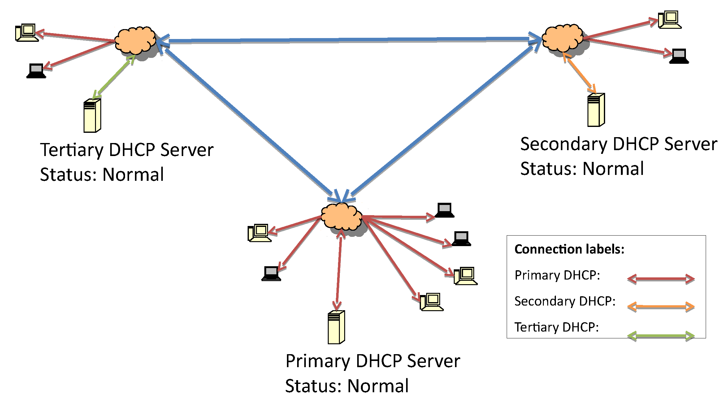
In order to evaluate the proposed failover mechanism, an architecture with one primary, one secondary, and one tertiary server in the hierarchy is considered. They are respectively distributed over three interconnected local networks, as depicted in
Figure 2.
It is assumed that the list of IP addresses of the failover server is known by all of the servers. The system’s working state before the failure is represented in
Figure 2. All servers are working, and the primary is the responsive server.
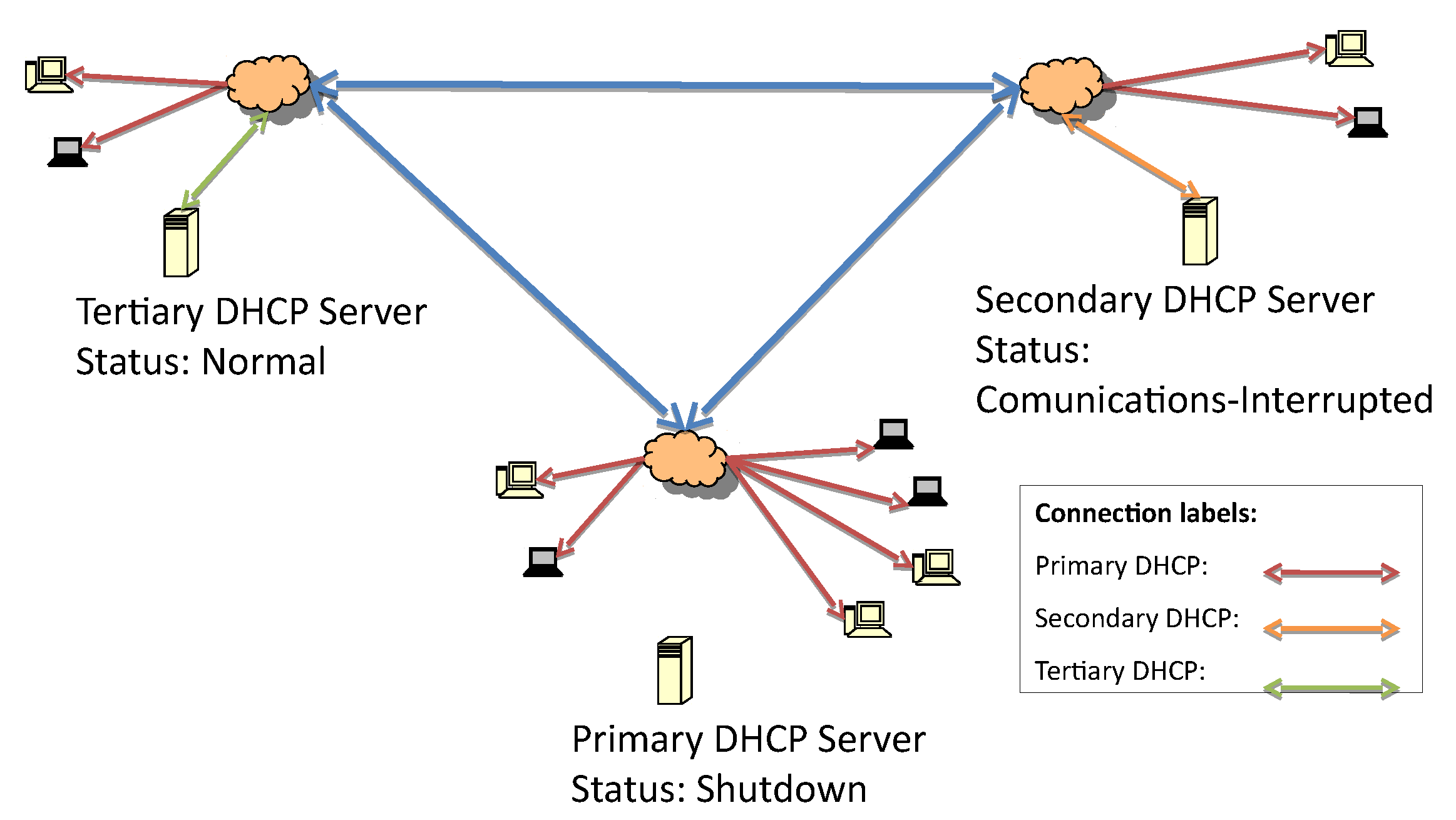
Figure 3 represents the first fault, which is caused by losing connectivity to the primary DHCP server. The detection of the lost connection triggers the secondary server to initiate failover procedures and act as the responsive server.
At the beginning of the secondary server’s responsive server role, it is possible that some hosts have retained the same address while the lease time is still valid. When the lease time expires, the next requests will be answered by the secondary server.
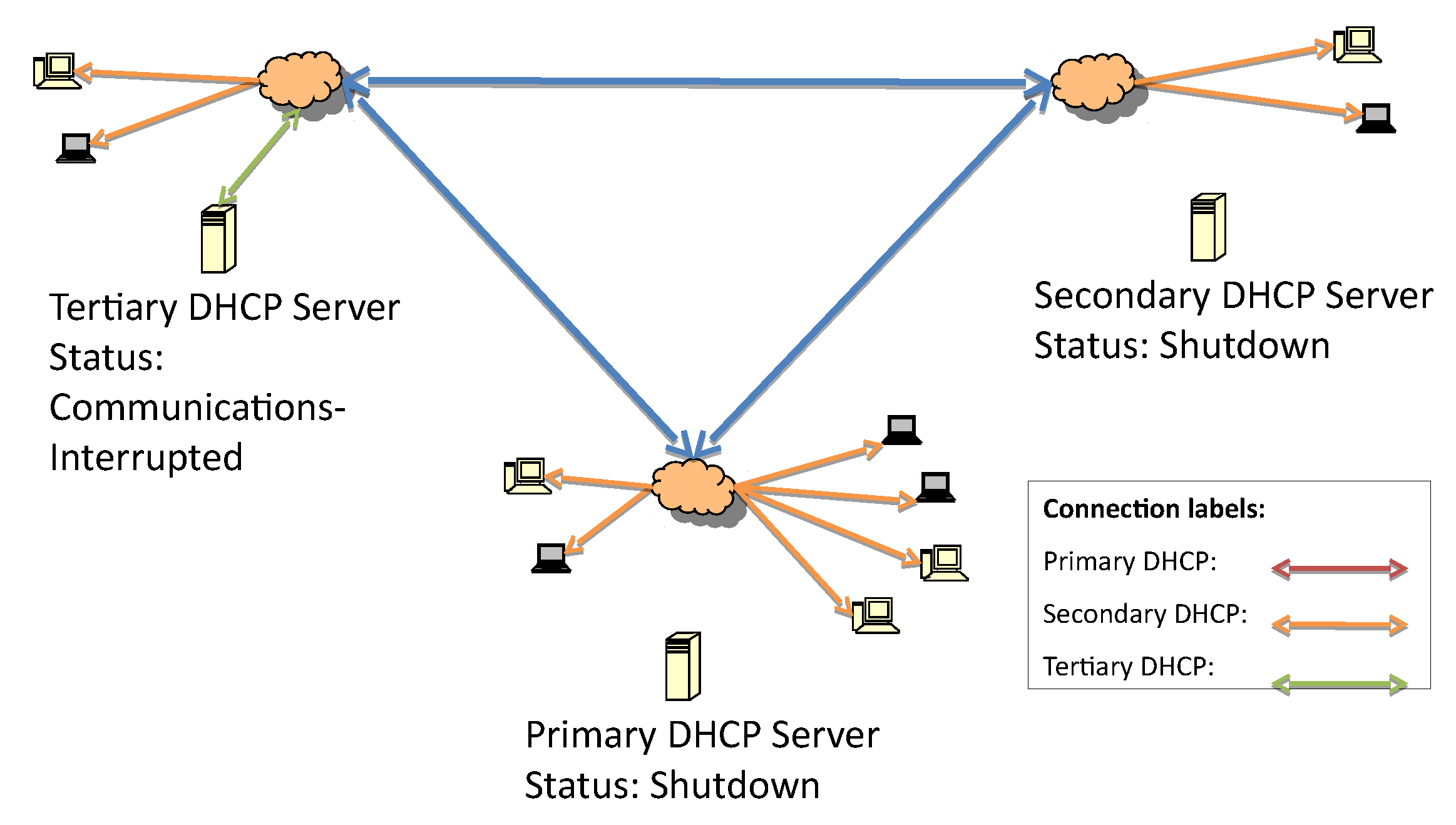
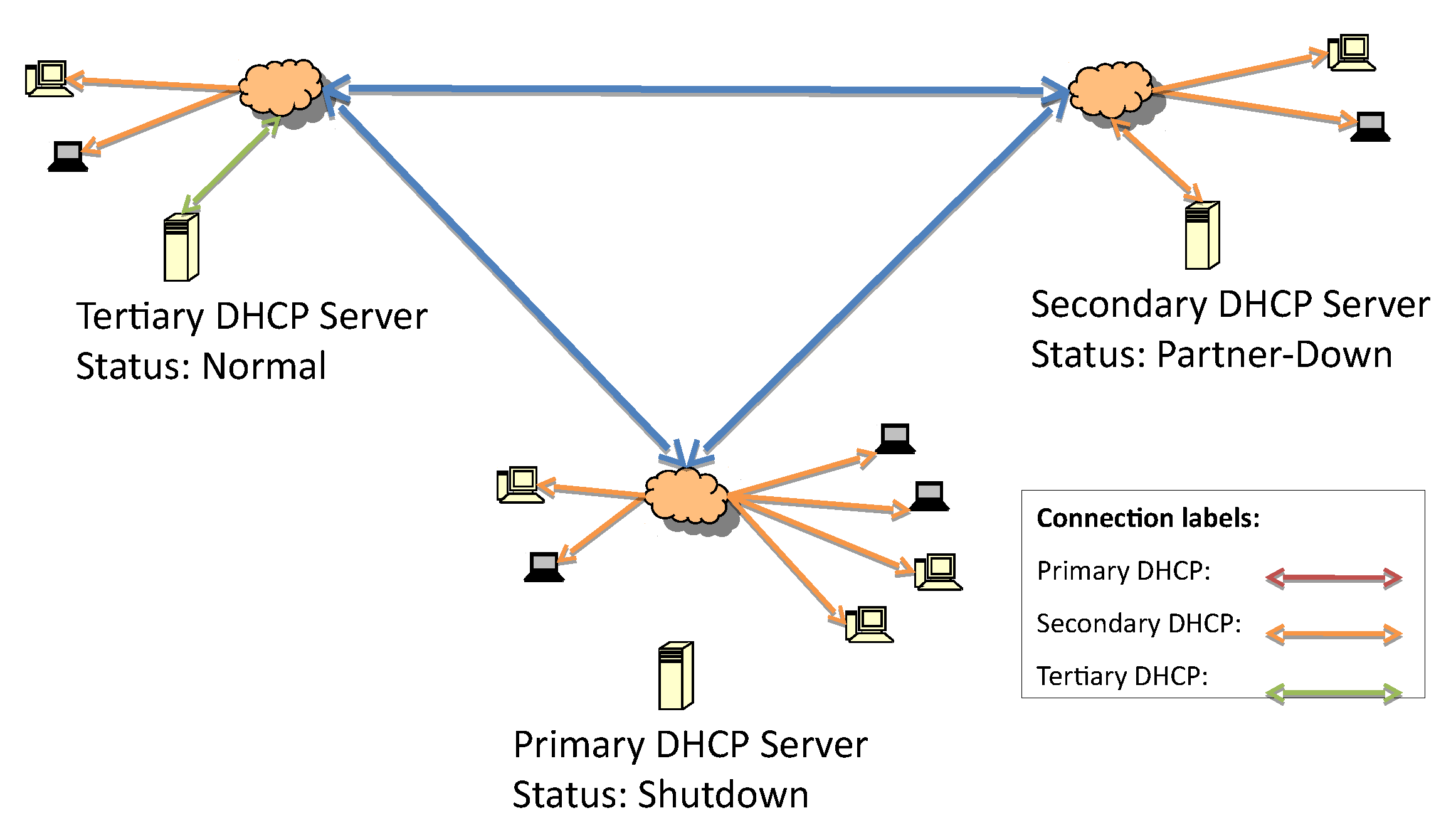
Figure 4 presents the second fault due to the loss of communication with the secondary DHCP.
Once the connection between the primary and secondary server is lost, as in
Figure 4, the tertiary server initiates the failover service verification routine. Since the IP address list of the failover servers in the hierarchy is known, the tertiary server can start to check whether one of them is up and responsive. If there are no responsive servers, this tertiary server will start to respond to DHCP discover and request messages.
In
Figure 5, the DHCP messages in green represent the tertiary server delivering IP addresses to all subnetworks once it determines that neither of the higher-priority servers are up.
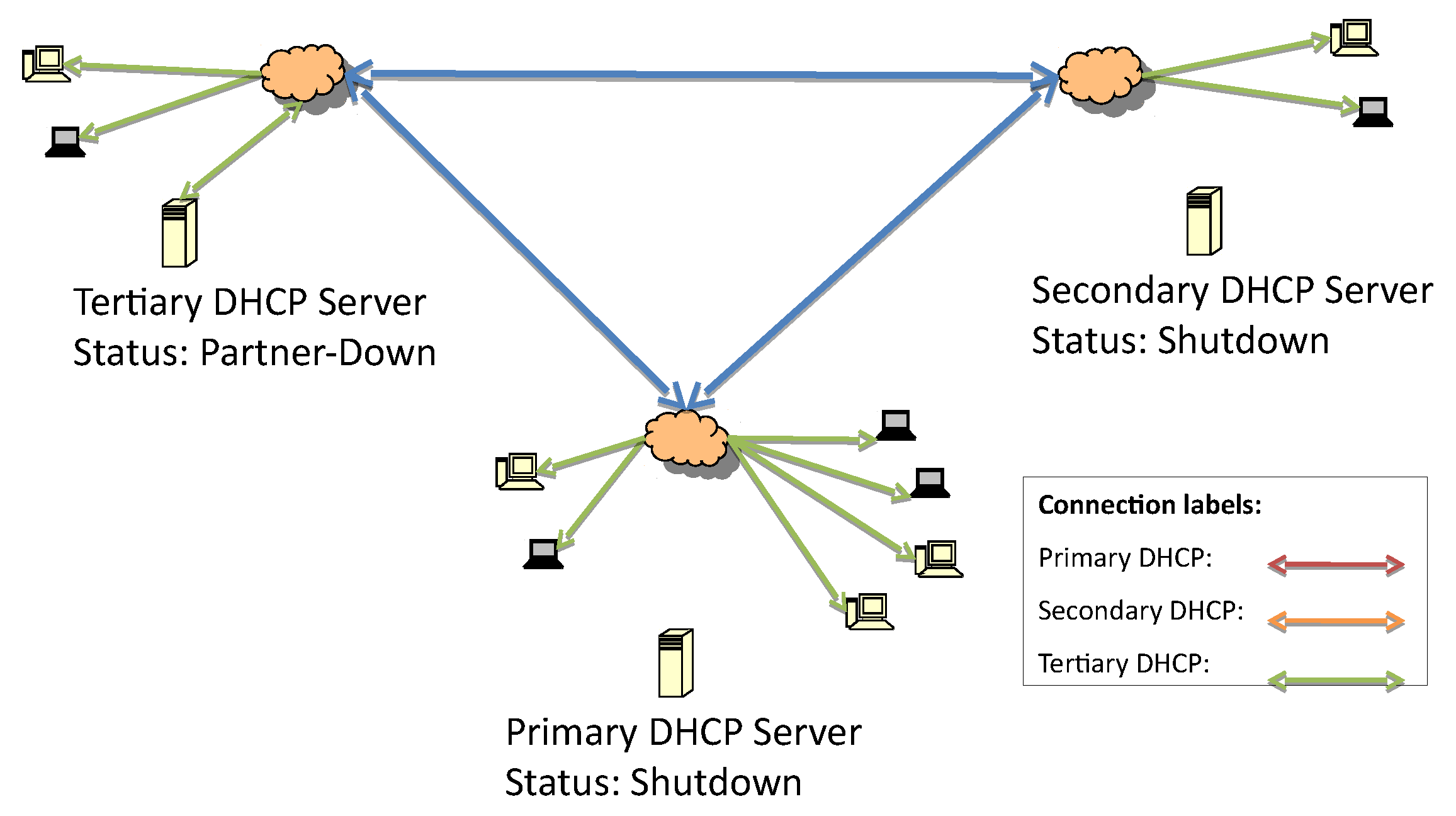
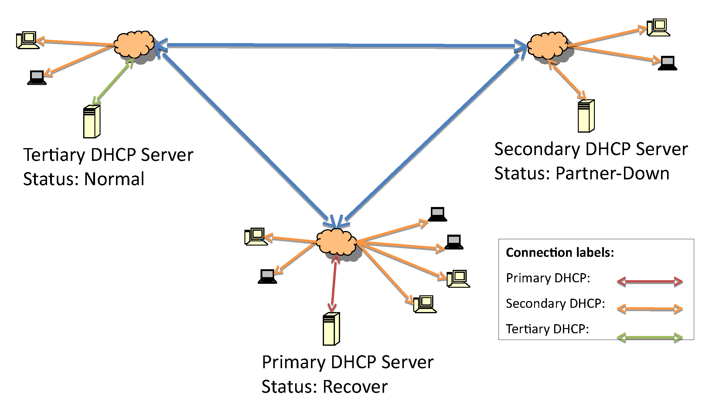
The recovery process, outlined in
Figure 6, starts from the same principle that is defined in the DHCP-F specification. When the secondary server comes back online, it should start service without replying to any requests since there is already one server allocating IP addresses.
In this case, the responsive server is the one immediately below it on the hierarchical list, so the secondary server will be the next responsive server, as illustrated in
Figure 6.
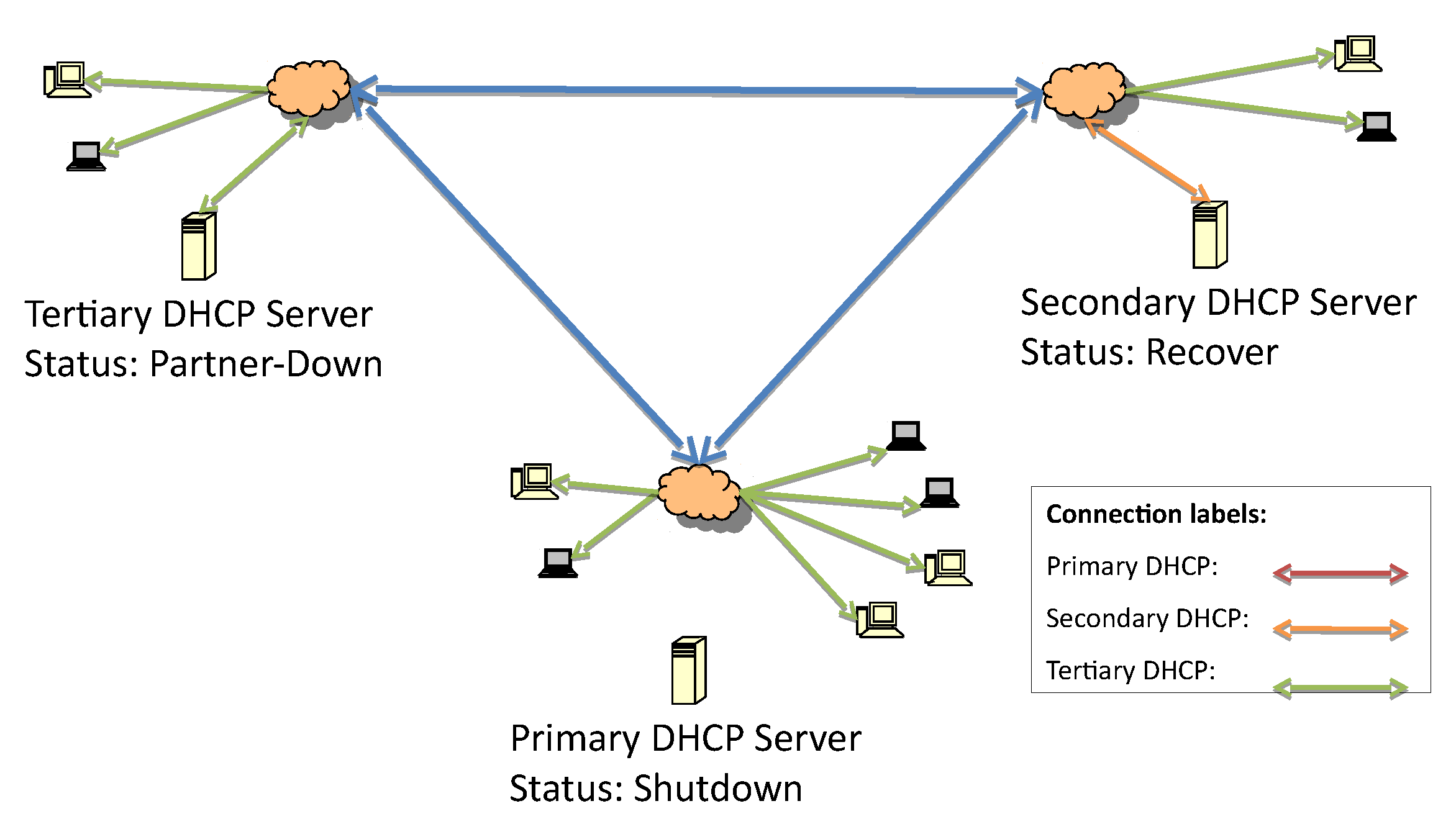
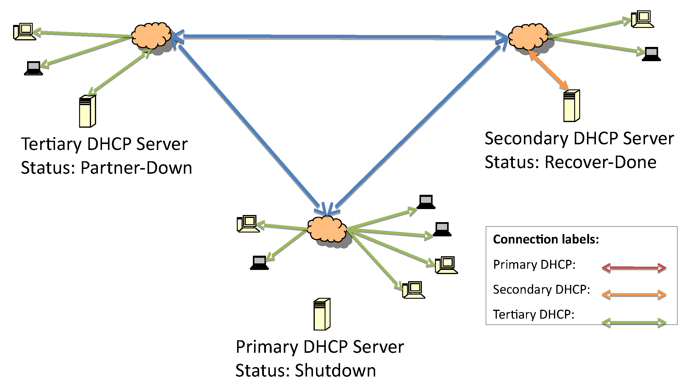
Figure 7 represents the change from the shutdown state to the recover state when the update of the lease file begins.
After the lease file has been completely updated, the secondary server status moves from recover to recover-done, as seen in
Figure 6 and
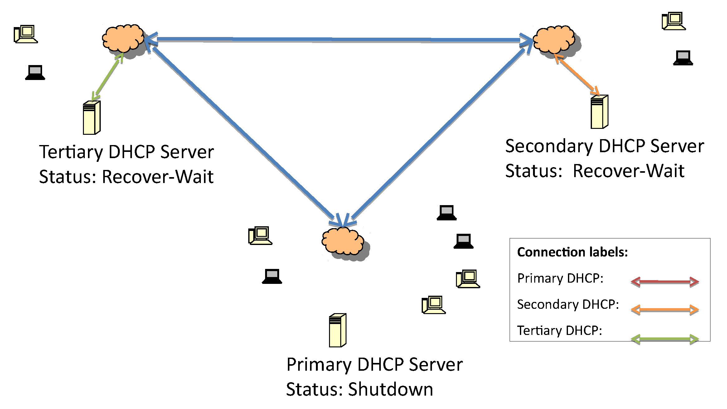
Figure 7. The recover-done state means that the server is fully updated and can assume the responsive role. Once the lease file is fully updated, both servers change their statuses to recover-wait—an unresponsive state—and they wait for the maximum client lead time (MCLT) to change their statuses. Then, the secondary server starts to reply to DHCP requests (
Figure 8 and
Figure 9).
This waiting time is important to avoid synchronization problems between the DHCP servers; after that time, the higher-priority DHCP server is set to responsive.
Every time a non-primary server recovers and becomes responsive, its state is partner-down. Even if the predecessor state is not shutdown or paused, it should recover before switching itself to responsive. In
Figure 10, the system is working with the secondary server acting as responsive. The primary server network link turns on, and it is in the recover state while waiting for updates.
Although the system behaves as a multiple-server system, in practice, it works solely through dual relationships: in other words, a server can be activated, but as a lower-priority server exists in the hierarchy, it is in the non-responsive state.
If interference stops a server that is not a direct part of the dual relationship, there is no direct action taken in the proposed model. That is, the server does not change from responsive to unresponsive if any agent is not satisfied. However, the recovery process differs from the server failover process (when the server’s highest degree assumes the lowest-level functions). This is because the intention of the scheme is to ensure that the service is working, not that the highest-degree server is always the one to deliver IP addresses.
This occurs because there are update packages which are always being sent by the server that is delivering the data; these packages form a unicast for all reported instances. Additionally, the system is monitored. So, there is always knowledge of which server is the master at that time.
The purpose of the BNDUPD package—the standard set for updating the loan file in the failover protocol—is to update the files in the hierarchical system. The difference here is that it is no longer restricted to a single server.
Upon receiving the update from the server, responsive servers that are not in responsive mode should return a BNDACK message as soon as they are updated.
3.1. Responsive Server Conditions
When discussing the DHCP, the term “responsive” refers to the server that is in charge of replying to DHCP requests. For a server to become responsive, it has to meet one of the following conditions:
It is a primary server and is updated.
It is not primary, but it has ensured that the status has been changed to paused or shutdown in a responsive server that is higher in the higher hierarchical order (primary grades), and that there is no server positioned between itself and the server whose status has changed (entered into a shutdown state or whose system failed), that can distribute IP addresses.
It is not primary, but it cannot connect to any server with a higher priority.
The partner-down or communication-interrupted states always occur relative to the status of the server immediately above, e.g., the fourth modifies its state due to the state of the third, the third modifies its state due to the state of the second, etc.
This is consistent with the definition of the same states defined in the protocol. However, the determination of whether a server is responsive is not only a result of its state but also the presence and state of others that are monitoring it; these others are related to the higher hierarchical order and are triggered solely when a low-grade server is on the verge of becoming responsive due to the state of its partner.
This process is the simplest development to be made, since monitoring can be done from the different instances of servers, exactly as the original system advances the control of inconsistencies.
3.2. DHCP-HF Failover Hierarchical Algorithm
The algorithm assumes that the proposed failover mechanism applies to n hierarchical servers. The responsive server updates all low-priority servers, as described in Algorithm 1. The relation between the time update, lease expiration, and potential expiration persist as is, and the updates work through a dual process between each low-priority non-responsive server and the responsive server.
| Algorithm 1 Dynamic host configuration protocol hierarchical failover (DHCP-HF) extended update |
- 1:
procedureUpdate() - 2:
for all do - 3:
Start - 4:
Start - 5:
while and do - 6:
Send - 7:
Start - 8:
while and do - 9:
Receive - 10:
end while - 11:
end while - 12:
end for - 13:
end procedure
|
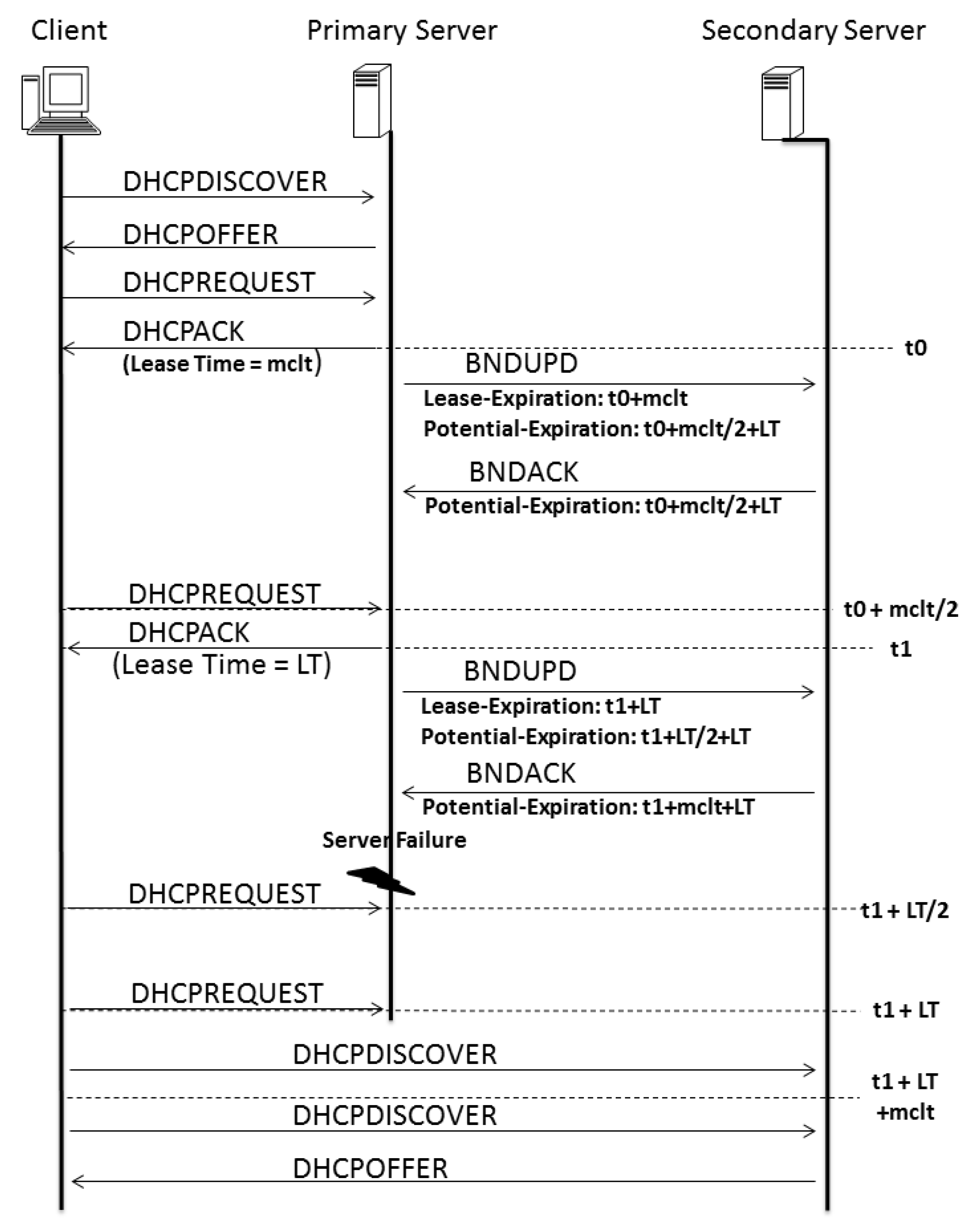
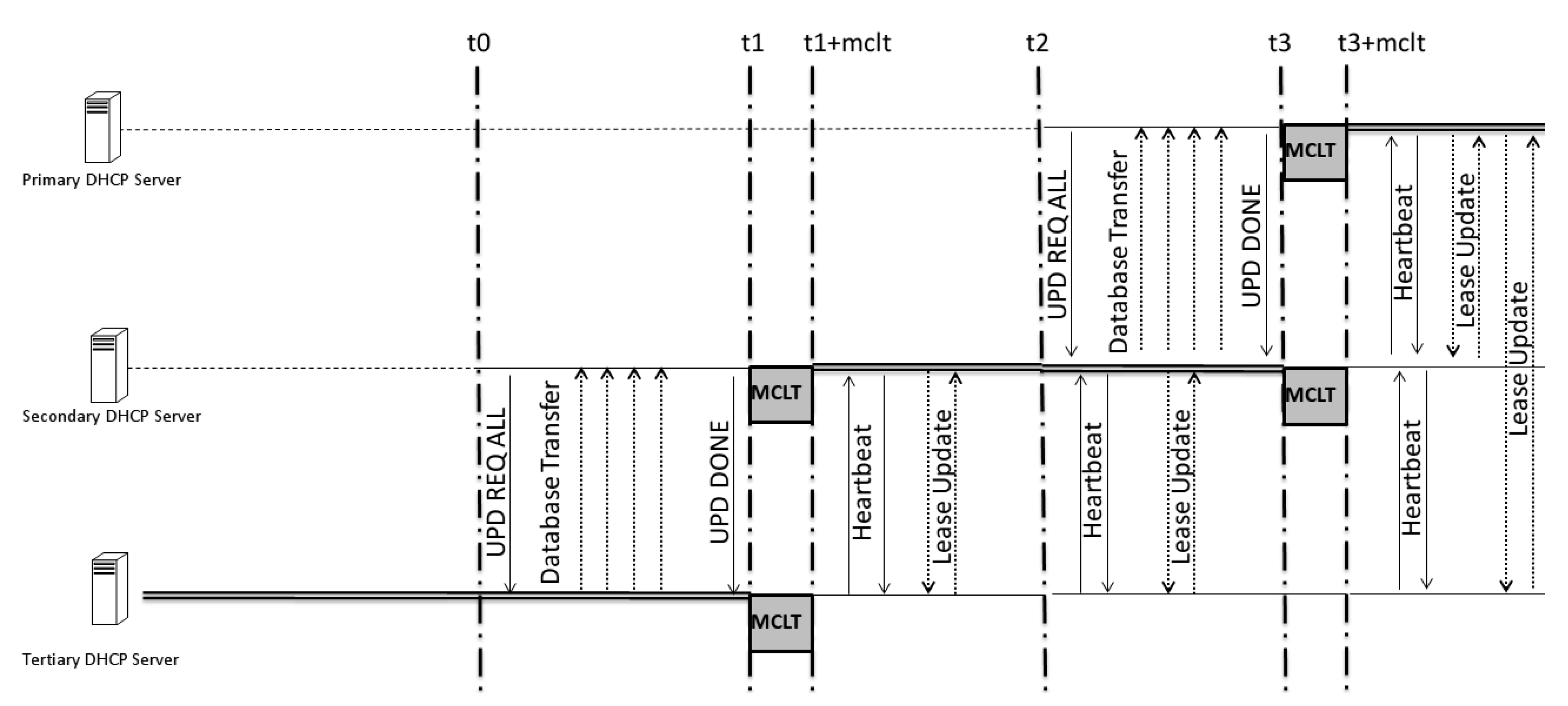
The difference between the proposed system and the DHCP-F is related to time. In a model proposed in 2003 [
3], the time behavior of both servers was described as depicted in
Figure 11. The time between both servers to update themselves is based on two variables: MCLT and lease time (LT). The difference between these times has to be different for all of the low-priority servers.
On the basis of the proposed model and Algorithm 1, we can estimate (by Equation (
1)) an upper-bound delay for the potential expiration time required before a secondary failover server becomes the new responsive server in the worst failure case, as pictured in
Figure 11.
to
where
is the failure detection time and
h is the number of hops between the responsive server and the one of interest. For example, if the responsive server is the primary server, and it is updating the tertiary, the potential expiration is
This number allows for the same time delay between the responsive server and the consecutive one, but the others will have a gap that is twofold in the MCLT; this is important for facilitating a conflict-free transition between servers, as the occurrence of just one MCLT between them could be dangerous since the knowledge of time between the last update is not fixed, as described in Algorithm 1, which shows that the BNDUPD message can be delivered with a time that differs from that of client–server acknowledgment.
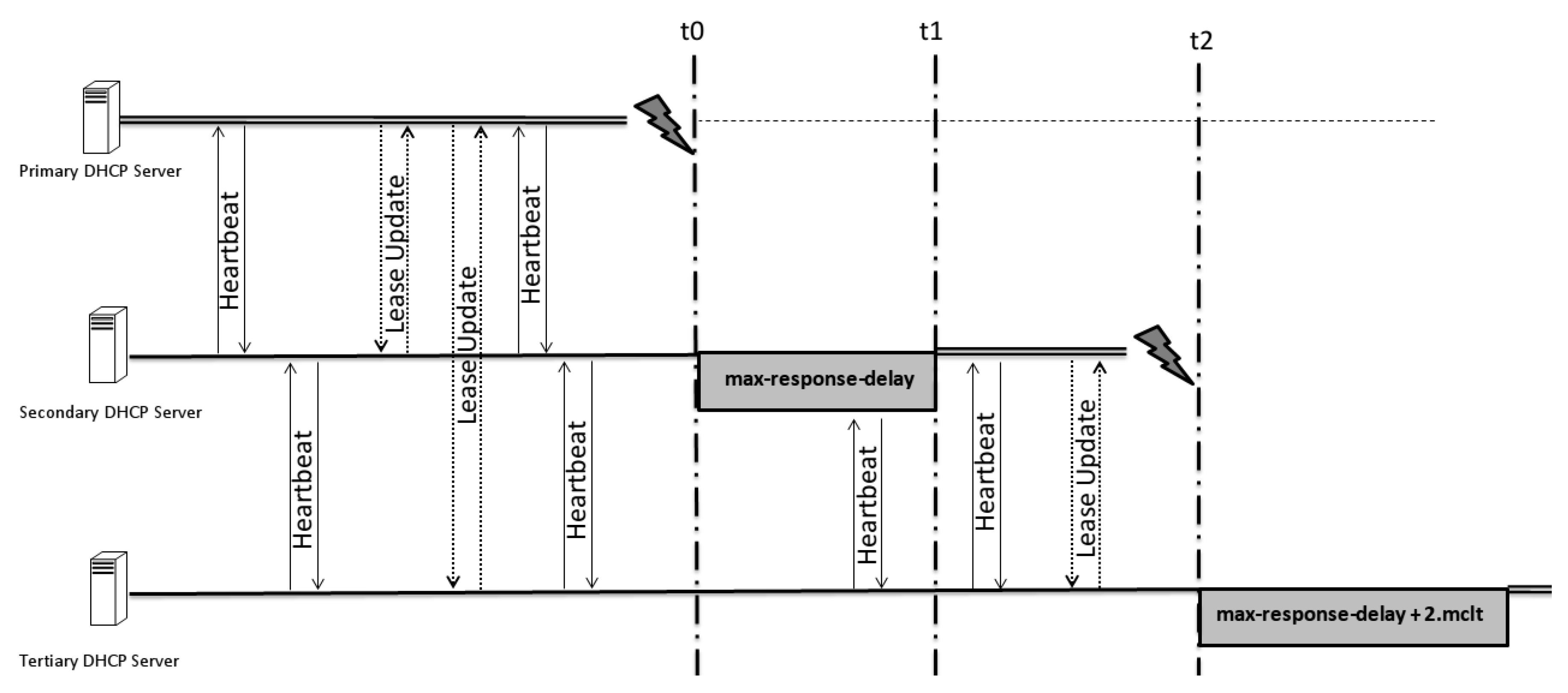
3.3. The Time Elapsing Problem
One of the problems related to extending the number of hierarchical servers is the time behavior between changes in the lead server. How can this time be defined if synchronization requires service interruptions? The solution is to specify a different expiration time for each hierarchical failover server. The time solution is based on the principle that the time check (max-response-delay) between two servers will be different in accordance with the number of hops in that scale. An agreement request is sent to a server, requesting that it become responsible, and it should agree not only with a primary server but also the servers that are secondary, tertiary, and so on.
These parameters are responsible for controlling the time elapse:
Max-response-delay: the maximum time that a server can wait to assume its pair function (become responsible).
MCLT: the maximum amount of time that one server can extend a lease for a DHCP client beyond the time known by the partner server. The MCLT defines the temporary lease period given by a failover partner server, and it also determines the amount of time that a server in a failover relationship will wait for a partner in the down state before assuming control over the entire IP address range [
11].
Max-unacked-updates: number of unacknowledged updates that can be sent before a BNDACK should be received.
These parameters define the behavior of the failover solution. They should be combined while observing the network settings in order to optimize the solution.
When more than two servers are used, there are different links between them. This means that there are different bandwidths, latency, packet losses, and redundancy links between them, and these bundles should be evaluated to set values for those parameters.
As shown in
Figure 12,
Figure 13 and
Figure 14, the difference between the time of one and that of another is what decides which particular server assumes responsibility for delivering IP addresses.
When there are no connections between consecutive servers—in other words, in each pair of servers, there will be at least one server down and the heartbeats of all servers that are up should not be answered—the importance of the chosen parameters is measured. The parameters that all servers have to guide themselves by in this scenario are the max-response-delay and the last BNDUPD packet sent. These packets inform the position of the responsive server and the number of hops between them. With this information, each server must be able to start to deliver IP addresses if it is allowed to switch itself to responsive without compromising the hierarchical order.
4. Simulations and Results
The schematic model of the hierarchical solution shows that this project version, defined by the issue of plural redundancy, naturally has a slightly heavier part of the already consolidated implementations in this process with only two servers.
In the proposed system, the use state is no longer the only variable that defines the state of each server as responsive. Relative to the previous model, this implies a longer scan layer, which, in turn, increases the level of complexity related to the mechanism of the presented solution.
According to Lin, Su, and Wang [
11,
12], companies do not necessarily adopt the draft of the Internet Engineering Task Force (IETF) failover protocol for the use of this technology in their components. As described in their article, Alcatel–Lucent [
13], Cisco [
14], Incognito [
15,
16], and BT (British Telecom) treat the scheme related to the failover protocol differently. Only Cisco, which significantly contributed to the protocol development, implements it fully and without adjustments.
Also, according to the article, the implemented versions continue working only with the dual redundancy mechanism (i.e., based only on two servers).
The current application in standard Linux servers was provided by the Internet Systems Consortium (ISC). This application was developed to implement all failover functionalities described in the DHCP handbook [
17].
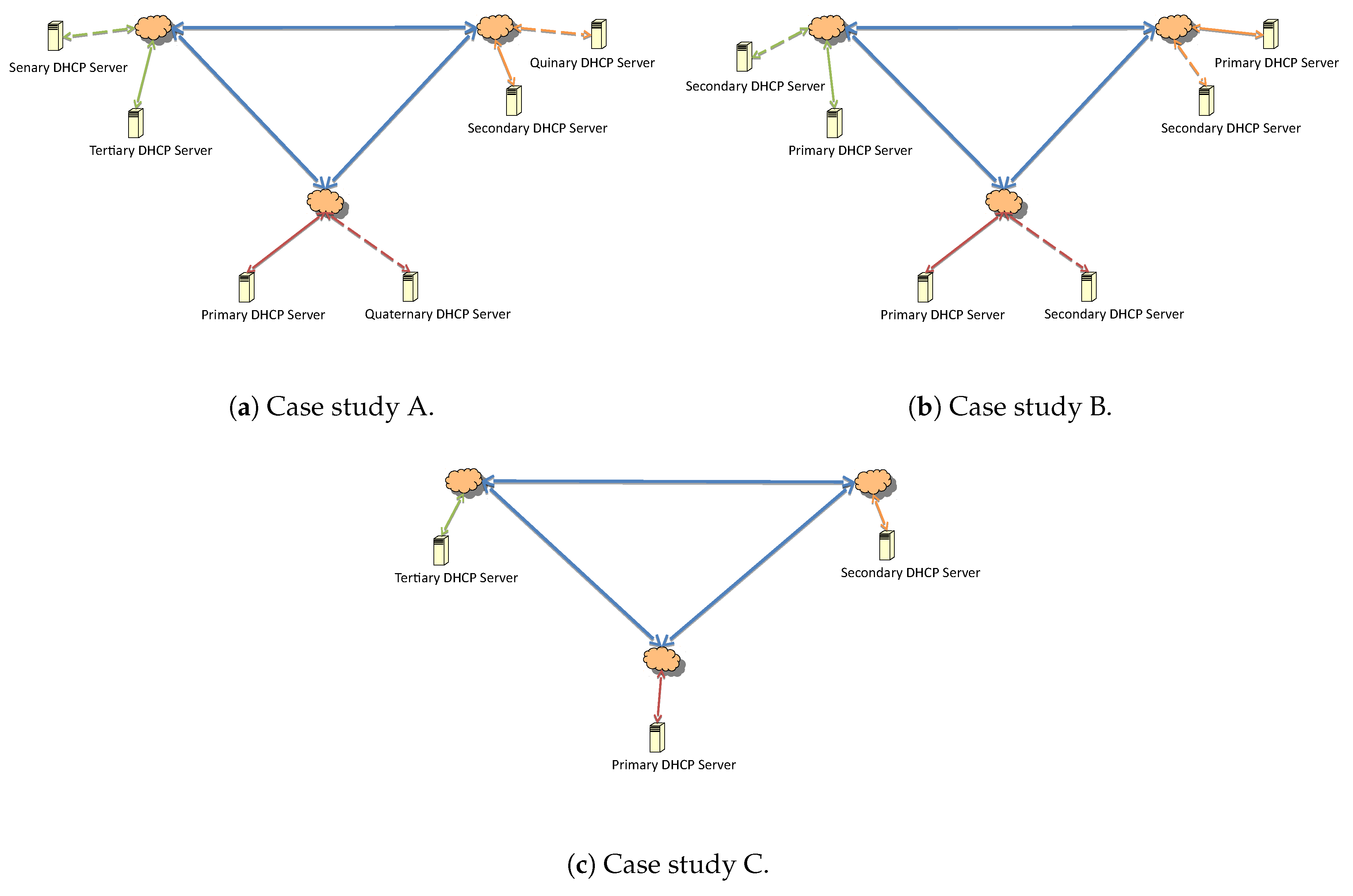
With respect to the architecture and the upgrade process, the messages exchanged between the servers are compared for the different configurations in
Figure 15.
The representation is made for three subnets. The number of update answers are considered equal to the number of submission updates, i.e., the number of BNDUPD messages was equal to the number of BNDACK messages in every update.
Given a configuration with n number of subnets, A and B were identical and represent twice the value of C. On the other hand, there was an increase in packet traffic in the network that connected the subnetworks. The requests that were broadcast inevitably reached all servers that were present in the process, since the relayed server agents did not monitor which one was responsive. That is, all broadcast requests (DHCPDISCOVER or DHCPREQUEST) that were sent by a host of a subnet behaved differently in cases A, B, and C.
Since n is the number of system subnets, it is inferred that:
In case A, the network flow generated will have a number of packets equal to two () sent if the communication is by broadcast.
In case B, as DHCP servers serve the internal network, there is no flow of packets within the network if the communication is inside the subnet only.
For C, the number of packages will be packets sent if the communication is by broadcast.
Expanding the Number of Subnets
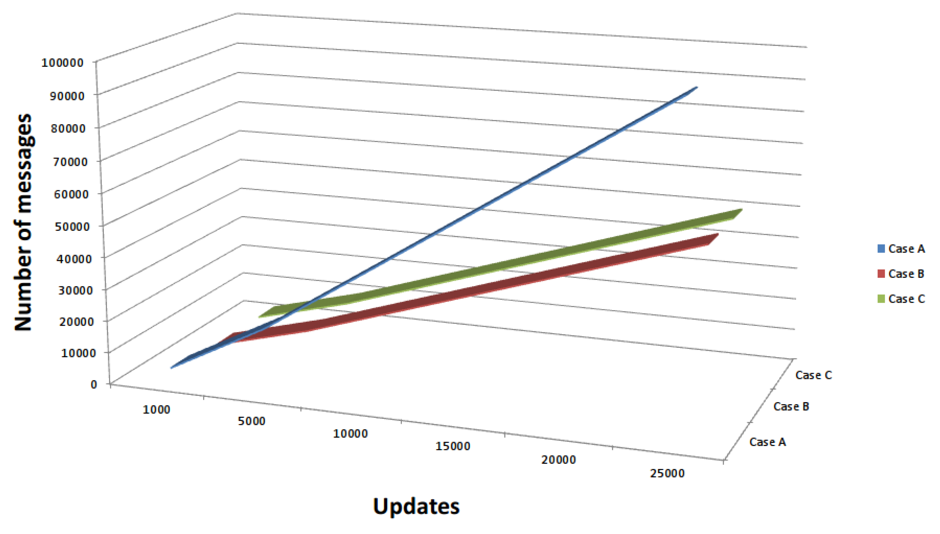
Figure 16 presents an increase in update messages between failover peers for case studies A, B, and C. As expected, the proposed solution can lead to an increase in the number of DHCP messages for a consistent IP address view over multiple interconnected subnets. These case studies were based on a three-subnet network, but if the model is generic, it is possible to extend the results and scenarios to apply to more than three subnets. In
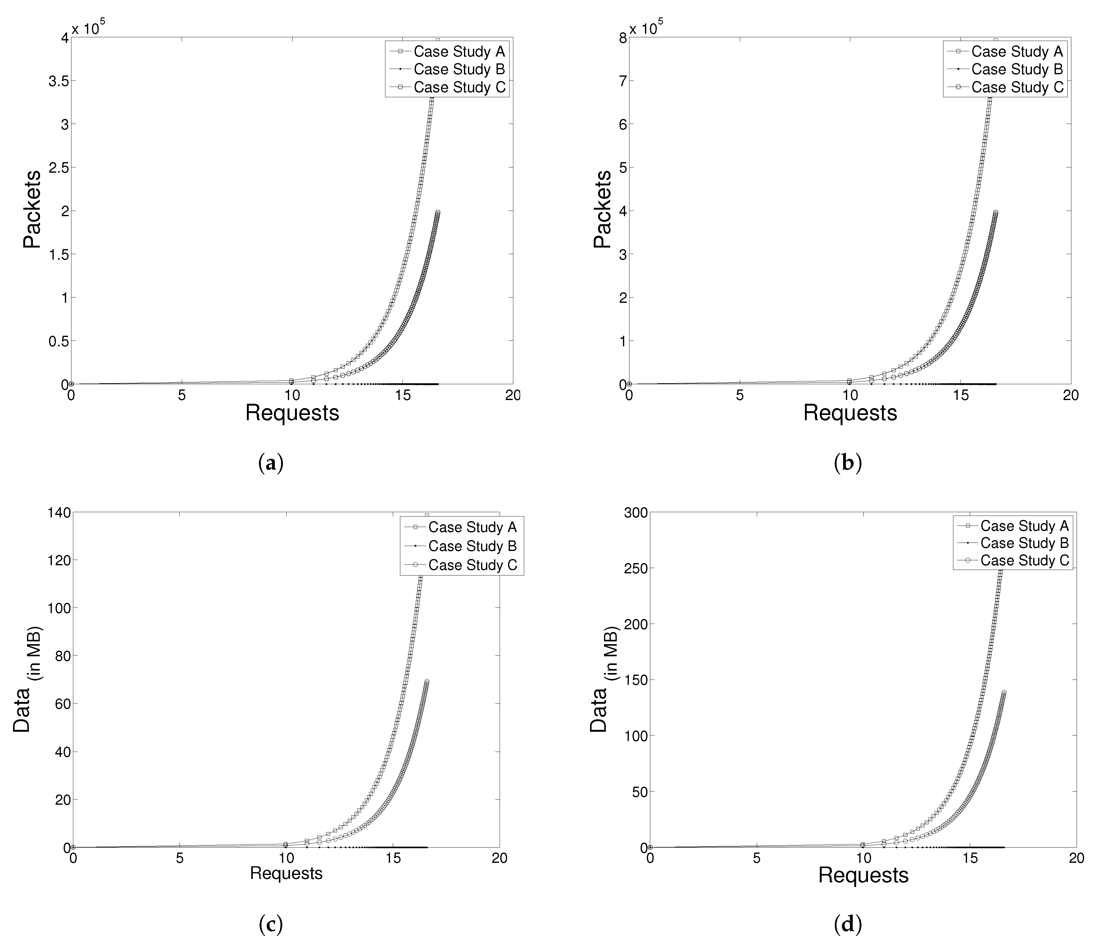
Figure 17a, there is a graph showing the number of packets circulating in a network of three subnets, given the number of requests from clients.
Since the size of each broadcast DHCP service related to the average package is 350 bytes long, the cost of network traffic could be estimated by the number of requests made and the number of subnets in the system for each case, as represented in
Figure 17c.
Figure 17b,d have the same representations, except in the last two figures, where the number of subnets is equal to five (
).
Figure 17b shows an increase in the number of packets circulating in a network when compared with
Figure 17a; consequently,
Figure 17d has a higher value of data traffic than
Figure 17c.


